EP0288992A2 - Connecteur de contact électrique - Google Patents
Connecteur de contact électrique Download PDFInfo
- Publication number
- EP0288992A2 EP0288992A2 EP88106735A EP88106735A EP0288992A2 EP 0288992 A2 EP0288992 A2 EP 0288992A2 EP 88106735 A EP88106735 A EP 88106735A EP 88106735 A EP88106735 A EP 88106735A EP 0288992 A2 EP0288992 A2 EP 0288992A2
- Authority
- EP
- European Patent Office
- Prior art keywords
- connector
- frame
- support
- contact elements
- guide plate
- Prior art date
- Legal status (The legal status is an assumption and is not a legal conclusion. Google has not performed a legal analysis and makes no representation as to the accuracy of the status listed.)
- Withdrawn
Links
Images
Classifications
-
- H—ELECTRICITY
- H01—ELECTRIC ELEMENTS
- H01R—ELECTRICALLY-CONDUCTIVE CONNECTIONS; STRUCTURAL ASSOCIATIONS OF A PLURALITY OF MUTUALLY-INSULATED ELECTRICAL CONNECTING ELEMENTS; COUPLING DEVICES; CURRENT COLLECTORS
- H01R13/00—Details of coupling devices of the kinds covered by groups H01R12/70 or H01R24/00 - H01R33/00
- H01R13/46—Bases; Cases
- H01R13/52—Dustproof, splashproof, drip-proof, waterproof, or flameproof cases
- H01R13/521—Sealing between contact members and housing, e.g. sealing insert
Definitions
- the invention relates to an electrical plug-in connector with an elongated metallic connector frame, which can be fixed to a device housing or the like and is formed from a frame front part and a frame rear part, a two-part insulating body enclosed between the two frame parts with a multiplicity of bores for receiving a multiplicity of them Insulating body mounted contact elements in the form of plug pins, sockets or the like., Which are connected to the rear of the connector to electrical lines and on the front of the connector combined into a multiple connector, plugged into a connecting cable mating contact elements, the insulating body a front, the holes for the front ends of the contact elements having support and guide plate made of thermoplastic material and a rear plate with corresponding holes for the rear ends of the contact elements.
- Plug contact connectors of this type have found widespread use in practice under the name of D-sub connectors; their dimensions and polar patterns are e.g. B. standardized in DIN 41652 and MS 18274 and MS 18276. The degree of protection of such connectors corresponds at least to the classification IP 54 specified in DIN 40050.
- the known D-Sub connector with two-part insulating body not only the front but also the back plate is molded from thermoplastic material and designed so that contact elements for crimping technology in it can be fixed mechanically.
- the invention has for its object to further develop the electrical plug-in connector of the type mentioned that a relatively simple manufacturing measures a water and dust protected version, in which the contact elements with their respective front ends still have a balance allowing small tolerances mobility and in which the contact elements can also be inserted and fixed in the bores of the insulating material body even after the cables have been struck, without impairing the sealing effect.
- the plug-in connector according to the invention in which this object is achieved, is essentially characterized in that the rear plate is designed as a sealing plate made of rubber-elastic plastic and thus in relation to the surface facing it, the support abutting the outwardly bent flange of the frame front part. and the guide plate is dimensioned so that it supports itself with its edge area facing away from the support and guide plate after connecting the two frame parts to one another while ensuring a perfect seal on an inwardly drawn support edge of the frame rear part, and that ring grooves with support switches for receiving are inserted in the holes penetrating the sealing plate radially projecting annular shoulders of the contact elements, which serve to secure the position of the contact elements in the inserted state, are provided.
- annular groove extending concentrically to this bore is provided in the sealing plate at a distance from each bore receiving a contact element, into which a correspondingly dimensioned, axially projecting annular bead of the support and engages the guide plate.
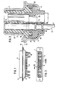
- the illustrated connector comprises an elongated connector frame 1 with a frame front part 2 and a frame rear part 3.
- Fig. 2 shows that the plug contact connector has the known D-sub connector configuration.
- a two-part insulating material body is clamped between the two frame parts 2, 3.
- This consists of a front support and guide plate 4, z. B. made of thermoplastic and a rear sealing plate 5 made of rubber-elastic plastic, for example an isomer or neoprene.
- Both plates 4, 5 of the insulating body are provided with a multiplicity of bores for receiving a corresponding multiplicity of contact elements in the form of plug pins (not shown), sockets 6 or coax contacts 7 or, similarly, concentrically constructed high-current contacts (not shown), which - as well the sockets 6 - are each provided with a large number of contact springs which ensure low contact resistance.
- the contact elements can be connected to a connecting cable in a known manner. This can be done by soldering, specifically in the area of a solder cup 8, in the area 9 using crimping technology or on the back of the coax contact elements via conventional coax connecting parts; 2 shows a usual spout 10 in this connection.
- Fig. 3 shows that the support and guide plate 4 in the vicinity of the two frame parts 2, 3 common parting plane 11 abuts an outwardly bent flange 12 of the front frame part 2.
- the rear plate designed as a sealing plate 5 is dimensioned in relation to the surface of the frame front part 2 facing it in such a way that with its edge region 13 facing away from the support and guide plate 4 after connection of both frame parts 2, 3 in the region of their common parting plane 11 supports an inwardly drawn support edge 14 of the frame rear part 3.
- the sealing plate 5 is under a prestress, which ensures the perfect seal even over a long period of time.
- Fig. 3 shows that the contact elements 6 are provided with two radially projecting ring shoulders 15, 16. These are used to secure the position of the contact elements 6 in the associated bores of the sealing plate 5 by inserting them after they have been inserted into the holes on support shoulders 17, 18, which are formed by annular grooves in the holes, come to rest.
- the bores in the sealing plate 5 are provided in the region of their mouths facing the corresponding bores in the front-side support and guide plate 4 with a bore constriction 19, 20 formed by a reduction in diameter.
- these bore areas of the sealing plate 5 are widened by radial displacement and lead to a tight embracing of the contact elements.
- annular groove 22 is provided at a distance from each hole in the sealing plate 5 and extends concentrically to this hole.
- a correspondingly dimensioned, axially projecting annular bead 23 of the support and guide plate 4 engages in this annular groove 22.
- the practically unyielding thermoplastic material of the support and guide plate 4 provides support for the rubber-elastic material around the bore area on the mouth side.
- the axially parallel section of the support and guide plate is of course not required since the pins extend freely in the direction of the plane determined by the upper edge of the frame front part.
- the upper boundary plane of the support and guide plate ends approximately in the area of the common parting plane 11 of the two frame parts 2, 3.
Landscapes
- Connector Housings Or Holding Contact Members (AREA)
Applications Claiming Priority (2)
| Application Number | Priority Date | Filing Date | Title |
|---|---|---|---|
| DE19873714552 DE3714552A1 (de) | 1987-04-30 | 1987-04-30 | Elektrischer steckkontaktverbinder |
| DE3714552 | 1987-04-30 |
Publications (2)
| Publication Number | Publication Date |
|---|---|
| EP0288992A2 true EP0288992A2 (fr) | 1988-11-02 |
| EP0288992A3 EP0288992A3 (fr) | 1990-05-16 |
Family
ID=6326641
Family Applications (1)
| Application Number | Title | Priority Date | Filing Date |
|---|---|---|---|
| EP88106735A Withdrawn EP0288992A3 (fr) | 1987-04-30 | 1988-04-27 | Connecteur de contact électrique |
Country Status (5)
| Country | Link |
|---|---|
| US (1) | US4812136A (fr) |
| EP (1) | EP0288992A3 (fr) |
| JP (1) | JPS6427169A (fr) |
| DE (1) | DE3714552A1 (fr) |
| NO (1) | NO881885L (fr) |
Cited By (2)
| Publication number | Priority date | Publication date | Assignee | Title |
|---|---|---|---|---|
| US5160280A (en) * | 1991-11-13 | 1992-11-03 | Chuang Tung Hsien | Electronic plug |
| US5509821A (en) * | 1994-11-14 | 1996-04-23 | Itt Corporation | D-sub connector |
Families Citing this family (13)
| Publication number | Priority date | Publication date | Assignee | Title |
|---|---|---|---|---|
| US4871328A (en) * | 1988-09-14 | 1989-10-03 | Simmonds Precision Products, Inc. | Hermetically sealing connector and method of use thereof |
| DE4017674C2 (de) * | 1990-06-01 | 2001-09-13 | Teves Gmbh Alfred | Elektrischer Schalter |
| JP2910390B2 (ja) * | 1992-03-31 | 1999-06-23 | 日本電気株式会社 | コネクタ |
| DE4309155C2 (de) * | 1993-03-22 | 1995-06-01 | Itt Cannon Gmbh | Steckverbinder, insbesondere für ein Mobiltelefon |
| JPH0765890A (ja) * | 1993-08-26 | 1995-03-10 | Sumitomo Wiring Syst Ltd | コネクタ |
| DE19836693A1 (de) | 1998-08-13 | 2000-02-17 | Continental Teves Ag & Co Ohg | Steckverbindung zum Anschluß von Signal- und Stromversorgungsleitungen an einen Verbraucher |
| DE10001735B4 (de) * | 2000-01-17 | 2006-07-06 | Pilz Gmbh & Co. Kg | Schutzvorrichtung gegen unerwünschte Inbetriebnahme einer Maschinenanlage |
| CA2454438A1 (fr) * | 2003-02-07 | 2004-08-07 | Hypertronics Corporation | Connecteur |
| USD596127S1 (en) | 2003-11-21 | 2009-07-14 | Hypertronics Corporation | Electrical connector |
| JP4839985B2 (ja) * | 2006-06-30 | 2011-12-21 | ミツミ電機株式会社 | プラグコネクタ |
| CN103326176A (zh) * | 2013-07-08 | 2013-09-25 | 苏州华旃航天电器有限公司 | 一种防水密封电连接器 |
| USD787448S1 (en) | 2014-08-18 | 2017-05-23 | Interlemo Holding S.A. | Electrical connector |
| USD863221S1 (en) | 2015-09-04 | 2019-10-15 | Interlemo Holding Sa | Illuminable female connector |
Family Cites Families (11)
| Publication number | Priority date | Publication date | Assignee | Title |
|---|---|---|---|---|
| GB725021A (en) * | 1952-05-07 | 1955-03-02 | Titeflex Inc | Shielded waterproof electrical plug and socket connectors |
| GB770307A (en) * | 1955-04-29 | 1957-03-20 | Rolls Royce | Improvements relating to electrical plug and socket connector devices |
| US2881406A (en) * | 1955-06-20 | 1959-04-07 | Cannon Electric Co | Moisture seal for connectors |
| US3101226A (en) * | 1961-05-05 | 1963-08-20 | Venture Products Inc | Knockdown metallic receptacles |
| US3292134A (en) * | 1964-03-31 | 1966-12-13 | Hughes Aircraft Co | Connector back seal |
| US3327282A (en) * | 1964-06-15 | 1967-06-20 | Amphenol Corp | Electrical connectors |
| US3631375A (en) * | 1970-04-01 | 1971-12-28 | Electronic Co Ltd Ab | Electrical connectors |
| US3816641A (en) * | 1973-05-14 | 1974-06-11 | Viking Industries | Underwater connector and method of making same |
| US4355855A (en) * | 1979-02-07 | 1982-10-26 | Dimitri Rebikoff | Deep water connector |
| JPS5937982Y2 (ja) * | 1981-09-05 | 1984-10-22 | 日本航空電子工業株式会社 | ソケツトコネクタ |
| EP0114479A3 (fr) * | 1982-12-27 | 1986-02-05 | AMP INCORPORATED (a New Jersey corporation) | Connecteur étanche à l'environnement et méthode et moyens pour sa fabrication |
-
1987
- 1987-04-30 DE DE19873714552 patent/DE3714552A1/de not_active Withdrawn
-
1988
- 1988-04-22 US US07/184,890 patent/US4812136A/en not_active Expired - Fee Related
- 1988-04-27 EP EP88106735A patent/EP0288992A3/fr not_active Withdrawn
- 1988-04-28 JP JP63104465A patent/JPS6427169A/ja active Granted
- 1988-04-29 NO NO881885A patent/NO881885L/no unknown
Cited By (2)
| Publication number | Priority date | Publication date | Assignee | Title |
|---|---|---|---|---|
| US5160280A (en) * | 1991-11-13 | 1992-11-03 | Chuang Tung Hsien | Electronic plug |
| US5509821A (en) * | 1994-11-14 | 1996-04-23 | Itt Corporation | D-sub connector |
Also Published As
| Publication number | Publication date |
|---|---|
| EP0288992A3 (fr) | 1990-05-16 |
| JPS6427169A (en) | 1989-01-30 |
| US4812136A (en) | 1989-03-14 |
| DE3714552A1 (de) | 1988-11-10 |
| NO881885D0 (no) | 1988-04-29 |
| JPH0457075B2 (fr) | 1992-09-10 |
| NO881885L (no) | 1988-10-31 |
Similar Documents
| Publication | Publication Date | Title |
|---|---|---|
| DE3688901T2 (de) | Steckverbinder für Leiterplatten, Leiterplattenaufbau unter Verwendung dieses Steckverbinders und Verfahren zur Herstellung dieses Leiterplattenaufbaus. | |
| DE69300865T3 (de) | Elektrischer verbinder mit blech als steckkontaktmaterial. | |
| EP0288992A2 (fr) | Connecteur de contact électrique | |
| EP0446572A1 (fr) | Bloc de connexion pour technique des télécommunications et de l'informatique | |
| DE2409075A1 (de) | Elektrischer verbinder | |
| DE3306263C2 (fr) | ||
| DE69807411T2 (de) | Kathodenstrahlröhrensockel | |
| DE2901885A1 (de) | Fuss fuer eine elektronenroehre | |
| EP0182070B1 (fr) | Bloc de connecteur électrique | |
| DE102006016793A1 (de) | Adaptervorrichtung mit elastischer Leitereinrichtung | |
| DE3717806A1 (de) | Verbindungsklemme | |
| DE2348992A1 (de) | Elektrischer verbinder | |
| DE29804836U1 (de) | Steckverbinder für ein geschirmtes Kabel | |
| DE2750540C2 (fr) | ||
| EP0567850B1 (fr) | Connexion d'un haut-parleur et d'un circuit imprimé situés tous deux dans un poste téléphonique | |
| EP0180000B1 (fr) | Dispositif à coupure comportant une pluralité de bornes à connexion sans dénudage de conducteurs électriques | |
| DE3629551C2 (fr) | ||
| EP0834966B1 (fr) | Connecteur enfichable pour plaquette à circuits située au-dessous d'un couvercle | |
| EP0284855A1 (fr) | Dispositif de contact et procédé de connexion d'un ruban conducteur | |
| DE19506713C2 (de) | Mehrpoliger Steckverbinder | |
| DE19803075A1 (de) | Trägerkörper für eine elektrische Kontaktanordnung | |
| DE4008386C2 (fr) | ||
| DE4023282C2 (de) | Regelmäßig nebeneinander oder senkrecht übereinander in einem Gehäuse angeordnete Buchsen zur Leiterplattenmontage | |
| EP0110084A1 (fr) | Elément de distribution électrique | |
| EP0234367B1 (fr) | Contact élastique pour bloc de connexion électrique |
Legal Events
| Date | Code | Title | Description |
|---|---|---|---|
| PUAI | Public reference made under article 153(3) epc to a published international application that has entered the european phase |
Free format text: ORIGINAL CODE: 0009012 |
|
| AK | Designated contracting states |
Kind code of ref document: A2 Designated state(s): AT BE CH DE ES FR GB IT LI LU NL SE |
|
| PUAL | Search report despatched |
Free format text: ORIGINAL CODE: 0009013 |
|
| AK | Designated contracting states |
Kind code of ref document: A3 Designated state(s): AT BE CH DE ES FR GB IT LI LU NL SE |
|
| 17P | Request for examination filed |
Effective date: 19900622 |
|
| 17Q | First examination report despatched |
Effective date: 19920807 |
|
| STAA | Information on the status of an ep patent application or granted ep patent |
Free format text: STATUS: THE APPLICATION HAS BEEN WITHDRAWN |
|
| 18W | Application withdrawn |
Withdrawal date: 19921207 |