EP0289032B1 - Dispositif d'alimentation pour magnétron et méthode de commande - Google Patents
Dispositif d'alimentation pour magnétron et méthode de commande Download PDFInfo
- Publication number
- EP0289032B1 EP0289032B1 EP88106860A EP88106860A EP0289032B1 EP 0289032 B1 EP0289032 B1 EP 0289032B1 EP 88106860 A EP88106860 A EP 88106860A EP 88106860 A EP88106860 A EP 88106860A EP 0289032 B1 EP0289032 B1 EP 0289032B1
- Authority
- EP
- European Patent Office
- Prior art keywords
- output voltage
- input current
- reference signal
- information
- current
- Prior art date
- Legal status (The legal status is an assumption and is not a legal conclusion. Google has not performed a legal analysis and makes no representation as to the accuracy of the status listed.)
- Expired - Lifetime
Links
Images







Classifications
-
- H—ELECTRICITY
- H05—ELECTRIC TECHNIQUES NOT OTHERWISE PROVIDED FOR
- H05B—ELECTRIC HEATING; ELECTRIC LIGHT SOURCES NOT OTHERWISE PROVIDED FOR; CIRCUIT ARRANGEMENTS FOR ELECTRIC LIGHT SOURCES, IN GENERAL
- H05B6/00—Heating by electric, magnetic or electromagnetic fields
- H05B6/64—Heating using microwaves
- H05B6/70—Feed lines
-
- H—ELECTRICITY
- H05—ELECTRIC TECHNIQUES NOT OTHERWISE PROVIDED FOR
- H05B—ELECTRIC HEATING; ELECTRIC LIGHT SOURCES NOT OTHERWISE PROVIDED FOR; CIRCUIT ARRANGEMENTS FOR ELECTRIC LIGHT SOURCES, IN GENERAL
- H05B6/00—Heating by electric, magnetic or electromagnetic fields
- H05B6/64—Heating using microwaves
- H05B6/66—Circuits
- H05B6/666—Safety circuits
-
- H—ELECTRICITY
- H02—GENERATION; CONVERSION OR DISTRIBUTION OF ELECTRIC POWER
- H02M—APPARATUS FOR CONVERSION BETWEEN AC AND AC, BETWEEN AC AND DC, OR BETWEEN DC AND DC, AND FOR USE WITH MAINS OR SIMILAR POWER SUPPLY SYSTEMS; CONVERSION OF DC OR AC INPUT POWER INTO SURGE OUTPUT POWER; CONTROL OR REGULATION THEREOF
- H02M3/00—Conversion of DC power input into DC power output
- H02M3/22—Conversion of DC power input into DC power output with intermediate conversion into AC
- H02M3/24—Conversion of DC power input into DC power output with intermediate conversion into AC by static converters
- H02M3/28—Conversion of DC power input into DC power output with intermediate conversion into AC by static converters using discharge tubes with control electrode or semiconductor devices with control electrode to produce the intermediate AC
- H02M3/325—Conversion of DC power input into DC power output with intermediate conversion into AC by static converters using discharge tubes with control electrode or semiconductor devices with control electrode to produce the intermediate AC using devices of a triode or a transistor type requiring continuous application of a control signal
- H02M3/335—Conversion of DC power input into DC power output with intermediate conversion into AC by static converters using discharge tubes with control electrode or semiconductor devices with control electrode to produce the intermediate AC using devices of a triode or a transistor type requiring continuous application of a control signal using semiconductor devices only
- H02M3/33507—Conversion of DC power input into DC power output with intermediate conversion into AC by static converters using discharge tubes with control electrode or semiconductor devices with control electrode to produce the intermediate AC using devices of a triode or a transistor type requiring continuous application of a control signal using semiconductor devices only with automatic control of the output voltage or current, e.g. flyback converters
- H02M3/33523—Conversion of DC power input into DC power output with intermediate conversion into AC by static converters using discharge tubes with control electrode or semiconductor devices with control electrode to produce the intermediate AC using devices of a triode or a transistor type requiring continuous application of a control signal using semiconductor devices only with automatic control of the output voltage or current, e.g. flyback converters with galvanic isolation between input and output of both the power stage and the feedback loop
-
- H—ELECTRICITY
- H02—GENERATION; CONVERSION OR DISTRIBUTION OF ELECTRIC POWER
- H02M—APPARATUS FOR CONVERSION BETWEEN AC AND AC, BETWEEN AC AND DC, OR BETWEEN DC AND DC, AND FOR USE WITH MAINS OR SIMILAR POWER SUPPLY SYSTEMS; CONVERSION OF DC OR AC INPUT POWER INTO SURGE OUTPUT POWER; CONTROL OR REGULATION THEREOF
- H02M7/00—Conversion of AC power input into DC power output; Conversion of DC power input into AC power output
- H02M7/42—Conversion of DC power input into AC power output without possibility of reversal
- H02M7/44—Conversion of DC power input into AC power output without possibility of reversal by static converters
- H02M7/48—Conversion of DC power input into AC power output without possibility of reversal by static converters using discharge tubes with control electrode or semiconductor devices with control electrode
- H02M7/53—Conversion of DC power input into AC power output without possibility of reversal by static converters using discharge tubes with control electrode or semiconductor devices with control electrode using devices of a triode or transistor type requiring continuous application of a control signal
- H02M7/537—Conversion of DC power input into AC power output without possibility of reversal by static converters using discharge tubes with control electrode or semiconductor devices with control electrode using devices of a triode or transistor type requiring continuous application of a control signal using semiconductor devices only, e.g. single switched pulse inverters
-
- H—ELECTRICITY
- H03—ELECTRONIC CIRCUITRY
- H03B—GENERATION OF OSCILLATIONS, DIRECTLY OR BY FREQUENCY-CHANGING, BY CIRCUITS EMPLOYING ACTIVE ELEMENTS WHICH OPERATE IN A NON-SWITCHING MANNER; GENERATION OF NOISE BY SUCH CIRCUITS
- H03B9/00—Generation of oscillations using transit-time effects
- H03B9/01—Generation of oscillations using transit-time effects using discharge tubes
- H03B9/10—Generation of oscillations using transit-time effects using discharge tubes using a magnetron
-
- H—ELECTRICITY
- H05—ELECTRIC TECHNIQUES NOT OTHERWISE PROVIDED FOR
- H05B—ELECTRIC HEATING; ELECTRIC LIGHT SOURCES NOT OTHERWISE PROVIDED FOR; CIRCUIT ARRANGEMENTS FOR ELECTRIC LIGHT SOURCES, IN GENERAL
- H05B6/00—Heating by electric, magnetic or electromagnetic fields
- H05B6/64—Heating using microwaves
- H05B6/66—Circuits
- H05B6/68—Circuits for monitoring or control
Definitions
- the invention relates to a magnetron feeding apparatus comprising a DC power supply, an inverter circuit for converting DC current into high-frequency power through the switching operation of a semiconductor switch, a high-tension transformer which converts the high-frequency power into high-tension power to be applied from a high-tension winding to a magnetron, whereas the filament of the magnetron is heated by a low-tension heating winding of the high-tension transformer, an output voltage detector for detecting the output voltage of the high-tension winding of the high-tension transformer, a current detector for detecting the input current into the inverter circuit, and a power controlling means having an error amplifier means for deriving a control value from the output voltage information signal of the output voltage detector and the current information signal of the current detector for controlling the switching operation of the semiconductor switch.
- the invention also relates to a method of controlling a magnetron feeding apparatus using a software processing portion.
- a magnetron feeding apparatus shown in Fig. 1 is adapted to convert DC power 2 from a power supply portion 1 into high-frequency power 5 by an inverter circuit 4 using a semiconductor switch 3 such as a transistor, and furthermore to convert it into high-tension power 7 by a high-tension transformer 6 to feed the power to a magnetron 8.
- a method of controlling the feeding power comprises steps of detecting the input current from a commercial power supply 9 by an input detecting portion 10, forming the difference information 12 between its value and the reference signal 11 by an error amplification circuit 13, a driving circuit 14 generates the driving pulse 15 corresponding to the difference information 12 to turn on, off the semiconductor switch 3, so that the input current is controlled to become a given value.
- the power feeding operation will be approximately one-seventh of feed power at the steady-state time when the magnetron 8 is oscillating.
- the input current is controlled to the given value in a period before the magnetron 8 starts its oscillation, the excessive power is applied on the heater 8 H and also the excessive voltage is applied upon between the anode 8 A and the cathode 8 K , thus resulting in the life service of the magnetron 8 being shorter because of discharging, deteriorated insulation or the like.
- the reference signal 11 is set to a value smaller at the steady-state time before the magnetron 8 starts its oscillation so as to be controlled to small input current which is proper to the heater heating operation.
- the reference signal 11 is switched to the value at the steady-state time after the lapse of the time sufficient enough for the magnetron 8 to start its oscillation, so that the input current may be controlled to a value at the steady-state time.
- the time for the timer 16 is set as five seconds for safety.
- the magnetron 8 does not produce a wave output for five seconds, so that three seconds of time are lost when the magnetron was warm. In case the magnetron 8 was cold only one second is wasted. Accordingly, the heating operation of such an electronic range is delayed.
- a magnetron feeding apparatus comprising an inverter circuit and a high-tension transformer for converting high-frequency power into high-tension power to be applied to a magnetron.
- the apparatus includes an output voltage detector, a current detector and a power controlling means for controlling the switching operation of a semiconductor switch of the inverter circuit.
- the current detector is provided to detect the peak current in the transistor of the inverter for the purpose of limiting it to a safe value.
- a filament control circuit Before the magnetron starts its oscillation, a filament control circuit provides a lower output voltage of the inverter circuit in order not to overload the filament of the magnetron and to avoid excessive high voltages.
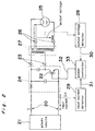
- FIG. 2 of the drawings A similar magnetron feeding apparatus without such a filament control circuit is shown in figure 2 of the drawings , which includes a power supply portion 21 for feeding DC current 20, an inverter circuit 24 which switches in high frequency the DC power supply 20 by a semiconductor switch 22 to convert it into high-frequency power 23, a high-tension transformer 27 which converts the high-frequency power 23 into the high-tension power 26 necessary for the operation of a magnetron 25, an output voltage detecting portion 28 which detects the output voltage V OUT of the high-tension transformer 27, an input current detecting portion 29 which detects the input current I IN into the inverter circuit 24, a power control portion 33 for controlling the switching operation of an inverter circuit 24 through the outputting of driving pulses 32 which turn on, off the semiconductor switch 22 by the use of the output voltage information 30 of the output voltage detecting portion 28 and the input current information 31 of the input current detecting portion 29.
- a magnetron feeding apparatus of the kind as described in the preamble of claim 1 is characterized in that the power controlling means is adapted such the switching operation of the semiconductor switch is controlled only by the larger control value derived from the output voltage information signal or an input current information signal; a comparator for comparing the voltage output information signal with a first reference signal and controlling a transistor into conductive state if the voltage output information signal is larger than the first reference signal; a second error amplifier for comparing the current input information signal with a second reference signal to provide an output signal for controlling the switching operation of the semiconductor switch; the output of the transistor being connected to the second reference signal for short-circuiting it in its conductive state; and a further comparator comparing the output voltage information signal with a further reference signal, the further comparator enabling gradual increasing means if the output voltage information is smaller than the further reference signal.
- an improved magnetron feeding apparatus removes the above-described wasteful time without lowering the service life of the magnetron.
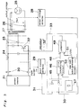
- Fig. 3 is a block diagram showing the first embodiment of a power control portion 33.
- a diode circuit 45 inputs the larger information of the output voltage information 30 and the input current information 31 into a first error amplification circuit 46.
- An error amplification circuit 46 outputs a difference signal 48 between this input and the output of a reference signal generating circuit 47.
- a comparator 49 outputs a driving pulse 32' which turns on, off the semiconductor switch 22 by the difference signal 48 and a saw-tooth wave 51 from a saw-tooth wave generating circuit 50 through a comparator 49.
- the output in the error amplification circuit 46 is reduced to decrease the on time of the driving pulse 32', so that the operation is effected in such a direction as to reduce the input current I IN .
- the on time of the driving pulse 32' is increased, so that the operation is effected in such a way as to increase the input current I IN .
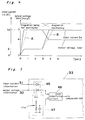
- Such time constant circuit 47a as shown in Fig. 5 is used for the reference signal generating circuit 47, with the output voltage V OUT may be gradually increased up to 7 KV as shown in the dotted line A of Fig. 4.
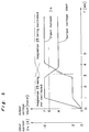
- an additional reference signal generating circuit 53 equivalent to, for example 6 KVo-p in the output voltage V OUT is 6 KVo-p or more, and it is turned on when the output voltage V OUT is 6 KVo-p or lower, so that the input current I IN may be gradually increased in the output voltage V OUT ⁇ 6 KVo-p as shown in Fig. 8.
- Fig. 9 is a block diagram showing a second embodiment of a power control portion.
- a first error amplification circuit 55 outputs a difference signal 57 between the output voltage information 30 and the reference signal of a reference signal generating circuit 56 to a diode circuit 58.
- a second error amplification circuit 59 outputs a difference signal 61 between the input current information 31 and the reference signal of a reference signal generating circuit 60 to the diode circuit 58.
- the diode 58 outputs to a comparator 62 the smaller one of two difference signals 57, 61.
- the comparator 62 outputs a driving pulse 32'' which turns on, off the semiconductor switch 22 by the input and the sawtooth wave 64 from a sawtooth wave generating circuit 63.
- the required input current I IN when the output voltage V OUT is 7 KVo-p as shown in Fig. 4 or 8 is approximately 2 A , so that the difference signal 61 from the second error amplification circuit 59 becomes larger than the difference signal 57 from the first error amplification circuit 55.
- the required input current I IN less i.e., the difference signal 57 from the first error amplification circuit 55 is selectively outputted by the diode circuit 58.
- the output of the first error amplification circuit 55 is decreased to reduce the on time of the driving pulse 32'', so that the operation is effected in such a direction as to decrease the output voltage V OUT .
- the on time of the driving pulse 32'' increases so that the operation takes place in such a direction as to increase the output voltage V OUT .
- the output voltage V OUT when the input current I IN is approximately 4A as shown in Fig. 4 or 8, so that the difference signal 57 from the first error amplification circuit 55 becomes larger than the difference signal 61 from the second error amplification circuit 59.
- the required input current I IN small i.e., the difference signal from the second error amplification circuit 59 is selectively outputted by the diode circuit 58.
- the output of the second error amplification 59 decreases to reduce the on time of the driving pulse 32'', so that the operation is effected in such a direction as to reduce the input current I IN .
- the input current information 31 decreases, so that the operation is effected in such a way as to increase to make the input current I IN more through the increase of the on time of the driving pulse 32''.
- the starting characteristics becomes the same as those of the starting characteristics graph of the first embodiment shown in Fig. 4.
- the reference signal generating circuit 56 is constructed to have the time constant of the above-described Fig. 5, so that the controlling operation may be performed so as to gradually increase the output voltage V OUT as far as 7 KV as shown in the dotted line A of Fig. 4.
- the gradual increasing circuit 52 shown in Fig. 6 is inserted between the diode circuit 58 and the comparator 62, so that the controlling operation may be controlled so as to gradually increase the output voltage V OUT and the input current I IN as in the dotted line A of Fig. 4 and the dotted line thereof.
- the gradual increasing circuit 52 is turned on and off in accordance with the output voltage information 30 as shown in Fig. 7 to gradually increase the input current I IN .
- Fig. 10 is a block diagram showing the third embodiment of the power control portion 33.
- an error amplification circuit 65 outputs to a comparator 69 the difference signal 68 between the reference signal from a reference signal generating circuit 67 passing through a gradual increasing, gradual decreasing circuit 66, and the input current information 31.
- the comparator 69 outputs a driving pulse 32'' which switches on, off the semiconductor switch 22 through the difference signal 68 and a sawtooth wave 71 from a sawtooth wave generating circuit 70.
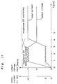
- the output voltage V OUT is approximately 4 KVo-p , with the switch 72s being off.
- the input current information 31 increases, the output of the fourth error amplification circuit 65 is decreased to reduce the on time of the driving pulse 32'' so that the operation is effected in such a direction as to reduce the input current I IN .
- the on time of the driving pulse 32'' is decreased so that an operation is effected in such a way as to increase the input current I IN .
- Fig. 11 is a characteristic graph of a magnetron feeding apparatus in such a condition as described hereinabove.
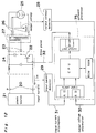
- Fig. 12 is a circuit block diagram in a case where the power control of the magnetron feeding apparatus is effected by software processing.
- a software processing portion 75 inputs the input current information 31 from the input current detecting portion 29 and the output voltage information 30 from the output voltage detecting portion 28 to change the on time of the driving pulse 32 which turns on, off the semiconductor switch 22 in accordance with the value of two information 31, 30 to perform the power control of the magnetron feeding apparatus.
- An A/D converter which is adapted to convert the input current information 31 and the output voltage information 30 into digital signals convenient for software processing, is used for the software processing portion 75, with the converting operation being omitted in the present application.
- Fig. 13 is a conceptional diagram of a program flow of the software processing portion 75.
- the power supply is turned on to perform the initial setting 76 for inner data or the like, thereafter to repeat the inputting operation 77 of the output voltage information 30 and the input current information 31, the production of the data for setting the on time to set the on time of the semiconductor switch by the use of this information the outputting operation 79 of the deriving pulse 32 for turning on, off the semiconductor switch 22 by the use of the data for setting the on time.
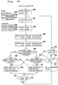
- Fig. 14 is a flow chart showing the first embodiment of the software processing portion 75.
- the RAM (on data) initial setting 80 is effected, to shorten the initial on time of the semiconductor switch 22, when the power supply is turned on.
- the timer (on) start 81 for setting the on time of the semiconductor switch 22 is effected in accordance with the value of the RAM (on data) 90, so that the output 82 of the driving pulse (on) which turns on the semiconductor switch 22 is effected.
- RAM (output voltage information) for inputting the output voltage information 30 ⁇ the output voltage information 83 and RAM (input current information for inputting the input current information 31 ⁇ the input current 84 are performed.
- the two information is compared in RAM (output voltage information) > RAM (input current information) 85.
- the larger information is compared with the given value (A) 88 in RAM (output voltage information) > given value (A) 86 or RAM (input current information) > given value (A) 87.
- the RAM (on data) 90 is decreased by the RAM (on data) - given value (B) 89.
- the RAM (on data) 90 is increased by the RAM (on data) + given value (C) 91. Then, when the timer (on) completion 92 and the driving pulse (off) output 93 are performed to release the on condition of the semiconductor switch 22.
- the output voltage information 30 is larger than the input current information 31 in a period before the magnetron 25 starts its oscillation.
- the RAM (output voltage information) 96 is larger than the given value (A) 88, the RAM (on data) 90 is decreased to make the on time of the semiconductor switch 22 shorter to reduce the output voltage V OUT .
- the RAM (on data) 90 is increased to make the output voltage V OUT more.
- the input current information 31 becomes larger than the output voltage information 30.
- the RAM (input current information) 87 is compared with the given value (A) 88 to increase or decrease the RAM (on data) 90 in accordance with the result so that an operation is effected so as to control the input current I IN .
- the large information of the output voltage information 30 and the input current information 31 is controlled to conform to the given value (A) 88. Also, the value size of the given value (B) 98 and the given value (C) 99 may vary the change speed of the increase, decrease of the output voltage V OUT , the input current I IN .
- Fig. 15 is a flow chart showing the second embodiment of the software processing portion 75.
- the initial setting 100 of the RAM (on data), RAM (on data V), RAM (on data I) is performed so as to shorten the initial on time of the semiconductor switch 22.
- the timer (on ) start 81 is effected to set the on time of the semiconductor switch 22 in accordance with the value of the RAM (on data) 90, so that the (on) output 82 of the driving pulse (on) which turns on the semiconductor switch 22 is effected.
- the RAM (output voltage information) for inputting the output voltage information 30 ⁇ the output voltage information 83 is effected.
- the information is compared in RAM (output voltage information) > given value (D) 101.
- the RAM (on data V) 104 is reduced in RAM (on data V) - given value (E) 103.
- the RAM (on data V) 104 is increased in RAM (on data V) + given value (F) 105.
- RAM (input current information) ⁇ input current information 84, RAM (input current information) > given value (G) 106, and RAM (on data I) - given value (H) 107 or RAM (on data I) + given value (l) 108 are effected.
- RAM (on data V) > RAM (on data I) 109 a comparing operation is performed in RAM (on data V) > RAM (on data I) 109.
- RAM (on data V) 104 is smaller, RAM (on data) ⁇ RAM (on data V) 110 is effected.
- RAM (on data I) 111 is smaller, RAM (on data) ⁇ RAM (on data I) 112 is effected.
- the off time of the semiconductor switch 22 is controlled by the timer (off) start 94 and the timer (off) completion 95 and thereafter it returns to the timer (on) start 81.
- the RAM (output voltage information) 96 approaches the given value (D) 102 in a period before the magnetron 25 starts its oscillation. Also, RAM (input current information) 97 ⁇ given value (G) 113, thus resulting in RAM (on data V) 104 ⁇ RAM (on data I) 111, with RAM (on data) 90 conforming in value to the RAM (on data V) 104.
- RAM (input current information) 97 is approached to the given value 113, RAM (output voltage information 96 ⁇ given value (D)) 102, thus resulting in RAM (on data V) 104 > RAM (on data I) 111, with RAM (on data) 90 conforming to the RAM (on data I) 111.
- the RAM (on data I) 111 is decreased when the RAM (input current information) 97 is larger than the given value (G) 113 to make the on time of the semiconductor switch 22 shorter so as to decrease the input current I IN .
- RAM (on data I) 111 is increased to increase the input current I IN , so that the input current information 31 is controlled to conform to the given value (G) 113.
- the processing that the value of the RAM (on data) 90 is set though the choice of the smaller of the RAM (on data V) 104 and the RAM (on data I) 111 results in the choice of the smaller one of the required input current I IN .
- the change speed of increase, decrease in the output voltage V OUT may be varied by the given value (E) and the given value (F) 115, while the change speed of increase, decrease in the input current I IN may be varied by the given value (H) 116 and the given value (I) 117.
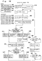
- Fig. 16 is a flow chart showing the third embodiment of a software processing portion 75.
- the initial setting 118 of the RAM (on data), RAM (current reference) is effected to shorten the first on time of the semiconductor switch 22.
- the timer (on) start 81 is effected which sets the on time of the semiconductor switch 22 by the use of the RAM (on data) 90 to perform the outputting operation 82 of the driving pulse (on) which turns on the semiconductor switch 22.
- the RAM (output voltage information) for inputting the output voltage information 30 ⁇ the output voltage information 83 is effected.
- RAM (output voltage information)> given value (J) 119 the RAM (current reference) 122 is decreased in RAM (current reference) - given value (K) 121.
- the RAM (current reference) 122 is increased in (RAM current reference) + given value (L) 123.
- the maximum value of the RAM (current reference) 122 in this case is restricted to the given value (M) limit 124 of the RAM (current reference) 122.
- RAM input current information
- This information is compared with the RAM (input current information) > RAM (current reference) 126.
- the RAM (on data) 90 is decreased in the RAM (on data) - given value (N) 127.
- the RAM (on data) 90 is increased in RAM (on data) + given value ( o ⁇ ) 128.
- the RAM (output voltage information) 96 approaches the given value (J) 120 in a period before the magnetron 25 oscillates, with the RAM (current reference) 122 being not limited to the given value (M) 125.
- the RAM (output voltage information) 96 When the RAM (output voltage information) 96 is larger than the given value (J) 120, the RAM (current reference) 122 is reduced, with the result that RAM (on data) 90 is reduced so that the RAM (input current information) 97 may follow the reduced RAM (current reference) 122. Accordingly, the on time of the semiconductor switch 22 is reduced to decrease the output voltage V OUT and the input current I IN . Inversely, when the RAM (output voltage information) 96 is smaller than the given value (J) 120, the RAM (on data) 90 is increased and the output voltage V OUT and the input current I IN are increased.
- the RAM (output voltage information) 96 is controlled to conform to the given value (J) 120 in this period.
- RAM output voltage information
- J given value
- RAM current reference
- the RAM (input current information) 97 is larger than the given value (M) 125
- the RAM (on data) 90 is reduced to shorten the on time of the semiconductor switch 22 to reduce the input current I IN .
- the RAM (on data) 90 is increased to make the input current Iin more, so that RAM (input current information) 97 is controlled to conform to the given value (M) 125.
- the change speed of the increase, decease of the output voltage V OUT may be respectively varied by the given value (K) 129, the given value (L) 130, the given value (lV) 131, and the given value ( o ⁇ ) 132. Also, the change speed of the increase, decrease of the input current I IN is respectively varied by the given value (N) 131 and the given value ( o ⁇ ) 132.
- optimum voltage, power may be steadily fed in a period before the magnetron starts its oscillation, the possible oscillation condition of the magnetron may be reached in a short time without application of the excessive voltage.
- the condition automatically moves to the controlling operation may be effected without consumption of the wasteful time- as far as the oscillating condition of the magnetron, and also, the oscillating condition may be steadily continued.
Landscapes
- Engineering & Computer Science (AREA)
- Power Engineering (AREA)
- Physics & Mathematics (AREA)
- Electromagnetism (AREA)
- Control Of High-Frequency Heating Circuits (AREA)
Claims (5)
- Appareil d'alimentation de magnétron comprenant une alimentation (21) électrique à courant continu, un circuit inverseur pour convertir un courant continu en une puissance à haute fréquence par l'intermédiaire d'une opération de commutation d'un commutateur (22) à semi-conducteur, et un transformateur (27) à haute tension qui convertit la puissance à haute fréquence en une puissance à haute tension destinée à être appliquée par un enroulement (26) à haute tension à un magnétron (25), tandis que le filament du magnétron (25) est chauffé par un enroulement chauffant à basse tension du transformateur (27) à haute tension ; un détecteur (28) de tension de sortie pour détecter la tension de sortie de l'enroulement (26) à haute tension du transformateur (27) à haute tension, un détecteur (29) de courant pour détecter le courant d'entrée fourni au circuit inverseur ; et
des moyens (33, 75) de commande de puissance ayant un amplificateur d'erreur pour déterminer une valeur de commande à partir du signal (30) d'information de tension de sortie du détecteur (28) de tension de sortie et du signal (31) d'information de courant du détecteur (29) de courant, pour commander l'opération de commutation du commutateur (22) à semi-conducteur ;
caractérisé par :le fait que les moyens (33) de commande de puissance sont conçus de façon que l'opération de commutation du commutateur (22) à semi-conducteur ne soit commandée que par la valeur de commande la plus grande déterminée à partir du signal (30) d'information de tension de sortie ou d'un signal (31) d'information de courant d'entrée ;un comparateur (72) pour comparer le signal (30) d'information de tension de sortie avec un premier signal (73) de référence et pour commander un transistor (72s) afin de le faire passer à l'état conducteur si le signal (30) d'information de tension de sortie est supérieur au premier signal (73) de référence ;un second amplificateur (65) d'erreur pour comparer le signal (31) d'information d'entrée de courant avec un second signal (67) de référence afin de fournir un signal (68) de sortie pour commander l'opération de commutation du commutateur (22) à semi-conducteur ;la sortie du transistor (72s) étant connectée au second signal (67) de référence pour le court-circuiter dans son état conducteur ; etun autre comparateur (54) comparant le signal (30) d'information de tension de sortie avec un autre signal (53) de référence, l'autre comparateur (54) activant des moyens (52a) d'accroissement progressif si l'information de tension de sortie est inférieure au signal (53) de référence supplémentaire. - Appareil selon la revendication 1,
caractérisé en ce que le détecteur (28) de tension de sortie et le détecteur (29) de courant d'entrée sont conçus pour fournir un signal (30) d'information de tension de sortie et un signal d'information de courant d'entrée d'amplitudes de signal comparables, et
en ce que ces deux signaux (30, 31) d'information sont fournis à un sélecteur (45) qui ne laisse passer que le plus grand des deux signaux d'information vers un amplificateur (46) d'erreur commun recevant un signal (47) de référence. - Appareil selon la revendication 1,
caractérisé par un premier amplificateur (55) d'erreur destiné à comparer le signal (30) d'information de sortie de tension avec un premier signal (56) de référence et pour fournir en sortie une première valeur (57) de commande ;un second amplificateur (59) d'erreur destiné à comparer le signal (31) d'information d'entrée de courant avec un second signal (60) de référence et à fournir en sortie une seconde valeur (61) de commande ; etun sélecteur (58) connecté aux deux amplificateurs (55, 59) d'erreur et ne laissant passer que la plus petite des deux valeurs (57, 61) de commande pour commander l'opération de commutation du commutateur (22) à semi-conducteur. - Appareil selon l'une quelconque des revendications précédentes,
caractérisé par des moyens (47a; 52a; 66C, 66R1) d'accroissement progressif pour commander l'accroissement du signal ou des signaux de référence (47, 67) ou de la valeur ou des valeurs de commande (52), afin de faire croître progressivement le signal de commande pour commander l'opération de commutation du commutateur (22) à semi-conducteur. - Procédé pour commander un appareil d'alimentation de magnétron comprenant une alimentation électrique à courant continu, un circuit inverseur pour convertir un courant continu en une puissance à haute fréquence au moyen de l'opération de commutation d'un commutateur à semi-conducteur, un transformateur à haute tension qui convertit la puissance à haute fréquence en une puissance à haute tension destinée à être appliquée par un enroulement à haute tension à un magnétron, tandis que le filament du magnétron est chauffé par un enroulement chauffant à basse tension du transformateur à haute tension, et l'utilisation d'une partie (75) de traitement par logiciel pour élaborer les impulsions d'attaque du commutateur à semi-conducteur sur la base d'un signal (30) d'information de tension de sortie et d'un signal (31) d'information de courant d'entrée ;
la partie (75) de traitement par logiciel ayant une séquence programmée comprenant les étapes qui consistent :a) à effectuer une initialisation de données internes après que l'alimentation électrique a été mise en oeuvre,b) à répéter l'opération de fourniture de l'information de tension d'entrée et de l'information de courant d'entrée,c) à effectuer une opération d'élaboration de données pour fixer le temps de fermeture du commutateur à semi-conducteur sur la base des deux signaux d'information fournis,d) à effectuer une opération de fourniture d'une impulsion d'attaque pour fixer la largeur d'impulsion de l'impulsion d'attaque qui ferme ou ouvre le commutateur à semi-conducteur ;caractérisé par les étapes qui consistent :e5) à fournir le signal (30) d'information de tension de sortie,f5) à comparer le signal (30) d'information de tension de sortie avec une première valeur (D) de référence pour réduire un signal de référence de courant lorsqu'il est supérieur à la première valeur (D) de référence et pour faire croître le signal de référence de courant lorsqu'il est inférieur à la première valeur (D) de référence, etg5) à limiter le plus grand des signaux de référence de courant augmenté, à une seconde valeur (E) de référence,h5) à fournir le signal (31) d'information de courant d'entrée,i5) à comparer le signal (31) d'information de courant d'entrée avec le signal de référence de courant pour réduire les données de fixation du temps de fermeture, lorsqu'il est supérieur au signal de référence de courant, et pour faire croître la donnée lorsqu'elle est inférieure au signal de référence de courant.
Applications Claiming Priority (6)
| Application Number | Priority Date | Filing Date | Title |
|---|---|---|---|
| JP106636/87 | 1987-04-30 | ||
| JP62106636A JP2537859B2 (ja) | 1987-04-30 | 1987-04-30 | 高周波加熱装置 |
| JP117344/87 | 1987-05-14 | ||
| JP11733987A JPH088143B2 (ja) | 1987-05-14 | 1987-05-14 | 高周波加熱装置 |
| JP117339/87 | 1987-05-14 | ||
| JP11734487A JPH088144B2 (ja) | 1987-05-14 | 1987-05-14 | 高周波加熱装置 |
Publications (3)
| Publication Number | Publication Date |
|---|---|
| EP0289032A2 EP0289032A2 (fr) | 1988-11-02 |
| EP0289032A3 EP0289032A3 (fr) | 1990-01-31 |
| EP0289032B1 true EP0289032B1 (fr) | 1997-01-08 |
Family
ID=27310789
Family Applications (1)
| Application Number | Title | Priority Date | Filing Date |
|---|---|---|---|
| EP88106860A Expired - Lifetime EP0289032B1 (fr) | 1987-04-30 | 1988-04-29 | Dispositif d'alimentation pour magnétron et méthode de commande |
Country Status (7)
| Country | Link |
|---|---|
| US (1) | US4900989A (fr) |
| EP (1) | EP0289032B1 (fr) |
| KR (1) | KR910001987B1 (fr) |
| AU (1) | AU592262B2 (fr) |
| BR (1) | BR8802124A (fr) |
| CA (1) | CA1302513C (fr) |
| DE (1) | DE3855740T2 (fr) |
Cited By (1)
| Publication number | Priority date | Publication date | Assignee | Title |
|---|---|---|---|---|
| US8017893B2 (en) * | 2004-04-28 | 2011-09-13 | Panasonic Corporation | High-frequency heating apparatus |
Families Citing this family (16)
| Publication number | Priority date | Publication date | Assignee | Title |
|---|---|---|---|---|
| JPH01246787A (ja) * | 1988-03-28 | 1989-10-02 | Toshiba Corp | 調理器 |
| FR2679075B1 (fr) * | 1991-07-09 | 1993-10-22 | Moulinex Sa | Dispositif de detection du dysfonctionnement d'une charge telle qu'un magnetron. |
| FR2680297B1 (fr) * | 1991-08-09 | 1996-10-25 | Moulinex Sa | Dispositif d'alimentation d'une charge non lineaire. |
| US5574338A (en) * | 1995-06-07 | 1996-11-12 | Nicollet Technologies Corporation | Control circuit for gas discharge lamps, which has a transformer with start and run windings |
| US5708356A (en) * | 1995-08-04 | 1998-01-13 | Kabushiki Kaisha Toshiba | Apparatus for supplying stabilized power to a load having voltage-current characteristics exhibiting partial negative resistance |
| WO1999007188A2 (fr) * | 1997-08-01 | 1999-02-11 | Koninklijke Philips Electronics N.V. | Dispositif de circuit |
| US6323603B1 (en) | 1998-02-18 | 2001-11-27 | Nicollet Technologies Corporation | Resonant flyback ignitor circuit for a gas discharge lamp control circuit |
| GB2335746B (en) | 1998-03-24 | 2000-10-11 | Samsung Electronics Co Ltd | Microwave oven with food quantity detection |
| KR100284546B1 (ko) * | 1998-04-30 | 2001-05-02 | 윤종용 | 전자렌지의 마그네트론 구동제어장치 및 방법 |
| KR100290150B1 (ko) * | 1998-07-29 | 2001-05-15 | 윤종용 | 전자렌지의 이상상태 검출장치 및 그 방법 |
| US6181082B1 (en) * | 1998-10-15 | 2001-01-30 | Electro-Mag International, Inc. | Ballast power control circuit |
| KR100341334B1 (ko) | 1999-12-09 | 2002-06-22 | 윤종용 | 직류용 전자렌지의 안전회로와 그 제어방법 |
| JP2002367768A (ja) * | 2001-06-04 | 2002-12-20 | Matsushita Electric Ind Co Ltd | マグネトロン駆動用電源 |
| EP1483941B1 (fr) * | 2002-03-12 | 2008-03-19 | Matsushita Electric Industrial Co., Ltd. | Transformateur survolte a entrainement magnetron |
| EP1614326B1 (fr) * | 2003-04-11 | 2009-07-29 | Panasonic Corporation | Appareil de chauffage a hautes frequences |
| JP4871522B2 (ja) * | 2005-04-04 | 2012-02-08 | パナソニック株式会社 | 高周波誘電加熱用電力制御方法及びその装置 |
Family Cites Families (7)
| Publication number | Priority date | Publication date | Assignee | Title |
|---|---|---|---|---|
| US4005370A (en) * | 1974-09-10 | 1977-01-25 | Matsushita Electric Industrial Co., Ltd. | Power supply means for magnetron |
| GB1542662A (en) * | 1975-09-12 | 1979-03-21 | Matsushita Electric Industrial Co Ltd | Power supply |
| US4318165A (en) * | 1980-04-21 | 1982-03-02 | General Electric Company | Resonant-flyback power supply with filament winding for magnetron and the like loads |
| US4481447A (en) * | 1982-06-21 | 1984-11-06 | U.S. Philips Corporation | Power supply for a magnetron |
| GB8419730D0 (en) * | 1984-08-02 | 1984-09-05 | Thorn Emi Domestic Appliances | Microwave ovens |
| JPS61259488A (ja) * | 1985-05-14 | 1986-11-17 | 松下電器産業株式会社 | 高周波加熱装置 |
| US4835353A (en) * | 1987-12-28 | 1989-05-30 | General Electric Company | Filament power conpensation for magnetron |
-
1988
- 1988-04-28 AU AU15281/88A patent/AU592262B2/en not_active Expired
- 1988-04-29 EP EP88106860A patent/EP0289032B1/fr not_active Expired - Lifetime
- 1988-04-29 CA CA000565565A patent/CA1302513C/fr not_active Expired - Lifetime
- 1988-04-29 DE DE3855740T patent/DE3855740T2/de not_active Expired - Lifetime
- 1988-04-29 KR KR1019880004916A patent/KR910001987B1/ko not_active Expired
- 1988-05-02 BR BR8802124A patent/BR8802124A/pt not_active IP Right Cessation
- 1988-05-02 US US07/189,166 patent/US4900989A/en not_active Expired - Lifetime
Cited By (1)
| Publication number | Priority date | Publication date | Assignee | Title |
|---|---|---|---|---|
| US8017893B2 (en) * | 2004-04-28 | 2011-09-13 | Panasonic Corporation | High-frequency heating apparatus |
Also Published As
| Publication number | Publication date |
|---|---|
| BR8802124A (pt) | 1988-12-06 |
| KR880013417A (ko) | 1988-11-30 |
| EP0289032A3 (fr) | 1990-01-31 |
| US4900989A (en) | 1990-02-13 |
| AU1528188A (en) | 1988-12-01 |
| DE3855740T2 (de) | 1997-04-24 |
| DE3855740D1 (de) | 1997-02-20 |
| AU592262B2 (en) | 1990-01-04 |
| CA1302513C (fr) | 1992-06-02 |
| KR910001987B1 (ko) | 1991-03-30 |
| EP0289032A2 (fr) | 1988-11-02 |
Similar Documents
| Publication | Publication Date | Title |
|---|---|---|
| US4900989A (en) | Magnetron feeding apparatus and method of controlling the same | |
| KR100432541B1 (ko) | 방전램프를동작시키기위한방법및회로장치 | |
| JPH06343261A (ja) | スイッチング電源回路 | |
| US6507504B2 (en) | Method of controlling DC/DC converter for reducing power consumption | |
| US4142082A (en) | High frequency power supply microwave oven | |
| US4724291A (en) | Variable output microwave oven | |
| HK88391A (en) | Self-oscillating power-supply circuit | |
| US6335520B1 (en) | Microwave oven and a method for controlling the same | |
| US6515882B2 (en) | Power supply apparatus for lamp | |
| US5091617A (en) | High frequency heating apparatus using inverter-type power supply | |
| US4992637A (en) | High frequency heating system and method thereof | |
| EP0493604A4 (en) | High frequency heating apparatus using power supply of switching type for magnetron | |
| US4928295A (en) | High-voltage generating device for use with an X-ray tube | |
| JPH0468862B2 (fr) | ||
| US6335519B1 (en) | Microwave oven | |
| US5698963A (en) | Battery charging circuit with charging rate control | |
| JPH05251800A (ja) | He−Neレーザ電源 | |
| US4335334A (en) | Horizontal scanning circuit | |
| JP3191597B2 (ja) | 高周波加熱装置 | |
| JP2537859B2 (ja) | 高周波加熱装置 | |
| JP2834610B2 (ja) | 高周波加熱装置 | |
| JPH07176375A (ja) | 高周波加熱装置 | |
| JP2731938B2 (ja) | マグネトロン用インバータ電源の制御方式 | |
| JPH11252807A (ja) | 充電装置 | |
| JPH079828B2 (ja) | 高周波加熱装置 |
Legal Events
| Date | Code | Title | Description |
|---|---|---|---|
| PUAI | Public reference made under article 153(3) epc to a published international application that has entered the european phase |
Free format text: ORIGINAL CODE: 0009012 |
|
| 17P | Request for examination filed |
Effective date: 19880429 |
|
| AK | Designated contracting states |
Kind code of ref document: A2 Designated state(s): DE FR GB IT NL SE |
|
| PUAL | Search report despatched |
Free format text: ORIGINAL CODE: 0009013 |
|
| RHK1 | Main classification (correction) |
Ipc: H03B 9/10 |
|
| AK | Designated contracting states |
Kind code of ref document: A3 Designated state(s): DE FR GB IT NL SE |
|
| 17Q | First examination report despatched |
Effective date: 19920401 |
|
| GRAG | Despatch of communication of intention to grant |
Free format text: ORIGINAL CODE: EPIDOS AGRA |
|
| GRAH | Despatch of communication of intention to grant a patent |
Free format text: ORIGINAL CODE: EPIDOS IGRA |
|
| GRAH | Despatch of communication of intention to grant a patent |
Free format text: ORIGINAL CODE: EPIDOS IGRA |
|
| GRAA | (expected) grant |
Free format text: ORIGINAL CODE: 0009210 |
|
| AK | Designated contracting states |
Kind code of ref document: B1 Designated state(s): DE FR GB IT NL SE |
|
| ET | Fr: translation filed | ||
| ITF | It: translation for a ep patent filed | ||
| REF | Corresponds to: |
Ref document number: 3855740 Country of ref document: DE Date of ref document: 19970220 |
|
| PLBE | No opposition filed within time limit |
Free format text: ORIGINAL CODE: 0009261 |
|
| STAA | Information on the status of an ep patent application or granted ep patent |
Free format text: STATUS: NO OPPOSITION FILED WITHIN TIME LIMIT |
|
| 26N | No opposition filed | ||
| REG | Reference to a national code |
Ref country code: GB Ref legal event code: IF02 |
|
| PGFP | Annual fee paid to national office [announced via postgrant information from national office to epo] |
Ref country code: SE Payment date: 20070404 Year of fee payment: 20 |
|
| PGFP | Annual fee paid to national office [announced via postgrant information from national office to epo] |
Ref country code: NL Payment date: 20070415 Year of fee payment: 20 |
|
| PGFP | Annual fee paid to national office [announced via postgrant information from national office to epo] |
Ref country code: DE Payment date: 20070426 Year of fee payment: 20 |
|
| PGFP | Annual fee paid to national office [announced via postgrant information from national office to epo] |
Ref country code: GB Payment date: 20070425 Year of fee payment: 20 |
|
| PGFP | Annual fee paid to national office [announced via postgrant information from national office to epo] |
Ref country code: IT Payment date: 20070622 Year of fee payment: 20 |
|
| PGFP | Annual fee paid to national office [announced via postgrant information from national office to epo] |
Ref country code: FR Payment date: 20070411 Year of fee payment: 20 |
|
| REG | Reference to a national code |
Ref country code: GB Ref legal event code: PE20 Expiry date: 20080428 |
|
| PG25 | Lapsed in a contracting state [announced via postgrant information from national office to epo] |
Ref country code: NL Free format text: LAPSE BECAUSE OF EXPIRATION OF PROTECTION Effective date: 20080429 |
|
| EUG | Se: european patent has lapsed | ||
| NLV7 | Nl: ceased due to reaching the maximum lifetime of a patent |
Effective date: 20080429 |
|
| PG25 | Lapsed in a contracting state [announced via postgrant information from national office to epo] |
Ref country code: GB Free format text: LAPSE BECAUSE OF EXPIRATION OF PROTECTION Effective date: 20080428 |