EP0289816A1 - Umfassungszarge zur Verkleidung einer Wandöffnung für eine Tür oder dergleichen - Google Patents
Umfassungszarge zur Verkleidung einer Wandöffnung für eine Tür oder dergleichen Download PDFInfo
- Publication number
- EP0289816A1 EP0289816A1 EP88105776A EP88105776A EP0289816A1 EP 0289816 A1 EP0289816 A1 EP 0289816A1 EP 88105776 A EP88105776 A EP 88105776A EP 88105776 A EP88105776 A EP 88105776A EP 0289816 A1 EP0289816 A1 EP 0289816A1
- Authority
- EP
- European Patent Office
- Prior art keywords
- clothing
- strip
- edge
- leg
- wall surface
- Prior art date
- Legal status (The legal status is an assumption and is not a legal conclusion. Google has not performed a legal analysis and makes no representation as to the accuracy of the status listed.)
- Granted
Links
Images
Classifications
-
- E—FIXED CONSTRUCTIONS
- E06—DOORS, WINDOWS, SHUTTERS, OR ROLLER BLINDS IN GENERAL; LADDERS
- E06B—FIXED OR MOVABLE CLOSURES FOR OPENINGS IN BUILDINGS, VEHICLES, FENCES OR LIKE ENCLOSURES IN GENERAL, e.g. DOORS, WINDOWS, BLINDS, GATES
- E06B1/00—Border constructions of openings in walls, floors, or ceilings; Frames to be rigidly mounted in such openings
- E06B1/62—Tightening or covering joints between the border of openings and the frame or between contiguous frames
-
- E—FIXED CONSTRUCTIONS
- E06—DOORS, WINDOWS, SHUTTERS, OR ROLLER BLINDS IN GENERAL; LADDERS
- E06B—FIXED OR MOVABLE CLOSURES FOR OPENINGS IN BUILDINGS, VEHICLES, FENCES OR LIKE ENCLOSURES IN GENERAL, e.g. DOORS, WINDOWS, BLINDS, GATES
- E06B1/00—Border constructions of openings in walls, floors, or ceilings; Frames to be rigidly mounted in such openings
- E06B1/62—Tightening or covering joints between the border of openings and the frame or between contiguous frames
- E06B2001/622—Tightening or covering joints between the border of openings and the frame or between contiguous frames especially adapted for door frames; Joint covering devices where the wall surface is parallel to the adjacent door or window frame part
Definitions
- the invention relates to a surrounding frame for covering a wall opening for a door or the like according to the preamble of claim 1.
- the invention has for its object to form a surround frame with end strip on the clothing so that the end strip can be removed at any time without difficulty and re-attached after a wall renovation in order to be able to provide the wall with a new coat of paint or a new wallpaper , and that the end strip as a removable wallpaper strip or the appearance of the frame-changing trim can also be retrofitted to door frames already installed with simple means and without difficulty.
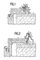
- the frame made of wood shown in FIG. 1 consists of a lining 2 lying in the wall opening of a wall 1 and at least one clothing 4 arranged at right angles on the edge of the lining and lying on the wall surface 3.
- a End strip 5 made of wood.
- a holding strip 6 is first attached to the clothing 4, which rests with a fastening leg 7 on the broad surface of the clothing 4 and is fastened to this fastening leg 7 by means of screws or nails 8. Fastening the retaining strip does not require that the clothing be made of wood.
- the retaining strip can also be fastened to clothing, for example, using so-called self-tapping screws, which consists, for example, of a hollow profile made of metal.
- the retaining strip 6 also has a push-on leg 9 which projects perpendicularly to the wide surface of the clothing or perpendicular to the wall surface 3 of the clothing 4.
- the end strip 5 is provided on the inside with a longitudinal groove-like recess 10 and is perpendicular to the wall surface 3 on the plug leg 9 of the retaining bar 6 self-locking.
- the holding strip 6 can be made of light metal, for example, and to increase the hold of the end strip 5 on the push-on leg 9, the latter can be provided with ribbing on one or both sides.
- the holding bar 6 can also be made Are made of plastic and have a hard core and a soft jacket in order to increase the clamping of the slip-on leg 9 in the groove-like recess 10.
- the end strip 5 is also provided on its inside facing the clothing with a cavity 11 into which that part of the retaining strip 6 which does not protrude into the groove-like recess 10 of the end strip 5 fits with enough space so that the end strip 5 after being attached the retaining strip 6 can fit snugly against the wide surface of the clothing 4 and can also be flush against the wall surface 3.
- the part of the wooden end strip 5 reaching up to the wall surface 3 can be shortened, for example, by planing and so adapted to the thickness of the clothing 4 that, when the end strip 5 lies snugly on the wide surface of the clothing 4, the adapted part of the end strip 5 is as free as possible of the Wall surface 3 reaches.
- the retaining strip 6 also has a stop leg 13 resting against the edge surface 12 of the clothing 4. The stop leg 13 facilitates dimensionally accurate fastening of the retaining strip 6 on the wide surface of the clothing 4.
- the retaining strip 6 could also be parallel to this stop leg 13 by means of screws or nails directed towards the wall surface 3 can be fastened to the clothing 4, wherein the fastening leg 7 can advantageously also be provided in order to support the retaining strip 6 on the clothing 4 in the plug-on direction of the end strip 5.
- subsequent fastening of the retaining strip 6 to the edge surface 12 of the clothing with screws or nails directed parallel to the wall surface 3 is not possible or is possible only with great difficulty.
- the attachment of the retaining strip 6 to the mounting leg 7 and on the wide surface of the clothing 4 by means of screws or hammered-in nails screwed in perpendicular to the wall surface 3 has the advantage that it is always light and unimpeded by an angular wall or the like can be made.
- the part of the end strip 5 which extends as far as the wall surface 3 is at a distance from the edge surface 12 of the clothing 4, so as to form a cavity which is closed by the end strip 5 and in which, for example, a telephone line or Bell line 14 can be laid, for which there is often a need.
- the retaining strip 6 is somewhat shorter at the ends than the end strip 5 to be clipped on.
- the ends of the vertical and the horizontal end strip which collide in a mitred corner of the frame can yield resiliently in the direction parallel to the wall surface. This ensures that the two end strips, if they are measured slightly longer than the nominal size, always lie on the mitred corner of the frame without play, with full contact.
- the end of the end strip can also bend somewhat resiliently in the direction perpendicular to the wall surface in order to be able to attach a lever under the end strip to completely pull off the end strip 5 from the holding strip 6.
- the end strip 20 consists of a hollow profile made, for example, by extrusion from plastic or from light metal.
- the inside groove-like recess 21, which is intended for inserting the plug-on leg 22 of the retaining strip 23, can be designed in such a way that the plug-on leg 22 formed with a thickened head 24 snaps into the groove-like recess 21 like a push button and the end strip 20 reliably on the clothing 4 and holds on to the wall surface 3.
- the retaining strip 6 or 23 can be attached to the clothing 4 exclusively or additionally by means of an adhesive connection.
Landscapes
- Engineering & Computer Science (AREA)
- Civil Engineering (AREA)
- Structural Engineering (AREA)
- Door And Window Frames Mounted To Openings (AREA)
- Supports Or Holders For Household Use (AREA)
- Patch Boards (AREA)
Abstract
Description
- Die Erfindung betrifft eine Umfassungszarge zur Verkleidung einer Wandöffnung für eine Tür oder dergleichen gemäß dem Oberbegriff des Anspruchs 1.
- Soweit es insbesondere bei Holzzargen bekannt ist, an der an sich aus einem Brett bestehenden Bekleidung aus optischen Gründen eine beliebig profilierte, die Bekleidung wulstartig umrandende Abschlußleiste vorzusehen, ist es gebräuchlich, die Abschlußleiste anzuleimen oder anzunageln, wobei die Nagellöcher verkittet werden. Die Abschlußleisten sind hiernach fest mit der Bekleidung der Zarge verbunden. Das nachträgliche Abnehmen der Abschlußleisten ist nicht oder nur sehr schwierig möglich und mit der Gefahr verbunden, daß die Abschlußleisten beschädigt oder zerstört werden. Wenn die Wohnung renoviert wird, zum Beispiel mit einem neuen Wandanstrich oder mit neuen Tapeten, müssen die Außenkanten der Zargen abgeklebt werden, um Beschädigungen und Verschmutzungen zu vermeiden.
- Die Erfindung hat zur Aufgabe, eine Umfassungszarge mit Abschlußleiste an der Bekleidung so auszubilden, daß die Abschlußleiste jederzeit ohne Schwierigkeiten abgenommen und nach einer Wandrenovierung wieder angebracht werden kann, um die Wand bis unter die Abschlußleiste mit einem neuen Anstrich oder einer neuen Tapete versehen zu können, und daß die Abschlußleiste als abnehmbare Tapetenleiste oder das Aussehen der Zarge verändernde Zierleiste auch nachträglich an schon eingebaute Türzargen mit einfachen Mitteln und ohne Schwierigkeiten angebracht werden kann.
- Diese Aufgabe wird gemäß der Erfindung durch die im kennzeichnenden Teil des Anspruchs 1 enthaltenen Merkmale gelöst. Die Erfindung wird anhand der Zeichnung näher beschrieben, in der zwei Ausführungsbeispiele dargestellt sind. Es zeigen
- Figur 1 einen Querschnitt durch ein erstes Ausführungsbeispiel,
- Figur 2 einen Querschnitt durch ein zweites Ausführungsbeispiel.
- Die in Figur 1 dargestellte Zarge aus Holz besteht aus einem in der Wandöffnung einer Wand 1 liegenden Futter 2 und wenigstens einer rechtwinklig am Rand des Futters angeordneten, auf der Wandoberfläche 3 liegenden Bekleidung 4. An dem dem Futter 2 abgekehrten Rand der Bekleidung 4 ist eine Abschlußleiste 5 aus Holz angeordnet. Zur abnehmbaren Verbindung der Abschlußleiste 5 mit der Bekleidung 4 ist an der Bekleidung 4 zunächst eine Halteleiste 6 angebracht, die mit einem Befestigungsschenkel 7 auf der Breitfläche der Bekleidung 4 aufliegt und an diesem Befestigungsschenkel 7 mittels Schrauben oder Nägeln 8 befestigt ist. Die Befestigung der Halteleiste setzt nicht voraus, daß die Bekleidung aus Holz besteht. Die Halteleiste kann zum Beispiel mit sogenannten Blechschrauben auch an einer Bekleidung befestigt werden, die zum Beispiel aus einem Hohlprofil aus Metall besteht. Die Halteleiste 6 besitzt weiterhin einen Aufsteckschenkel 9, der senkrecht zur Breitfläche der Bekleidung respektive senkrecht zur Wandoberfläche 3 von der Bekleidung 4 absteht. Die Abschlußleiste 5 ist innenseitig mit einer längs verlaufenden nutartigen Vertiefung 10 versehen und ist senkrecht zur Wandoberfläche 3 auf den Aufsteckschenkel 9 der Halteleiste 6 selbstklemmend aufsteckbar. Die Halteleiste 6 kann zum Beispiel aus Leichtmetall bestehen, und zur Erhöhung des Haltes der Abschlußleiste 5 auf dem Aufsteckschenkel 9 kann dieser einseitig oder beidseitig mit einer Riffelung versehen sein. Die Halteleiste 6 kann auch aus Kunststoff bestehen und hierbei einen harten Kern und einen weichen Mantel aufweisen, um die Einklemmung des Aufsteckschenkels 9 in der nutartigen Vertiefung 10 zu erhöhen. Die Abschlußleiste 5 ist ferner an ihrer der Bekleidung zugewendeten Innenseite mit einer Aushöhlung 11 versehen, in die derjenige Teil der Halteleiste 6, der nicht in die nutartige Vertiefung 10 der Abschlußleiste 5 hineinragt, mit genügendem Platz hineinpaßt, damit die Abschlußleiste 5 nach dem Aufstecken auf die Halteleiste 6 satt an der Breitfläche der Bekleidung 4 anliegen kann und auch bündig an der Wandoberfläche 3 anliegen kann. Der bis an die Wandoberfläche 3 heranreichende Teil der Holzabschlußleiste 5 kann zum Beispiel durch Abhobeln gekürzt und so der Dicke der Bekleidung 4 angepaßt werden, daß bei sattem Aufliegen der Abschlußleiste 5 auf der Breitfläche der Bekleidung 4 der angepaßte Teil der Abschlußleiste 5 möglichst fugenfrei an die Wandoberfläche 3 heranreicht. Gemäß einem besonders vorteilhaften Ausgestaltungsmerkmal besitzt die Halteleiste 6 weiterhin einen an der Randfläche 12 der Bekleidung 4 anliegenden Anschlagschenkel 13. Der Anschlagschenkel 13 erleichtert ein maßgenaues Befestigen der Halteleiste 6 auf der Breitfläche der Bekleidung 4. Die Halteleiste 6 könnte auch an diesem Anschlagschenkel 13 mittels parallel zur Wandoberfläche 3 gerichteter Schrauben oder Nägel an der Bekleidung 4 befestigt sein, wobei der Befestigungsschenkel 7 mit Vorteil noch vorgesehen sein kann, um die Halteleiste 6 in der Aufsteckrichtung der Abschlußleiste 5 auf der Bekleidung 4 abzustützen. Insbesondere bei einer nahe einer Winkelwand stehenden Türzarge ist aber eine nachträgliche Befestigung der Halteleiste 6 an der Randfläche 12 der Bekleidung mit parallel zur Wandoberfläche 3 gerichteten Schrauben oder Nägeln nicht oder nur sehr schwierig möglich. Die Befestigung der Halteleiste 6 an dem Befestigungsschenkel 7 und auf der Breitfläche der Bekleidung 4 mittels senkrecht zur Wandoberfläche 3 eingeschraubter Schrauben oder eingeschlagener Nägel hat den Vorzug, daß sie stets leicht und ohne Behinderung durch eine Winkelwand oder dergleichen vorgenommen werden kann. Gemäß einem weiteren Ausgestaltungsmerkmal weist der bis an die Wandoberfläche 3 heranreichende Teil der Abschlußleiste 5 einen Abstand von der Randfläche 12 der Bekleidung 4 auf, um so einen von der Abschlußleiste 5 verschlossenen Hohlraum zu bilden, in dem um die Türzarge herum zum Beispiel eine Telefonleitung oder Klingelleitung 14 verlegt werden kann, wofür häufig ein Bedürfnis besteht.
- Vorteilhafterweise ist die Halteleiste 6 an den Enden etwas kürzer als die aufzusteckende Abschlußleiste 5. Dadurch können die in einer Gehrungsecke der Zarge zusammenstoßenden Enden der vertikalen und der horizontalen Abschlußleiste in Richtung parallel zur Wandoberfläche federnd nachgeben. Damit wird erreicht, daß die beiden Abschlußleisten, wenn man sie geringfügig länger als das Sollmaß bemißt, an der Gehrungsecke der Zarge stets spielfrei, satt berührend aneinanderliegen. Ferner läßt sich daß Ende der Abschlußleiste auch in Richtung senkrecht zur Wandoberfläche etwas federnd abbiegen, um zum vollständigen Abziehen der Abschlußleiste 5 von der Halteleiste 6 einen Hebel unter die Abschlußleiste ansetzen zu können.
- Bei dem in der Figur 2 dargestellten Ausführungsbeispiel besteht die Abschlußleiste 20 aus einem zum Beispiel durch Strangpressen herstellbaren Hohlprofil aus Kunststoff oder auch aus Leichtmetall. Hierbei kann die innenseitige nutartige Vertiefung 21, die zum Einstecken des Aufsteckschenkels 22 der Halteleiste 23 bestimmt ist, so gestaltet sein, daß der mit einem verdickten Kopf 24 ausgebildete Aufsteckschenkel 22 druckknopfartig in die nutartige Vertiefung 21 einrastet und die Abschlußleiste 20 zuverlässig an die Bekleidung 4 und an die Wandoberfläche 3 herangezogen hält.
- Die Befestigung der Halteleiste 6 bzw. 23 an der Bekleidung 4 kann ausschließlich oder zusätzlich auch durch eine Klebeverbindung erfolgen.
Claims (3)
Priority Applications (1)
| Application Number | Priority Date | Filing Date | Title |
|---|---|---|---|
| AT88105776T ATE67555T1 (de) | 1987-05-05 | 1988-04-12 | Umfassungszarge zur verkleidung einer wandoeffnung fuer eine tuer oder dergleichen. |
Applications Claiming Priority (2)
| Application Number | Priority Date | Filing Date | Title |
|---|---|---|---|
| DE8706403U | 1987-05-05 | ||
| DE8706403U DE8706403U1 (de) | 1987-05-05 | 1987-05-05 | Umfassungszarge zur Verkleidung einer Wandöffnung für eine Tür od.dgl. |
Publications (2)
| Publication Number | Publication Date |
|---|---|
| EP0289816A1 true EP0289816A1 (de) | 1988-11-09 |
| EP0289816B1 EP0289816B1 (de) | 1991-09-18 |
Family
ID=6807666
Family Applications (1)
| Application Number | Title | Priority Date | Filing Date |
|---|---|---|---|
| EP88105776A Expired - Lifetime EP0289816B1 (de) | 1987-05-05 | 1988-04-12 | Umfassungszarge zur Verkleidung einer Wandöffnung für eine Tür oder dergleichen |
Country Status (6)
| Country | Link |
|---|---|
| US (1) | US4803815A (de) |
| EP (1) | EP0289816B1 (de) |
| JP (1) | JPS63280185A (de) |
| AT (1) | ATE67555T1 (de) |
| CA (1) | CA1290196C (de) |
| DE (2) | DE8706403U1 (de) |
Cited By (1)
| Publication number | Priority date | Publication date | Assignee | Title |
|---|---|---|---|---|
| EP0395777A1 (de) * | 1989-05-03 | 1990-11-07 | ALCO-Systeme GmbH | Anordnung zum Verhindern von Taupunktunterschreitungen im Bereich von Fensteranschlüssen |
Families Citing this family (12)
| Publication number | Priority date | Publication date | Assignee | Title |
|---|---|---|---|---|
| FR2623223A1 (fr) * | 1987-11-16 | 1989-05-19 | Brio | Moulure pour huisserie presentant un debord par rapport au plan de la cloison |
| US6276101B1 (en) | 1995-01-27 | 2001-08-21 | Tapco International Corporation | Door and window surround |
| US6212835B1 (en) | 1995-01-27 | 2001-04-10 | Tapco International Corporation | Decorative trim assemblies |
| US6725614B2 (en) * | 1995-01-27 | 2004-04-27 | Tapco International Corporation | Decorative trim assemblies |
| US6463707B1 (en) | 1995-01-27 | 2002-10-15 | Tapco International Inc. | Decorative trim assemblies |
| US6112481A (en) * | 1995-01-27 | 2000-09-05 | Tapco International | Door surround apparatus and method of assembly |
| AU692735B2 (en) * | 1996-06-04 | 1998-06-11 | Ercole D'Ercole | Architrave and skirting board system |
| US5987843A (en) * | 1997-11-26 | 1999-11-23 | Canfield; Fred C. | Composite door frame and method of making the same |
| US6295779B1 (en) | 1997-11-26 | 2001-10-02 | Fred C. Canfield | Composite frame member and method of making the same |
| USD424210S (en) * | 1999-07-01 | 2000-05-02 | Tapco International Corporation | Sunburst trim assembly |
| US7748179B2 (en) | 2004-01-16 | 2010-07-06 | Tapco International Corporation | Decorative molding |
| WO2006116108A2 (en) * | 2005-04-22 | 2006-11-02 | Redbox Automated Retail, L.L.C. | System and method for regulating vendible media products |
Citations (5)
| Publication number | Priority date | Publication date | Assignee | Title |
|---|---|---|---|---|
| US1520782A (en) * | 1923-09-24 | 1924-12-30 | Knapp Brothers Mfg Company | Wall construction |
| FR1478885A (fr) * | 1966-05-05 | 1967-04-28 | Ct Pal Holding A G | Encadrement pour portes et fenêtres |
| US3875713A (en) * | 1973-05-31 | 1975-04-08 | Ethyl Corp | Liner for covering intersecting surfaces |
| DE2518765A1 (de) * | 1975-04-26 | 1976-10-28 | Karl Roth | Tuerfutter mit zwei beidseits angeordneten falzverkleidungen |
| DE3202833A1 (de) * | 1981-02-03 | 1982-10-28 | Portas Deutschland GmbH, 6057 Dietzenbach | Verkleidung fuer eine in einem bauwerk befestigte zarge fuer eine zimmer- oder haustuere oder dgl. |
Family Cites Families (5)
| Publication number | Priority date | Publication date | Assignee | Title |
|---|---|---|---|---|
| US2939188A (en) * | 1959-02-02 | 1960-06-07 | James A Wahlfeld | Storm window casing |
| US3271902A (en) * | 1964-04-22 | 1966-09-13 | Rolscreen Co | Window sill and sash construction |
| DE6752892U (de) * | 1968-09-03 | 1969-03-20 | Rudolf Dans Schreinermeister | Tuerfutter |
| DE7013929U (de) * | 1970-04-16 | 1970-09-24 | Schock & Co Gmbh | Tuerfutter. |
| US4505080A (en) * | 1980-07-24 | 1985-03-19 | Sailor Vernon R | Door or window frame assembly |
-
1987
- 1987-05-05 DE DE8706403U patent/DE8706403U1/de not_active Expired
-
1988
- 1988-04-12 DE DE8888105776T patent/DE3864893D1/de not_active Expired - Fee Related
- 1988-04-12 EP EP88105776A patent/EP0289816B1/de not_active Expired - Lifetime
- 1988-04-12 AT AT88105776T patent/ATE67555T1/de not_active IP Right Cessation
- 1988-04-26 JP JP63101513A patent/JPS63280185A/ja active Pending
- 1988-04-29 US US07/188,289 patent/US4803815A/en not_active Expired - Fee Related
- 1988-05-04 CA CA000565908A patent/CA1290196C/en not_active Expired - Lifetime
Patent Citations (5)
| Publication number | Priority date | Publication date | Assignee | Title |
|---|---|---|---|---|
| US1520782A (en) * | 1923-09-24 | 1924-12-30 | Knapp Brothers Mfg Company | Wall construction |
| FR1478885A (fr) * | 1966-05-05 | 1967-04-28 | Ct Pal Holding A G | Encadrement pour portes et fenêtres |
| US3875713A (en) * | 1973-05-31 | 1975-04-08 | Ethyl Corp | Liner for covering intersecting surfaces |
| DE2518765A1 (de) * | 1975-04-26 | 1976-10-28 | Karl Roth | Tuerfutter mit zwei beidseits angeordneten falzverkleidungen |
| DE3202833A1 (de) * | 1981-02-03 | 1982-10-28 | Portas Deutschland GmbH, 6057 Dietzenbach | Verkleidung fuer eine in einem bauwerk befestigte zarge fuer eine zimmer- oder haustuere oder dgl. |
Cited By (1)
| Publication number | Priority date | Publication date | Assignee | Title |
|---|---|---|---|---|
| EP0395777A1 (de) * | 1989-05-03 | 1990-11-07 | ALCO-Systeme GmbH | Anordnung zum Verhindern von Taupunktunterschreitungen im Bereich von Fensteranschlüssen |
Also Published As
| Publication number | Publication date |
|---|---|
| JPS63280185A (ja) | 1988-11-17 |
| US4803815A (en) | 1989-02-14 |
| DE8706403U1 (de) | 1987-09-03 |
| ATE67555T1 (de) | 1991-10-15 |
| CA1290196C (en) | 1991-10-08 |
| EP0289816B1 (de) | 1991-09-18 |
| DE3864893D1 (de) | 1991-10-24 |
Similar Documents
| Publication | Publication Date | Title |
|---|---|---|
| EP0289816B1 (de) | Umfassungszarge zur Verkleidung einer Wandöffnung für eine Tür oder dergleichen | |
| EP0801189A1 (de) | Laibungsanschlussprofil für Fenster- und Türoffnungen | |
| DE2853092A1 (de) | An einer wand mit einem halter befestigbare fussleiste | |
| EP0649617B1 (de) | Befestigungsvorrichtung für insbesondere Sockelblenden für Schrankmöbel | |
| EP3293323A1 (de) | Montagesystem für fussbodensockel oder fussbodenleiste | |
| DE10220049A1 (de) | Vorrichtung zur Befestigung von Sockelleisten | |
| DE3202833C2 (de) | Verkleidung für eine in einer Wandöffnung befestigte Zarge einer Haus- oder Zimmertür oder dergleichen | |
| DE2723287A1 (de) | Scheuer-, bzw. sockelleiste, vorzugsweise aus synthetischem material | |
| EP0036466B1 (de) | Fensterrahmen | |
| DE803658C (de) | Montagehilfsvorrichtung fuer elektrische in die Wand oder in den Putz versenkt angeordnete Installationsgeraete | |
| EP0605068A1 (de) | Rahmenhalterung zum Schliessen von Öffnungen | |
| DE4226686C1 (de) | Leiste zum Anbringen in Maueröffnungen | |
| DE2243277A1 (de) | Rolladenkasten mit unterer abdeckplatte | |
| AT394615B (de) | Fertigzarge mit nachtraeglich angebrachten zargenzierleisten | |
| DE19741526A1 (de) | Türzarge | |
| DE2103715A1 (de) | Abdeckleiste | |
| DE4237820C2 (de) | Leibungsverkleidung für Fenster oder Türen | |
| DE19514150A1 (de) | Anschlußfutter für einen Fensterrahmen | |
| DE3519535A1 (de) | Rahmen zum einfassen einer ausnehmung und zum umfassen einer abnehmbaren abdeckung fuer diese ausnehmung | |
| DE102017110329A1 (de) | Montagewerkzeug und Verfahren zur Montage einer Führungsschiene an einem plattenförmigen Möbelteil | |
| CH510194A (de) | Einbautür | |
| DE4402176A1 (de) | Leistenartiges Abdeckelement, insbesondere Wand-, Decken- oder Fußabschlußleiste | |
| DE29607863U1 (de) | Profilleiste aus Kunststoff, insbesondere für Wohnwageneinbauten | |
| CH550929A (de) | Zwischen fensterrahmen und mauerwerk anzuordnen bestimmte abschlussleiste. | |
| DE9210796U1 (de) | Leiste zum Anbringen von Maueröffnungen |
Legal Events
| Date | Code | Title | Description |
|---|---|---|---|
| PUAI | Public reference made under article 153(3) epc to a published international application that has entered the european phase |
Free format text: ORIGINAL CODE: 0009012 |
|
| AK | Designated contracting states |
Kind code of ref document: A1 Designated state(s): AT BE CH DE ES FR GB GR IT LI NL |
|
| 17P | Request for examination filed |
Effective date: 19890417 |
|
| 17Q | First examination report despatched |
Effective date: 19900829 |
|
| GRAA | (expected) grant |
Free format text: ORIGINAL CODE: 0009210 |
|
| AK | Designated contracting states |
Kind code of ref document: B1 Designated state(s): AT BE CH DE ES FR GB GR IT LI NL |
|
| PG25 | Lapsed in a contracting state [announced via postgrant information from national office to epo] |
Ref country code: NL Effective date: 19910918 Ref country code: GR Free format text: LAPSE BECAUSE OF FAILURE TO SUBMIT A TRANSLATION OF THE DESCRIPTION OR TO PAY THE FEE WITHIN THE PRESCRIBED TIME-LIMIT Effective date: 19910918 Ref country code: ES Free format text: THE PATENT HAS BEEN ANNULLED BY A DECISION OF A NATIONAL AUTHORITY Effective date: 19910918 |
|
| REF | Corresponds to: |
Ref document number: 67555 Country of ref document: AT Date of ref document: 19911015 Kind code of ref document: T |
|
| REF | Corresponds to: |
Ref document number: 3864893 Country of ref document: DE Date of ref document: 19911024 |
|
| GBT | Gb: translation of ep patent filed (gb section 77(6)(a)/1977) | ||
| ET | Fr: translation filed | ||
| ITF | It: translation for a ep patent filed | ||
| NLV1 | Nl: lapsed or annulled due to failure to fulfill the requirements of art. 29p and 29m of the patents act | ||
| PLBE | No opposition filed within time limit |
Free format text: ORIGINAL CODE: 0009261 |
|
| STAA | Information on the status of an ep patent application or granted ep patent |
Free format text: STATUS: NO OPPOSITION FILED WITHIN TIME LIMIT |
|
| 26N | No opposition filed | ||
| PGFP | Annual fee paid to national office [announced via postgrant information from national office to epo] |
Ref country code: GB Payment date: 19930308 Year of fee payment: 6 |
|
| PGFP | Annual fee paid to national office [announced via postgrant information from national office to epo] |
Ref country code: BE Payment date: 19930414 Year of fee payment: 6 Ref country code: AT Payment date: 19930414 Year of fee payment: 6 |
|
| PGFP | Annual fee paid to national office [announced via postgrant information from national office to epo] |
Ref country code: FR Payment date: 19940207 Year of fee payment: 7 |
|
| PGFP | Annual fee paid to national office [announced via postgrant information from national office to epo] |
Ref country code: DE Payment date: 19940211 Year of fee payment: 7 |
|
| PG25 | Lapsed in a contracting state [announced via postgrant information from national office to epo] |
Ref country code: GB Effective date: 19940412 Ref country code: AT Effective date: 19940412 |
|
| PGFP | Annual fee paid to national office [announced via postgrant information from national office to epo] |
Ref country code: CH Payment date: 19940418 Year of fee payment: 7 |
|
| PG25 | Lapsed in a contracting state [announced via postgrant information from national office to epo] |
Ref country code: BE Effective date: 19940430 |
|
| BERE | Be: lapsed |
Owner name: S.A. EUROPATENT Effective date: 19940430 |
|
| GBPC | Gb: european patent ceased through non-payment of renewal fee |
Effective date: 19940412 |
|
| PG25 | Lapsed in a contracting state [announced via postgrant information from national office to epo] |
Ref country code: LI Effective date: 19950430 Ref country code: CH Effective date: 19950430 |
|
| REG | Reference to a national code |
Ref country code: CH Ref legal event code: PL |
|
| PG25 | Lapsed in a contracting state [announced via postgrant information from national office to epo] |
Ref country code: FR Effective date: 19951229 |
|
| PG25 | Lapsed in a contracting state [announced via postgrant information from national office to epo] |
Ref country code: DE Effective date: 19960103 |
|
| REG | Reference to a national code |
Ref country code: FR Ref legal event code: ST |
|
| PG25 | Lapsed in a contracting state [announced via postgrant information from national office to epo] |
Ref country code: IT Free format text: LAPSE BECAUSE OF NON-PAYMENT OF DUE FEES;WARNING: LAPSES OF ITALIAN PATENTS WITH EFFECTIVE DATE BEFORE 2007 MAY HAVE OCCURRED AT ANY TIME BEFORE 2007. THE CORRECT EFFECTIVE DATE MAY BE DIFFERENT FROM THE ONE RECORDED. Effective date: 20050412 |