EP0289907A1 - Dispositif pour la combustion contrôlée d'un mélange détonable air-hydrogène dans le confinement de réacteurs nucléaires refroidis à l'eau - Google Patents
Dispositif pour la combustion contrôlée d'un mélange détonable air-hydrogène dans le confinement de réacteurs nucléaires refroidis à l'eau Download PDFInfo
- Publication number
- EP0289907A1 EP0289907A1 EP88106613A EP88106613A EP0289907A1 EP 0289907 A1 EP0289907 A1 EP 0289907A1 EP 88106613 A EP88106613 A EP 88106613A EP 88106613 A EP88106613 A EP 88106613A EP 0289907 A1 EP0289907 A1 EP 0289907A1
- Authority
- EP
- European Patent Office
- Prior art keywords
- spring
- energy store
- ignition
- temperature
- ignition source
- Prior art date
- Legal status (The legal status is an assumption and is not a legal conclusion. Google has not performed a legal analysis and makes no representation as to the accuracy of the status listed.)
- Granted
Links
Images

Classifications
-
- G—PHYSICS
- G21—NUCLEAR PHYSICS; NUCLEAR ENGINEERING
- G21C—NUCLEAR REACTORS
- G21C19/00—Arrangements for treating, for handling, or for facilitating the handling of, fuel or other materials which are used within the reactor, e.g. within its pressure vessel
- G21C19/28—Arrangements for introducing fluent material into the reactor core; Arrangements for removing fluent material from the reactor core
- G21C19/30—Arrangements for introducing fluent material into the reactor core; Arrangements for removing fluent material from the reactor core with continuous purification of circulating fluent material, e.g. by extraction of fission products deterioration or corrosion products, impurities, e.g. by cold traps
- G21C19/317—Recombination devices for radiolytic dissociation products
-
- F—MECHANICAL ENGINEERING; LIGHTING; HEATING; WEAPONS; BLASTING
- F23—COMBUSTION APPARATUS; COMBUSTION PROCESSES
- F23Q—IGNITION; EXTINGUISHING-DEVICES
- F23Q3/00—Igniters using electrically-produced sparks
-
- Y—GENERAL TAGGING OF NEW TECHNOLOGICAL DEVELOPMENTS; GENERAL TAGGING OF CROSS-SECTIONAL TECHNOLOGIES SPANNING OVER SEVERAL SECTIONS OF THE IPC; TECHNICAL SUBJECTS COVERED BY FORMER USPC CROSS-REFERENCE ART COLLECTIONS [XRACs] AND DIGESTS
- Y02—TECHNOLOGIES OR APPLICATIONS FOR MITIGATION OR ADAPTATION AGAINST CLIMATE CHANGE
- Y02E—REDUCTION OF GREENHOUSE GAS [GHG] EMISSIONS, RELATED TO ENERGY GENERATION, TRANSMISSION OR DISTRIBUTION
- Y02E30/00—Energy generation of nuclear origin
- Y02E30/30—Nuclear fission reactors
Definitions
- the invention relates to a device for the controlled combustion of ignitable hydrogen-air mixtures in the containment of water-cooled nuclear reactor plants, with at least one ignition source.
- ignitable hydrogen-air mixtures can occur in the safety tank of light water reactors.
- a serious accident is understood to mean the nuclear meltdown that is very unlikely in modern light water reactors.
- a preliminary stage of this occurred in the 1979 TMI accident in the USA.
- the overheating of the fuel elements in the upper area of the core came to a standstill, and a large amount of hydrogen gas which was enclosed in the containment could be removed without endangering the adjacent areas. If such gas mixtures are ignited at high H2 concentrations in an uncontrolled manner, the reactor safety container is additionally burdened by explosion pressure and temperature.
- the targeted, early ignition of the H2-air mixtures at a low H2 concentration minimizes these loads and prevents the safety container from leaking.
- H2 and O2 are passed through sintered, porous copper plates, which are traversed by cooling tubes, and burn on and in these porous copper plates, an inflow chamber and an outflow chamber (where the water vapor occurs) through such sintered porous, cooled copper plates to the outside or are sealed off from each other.
- This water-cooled burner requires at least one ignition source, it is particularly suitable for boiling water nuclear reactor plants, where not only in the event of a malfunction, but also due to radiolysis, amounts of hydrogen to be eliminated arise during normal operation.
- DE-PS 30 04 677 From DE-PS 30 04 677 it is known to arrange ignition sources in all areas of the security container in which hydrogen can occur, which are arranged in a grid, the distance of which is dependent on the hazard potential of the respective area.
- this measure which is self-evident (also in the subject of DE-OS 20 16 800, several ignition sources with several burners are provided, which of course also have to work in the event of a serious accident), glow plugs, spark plugs or catalytic ignition sources are used as ignition sources.
- Catalytic ignition sources are subject to contamination and therefore the special problem of whether they really work in an emergency. Glow plugs and spark plugs require a power supply via cable, usually from the emergency power supply, but this can also fail in the aforementioned malfunction.
- the invention has for its object to design the generic device so that it manages with a wireless power supply and in any case its function efficiency is guaranteed in the event of a fault.
- the object is achieved in a device according to the preamble of claim 1 by the features specified in the characterizing part of claim 1.
- Self-sufficient is understood to mean that the energy store does not require any supply lines, be it cables or other energy transport lines, so that there is no dependency on a remote energy store. Rather, this is directly assigned to the ignition source. If the energy store is a dry battery, electrical remote monitoring of its state of charge is possible in a simple manner. However, it is also possible to use a small glow lamp at the location of the ignition source to display the state of charge in a manageable manner.
- the energy storage is the dry battery of a high-voltage ignition unit with a spring-loaded switch in the circuit of the dry battery, as well as with a high-voltage module, charging capacitor and spark igniter, and that the temperature-dependent trigger element is set up to close the spring-loaded switch in the event of a response.
- high-voltage ignition units are already commercially available in a variety of embodiments, for example for electron flash devices. It is necessary that the aforementioned elements, with the exception of the temperature-dependent triggering element, are protected against moisture, pressure and temperature within a housing, in particular a metal housing, and are wired. The wall of the housing is only penetrated by the spark igniter, a switch pin and possibly by test sockets (for checking the charge of the dry battery).
- a quickly responding sprinkler element serves as a trigger element, which has a wall, skin or membrane bursting when a temperature limit value is reached, which then Response latch releases the energy store for discharge or the spring-loaded switch for closing.
- a bimetal arrangement can also be provided as a temperature-dependent triggering element, which releases or actuates the spring-loaded switch for closing when a temperature limit value is reached.
- a lithium chloride cell is an electrochemical secondary element of considerably higher specific energy and charge density than conventional accumulators.
- the lithium chloride cell contains e.g.
- the plus line 1.1 and the minus line 1.2 of a dry cell 1 are connected to the input terminals 4.1, 4.2 of a high-voltage module 4, a spring-loaded switch 2 being switched on in the minus line 1.2, which is operatively connected to the trigger element 3 of a (not shown in more detail) ) Fast response sprinklers is brought.
- the spark gap 6a-6b of an electrical spark igniter 6 is via the electrical high Voltage lines 6.1 and 6.2 are connected, a charging resistor 8 being arranged in the line part 6.1 and the two lines 6.1, 6.2 being connected to one another by a charging capacitor 5 between the charging resistor and spark gap 6.
- the spark igniter 6 is provided with a splash guard 7.
- all components of this ignition source designated as a whole with Z1, with the exception of the sprinkler element 3, an associated switching pin and the spark igniter 6 are protected from moisture, pressure and temperature within a metal housing 9 and wired therein.
- the wall of the metal housing is only penetrated by the electrical leads of the spark igniter 6, the aforementioned switching pin of the sprinkler element and possibly by test sockets (for charging control of the dry cell) in a pressure and moisture-proof manner.
- a practical version of the ignition source Z1 takes up a volume of approximately 2 dm.
- the spring-loaded switch 2 is shifted into its closed position by the spring indicated by a black arrow 2.0, and the high-voltage module 4 is supplied with direct current by the dry cell 1.
- the high voltage generated in this high-voltage module 4 is removed from the outer ignition circuit at terminals 4.3, 4.4 and generates a sawtooth-shaped ignition high voltage at the two ignition electrodes 6a, 6b via the RC combination 8.5.
- the cycle time can be several minutes because after a hydrogen volume has been flared, a certain time passes until an ignitable mixture is present again.
- the battery 1 has such a capacity that the clocking ignition processes can extend over several days.
- the high-voltage module 4 is an electronic unit which transforms the voltage from the low-voltage dry cell 1 to the required spark voltage. It converts the direct current into a transformable impulse current.
- the ignition source Z1 according to FIG. 1 could be used instead of an electronic one
- a mechanical breaker can also be provided.
- the transistor 11 If the transistor 11 is blocked by a corresponding base bias, a high ignition voltage is induced in the secondary high-voltage winding 12b, which discharges as an ignition spark on the spark gap 6.
- the transistor 11 works similarly to that of a transistor ignition in a motor vehicle.
- sprinkler systems are automatic fire extinguishing systems with spray nozzles for the extinguishing agent water which are distributed over the rooms to be protected, and are used to combat incipient fires. They are triggered by the fire heat on site by destroying the closure of a spray nozzle - the sprinkler head.
- hot gas-steam mixtures which are present in the containment in the event of a fault are also suitable as the triggering heat.
- the closures of the sprinkler spray nozzle consist either of fusible links or glass vials and can be manufactured for different trigger temperatures. Usually the trigger temperature is chosen to be 50 K above normal room temperature lies.
- FIG. 3 schematically shows a sprinkler element 3 with a cylindrical glass barrel 14, which is pressed against the seat surfaces 16.1 of an opening 16 in the wall 17 of a sprinkler container by a screw cap 15 which is open in the manner of a basket or cage or provided with, for example, side convection openings 15.1.
- the movable contacts 20.1 are opposed to fixed contacts 21.1 and 21.2, the openable or closable contact path 21.1-21.2 in cooperation with the contact bridge 20.1 being able to form the spring-loaded switch 2 according to FIG. 1 and FIG. 2.
- the channel 16.1 and the opened opening 16 are otherwise used to introduce extinguishing water under pressure from a sprinkler reservoir, not shown, the water exiting in the form of a wide-spread extinguishing cone through nozzle openings in the screw cap; here, however, the sprinkler element shown is converted to a temperature-dependent quick-closing switch for the ignition source Z1 or Z2.
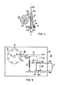
- a bimetallic arrangement 3 'according to FIG. 4 can also serve as a temperature-dependent triggering element for the spring-loaded switch 2.
- the inner end 23.1 of the bimetal spiral 23 serves both as a clamping point and as the one switch contact.
- the free end 23.2 of the bimetal spiral 23 carries a double contact 24.1, 24.2 which, in the position I shown, bears against an empty contact 25.0.
- the bimetal spiral has warmed up so much that due to the greater thermal expansion of the outer metal strip 23a (compared to the lower thermal expansion of the inner metal strip 23b), the free end 23.2 of the bimetal spiral 23 has stretched somewhat and thereby comes into contact with the system the counter contact 25 has come.
- a sufficient contact pressure and an accentuated switching movement is achieved by a dead center spring 26 attached at 26.1. This engages at the free end of a sheet metal strip 27 connected to the two bimetallic strips 23a, 23b and 27.1 with cutting edges (this is indicated by dash-dotted lines). The setting is made so that the two contact positions I and II are stable dead center positions.
- a dry battery as an energy store can be dispensed with, in that at least one piezo crystal 28 with a pressure bearing is used as the ignition source Z3, with a spark gap 6 connected to its two preferably metallized poles 28.1, 28.2, the energy store being an organ 29 for Exercise periodic pressure loads on the piezo crystal 28 in response.
- a cam wheel 31 with cams 31.1 is placed on a rotatable shaft 30 driven by a spiral spring (not shown).
- the pivotable angle lever 32 is pivotably mounted at 32.0 in the direction of the arrow ⁇ f1 and is pulled by a spiral spring 33 with its hammer head 32.1 in the direction of the piezo crystal 28.
- the hammer surface coming into contact with the top surface 28.1 of the piezo crystal 28 is, as shown, slightly beveled so that a large-area contact is ensured in the event of contact.
- the swivel circle k about the swivel axis 32.0 of the angle lever 32 indicates that when the cam disk 31 rotates in the direction of the arrow f2, the angle lever 32 is first swiveled in the direction + f1 and after a specific driving path which is approximately the distance between two neighboring cams 31.1 corresponds, disengages the cams 31.1 and is thus pivoted back in the direction - f1 by the tension spring 33 until the hammer surface 32.3 strikes the piezo crystal 28.
- the piezo crystal 28 is therefore periodically subjected to pressure.
- the spring accumulator (not shown in more detail) for rotating the cam wheel 31 can be provided in the manner of a clockwork with a restlessness to even out the rotation of the cam disk 31. It is expediently dimensioned so large that it has a sufficient power reserve for four to five days for the rotation of the cam disk 31.
- the piezo crystal 28 is held and stored in a pressure-resistant bearing 34.
- the tension spring 33 also engages at this end.
- the entire deflection gear 29 is accommodated in a housing 35 which is resistant to accidents and is pressure-tight and water-protected; only the spark gap 6 with its two ignition electrodes is attached to the outside of the housing 35 and is insulated with its electrical feed lines 6a1, 6a2 and passed through the side wall of the housing 35 in a pressure-tight manner.
- a polygon or polygon which is accessible from the outside, can be provided for attaching a wrench for the spring accumulator (not shown).
- the discharge of the spring accumulator can be triggered, for example, by a sprinkler trigger element, as explained with reference to FIGS. 1 to 3, or by a bimetal trigger element according to FIG. 4.
Landscapes
- Engineering & Computer Science (AREA)
- General Engineering & Computer Science (AREA)
- Physics & Mathematics (AREA)
- Chemical & Material Sciences (AREA)
- Combustion & Propulsion (AREA)
- Mechanical Engineering (AREA)
- Plasma & Fusion (AREA)
- High Energy & Nuclear Physics (AREA)
- Fire-Extinguishing By Fire Departments, And Fire-Extinguishing Equipment And Control Thereof (AREA)
- Disinfection, Sterilisation Or Deodorisation Of Air (AREA)
- Hydrogen, Water And Hydrids (AREA)
- Air Bags (AREA)
Applications Claiming Priority (2)
| Application Number | Priority Date | Filing Date | Title |
|---|---|---|---|
| DE3715469 | 1987-05-08 | ||
| DE3715469 | 1987-05-08 |
Publications (2)
| Publication Number | Publication Date |
|---|---|
| EP0289907A1 true EP0289907A1 (fr) | 1988-11-09 |
| EP0289907B1 EP0289907B1 (fr) | 1992-07-08 |
Family
ID=6327150
Family Applications (1)
| Application Number | Title | Priority Date | Filing Date |
|---|---|---|---|
| EP88106613A Expired - Lifetime EP0289907B1 (fr) | 1987-05-08 | 1988-04-25 | Dispositif pour la combustion contrôlée d'un mélange détonable air-hydrogène dans le confinement de réacteurs nucléaires refroidis à l'eau |
Country Status (6)
| Country | Link |
|---|---|
| US (1) | US4891181A (fr) |
| EP (1) | EP0289907B1 (fr) |
| JP (1) | JPS63286799A (fr) |
| DE (1) | DE3872589D1 (fr) |
| ES (1) | ES2033360T3 (fr) |
| FI (1) | FI87613C (fr) |
Cited By (3)
| Publication number | Priority date | Publication date | Assignee | Title |
|---|---|---|---|---|
| EP0342602A1 (fr) * | 1988-05-17 | 1989-11-23 | Siemens Aktiengesellschaft | Dispositif pour la combustion contrôlée d'un mélange détonant hydrogène-air dans une installation nucléaire |
| WO1998054731A1 (fr) * | 1997-05-27 | 1998-12-03 | Siemens Aktiengesellschaft | Systeme d'amorcage pour recombiner de l'hydrogene dans un melange gazeux et enceinte de confinement d'une installation nucleaire |
| WO2017129425A2 (fr) | 2016-01-25 | 2017-08-03 | Cci Ag | Installation comprenant un contenant de réacteur, une conduite sous pression et un dispositif d'inflammation, et procédé pour faire fonctionner l'installation |
Families Citing this family (4)
| Publication number | Priority date | Publication date | Assignee | Title |
|---|---|---|---|---|
| DE19544346C1 (de) * | 1995-11-28 | 1997-04-03 | Siemens Ag | Sicherheitsbehälter eines Kernkraftwerkes |
| DE102007059827B3 (de) * | 2007-12-11 | 2008-11-20 | Areva Np Gmbh | Sicherheitssystem ein kerntechnischen Anlage |
| DE102007060372B4 (de) | 2007-12-12 | 2010-11-18 | Areva Np Gmbh | Rekombinatorelement |
| US10839966B2 (en) * | 2017-05-10 | 2020-11-17 | Westinghouse Electric Company Llc | Vortex driven passive hydrogen recombiner and igniter |
Citations (4)
| Publication number | Priority date | Publication date | Assignee | Title |
|---|---|---|---|---|
| US2856564A (en) * | 1956-01-31 | 1958-10-14 | John W Derwin | Barium titanate crystals as a portable source of electric power |
| FR2198095A1 (fr) * | 1972-09-06 | 1974-03-29 | Braun Ag | |
| DE3004677A1 (de) * | 1980-02-08 | 1981-08-27 | Babcock-Brown Boveri Reaktor Gmbh, 6800 Mannheim | Verfahren und einrichtung zum abbau des im sicherheitsbehaelter einer wassergekuehlten kernreaktoranlage eingeschlossenen wasserstoffs |
| US4425495A (en) * | 1982-12-10 | 1984-01-10 | Morrison-Knudsen Company, Inc. | Ignitor and enclosure structure |
Family Cites Families (11)
| Publication number | Priority date | Publication date | Assignee | Title |
|---|---|---|---|---|
| US3307913A (en) * | 1962-07-27 | 1967-03-07 | Stone & Webster Eng Corp | Vacuum producing apparatus for containment vessels |
| US3740313A (en) * | 1968-10-29 | 1973-06-19 | Gen Electric | Burner-flame arrester for burning offgas from a boiling water reactorpower plant |
| US3658996A (en) * | 1969-02-03 | 1972-04-25 | Westinghouse Electric Corp | System for the removal of hydrogen from nuclear containment structures |
| US3598699A (en) * | 1969-04-09 | 1971-08-10 | Gen Electric | Nuclear reactor off-gas burner system |
| US4139603A (en) * | 1971-09-09 | 1979-02-13 | Westinghouse Electric Corp. | Hydrogen-oxygen recombiner |
| BE788538A (fr) * | 1971-09-09 | 1973-03-08 | Westinghouse Electric Corp | Appareil de recombinaison de l'hydrogene et de l'oxygene |
| DE2243694A1 (de) * | 1972-09-06 | 1974-03-14 | Braun Ag | Batteriezuendvorrichtung |
| DE2317940A1 (de) * | 1973-04-10 | 1974-10-24 | Braun Ag | Starteinrichtung fuer batteriezuendvorrichtung |
| DD152224A1 (de) * | 1980-07-16 | 1981-11-18 | Eberhard Fritz | Anordnung zum abbauen eines in einer druckkammer entstandenen drucks |
| US4452582A (en) * | 1982-06-18 | 1984-06-05 | Portasik John P | Independent, self-contained electronic spark ignition recycler |
| US4741879A (en) * | 1986-06-10 | 1988-05-03 | The United States Of America As Represented By The United States Department Of Energy | Catalytic igniters and their use to ignite lean hydrogen-air mixtures |
-
1988
- 1988-04-25 FI FI881934A patent/FI87613C/fi not_active IP Right Cessation
- 1988-04-25 DE DE8888106613T patent/DE3872589D1/de not_active Expired - Lifetime
- 1988-04-25 ES ES198888106613T patent/ES2033360T3/es not_active Expired - Lifetime
- 1988-04-25 EP EP88106613A patent/EP0289907B1/fr not_active Expired - Lifetime
- 1988-05-02 JP JP63109799A patent/JPS63286799A/ja active Pending
- 1988-05-06 US US07/191,274 patent/US4891181A/en not_active Expired - Lifetime
Patent Citations (4)
| Publication number | Priority date | Publication date | Assignee | Title |
|---|---|---|---|---|
| US2856564A (en) * | 1956-01-31 | 1958-10-14 | John W Derwin | Barium titanate crystals as a portable source of electric power |
| FR2198095A1 (fr) * | 1972-09-06 | 1974-03-29 | Braun Ag | |
| DE3004677A1 (de) * | 1980-02-08 | 1981-08-27 | Babcock-Brown Boveri Reaktor Gmbh, 6800 Mannheim | Verfahren und einrichtung zum abbau des im sicherheitsbehaelter einer wassergekuehlten kernreaktoranlage eingeschlossenen wasserstoffs |
| US4425495A (en) * | 1982-12-10 | 1984-01-10 | Morrison-Knudsen Company, Inc. | Ignitor and enclosure structure |
Cited By (6)
| Publication number | Priority date | Publication date | Assignee | Title |
|---|---|---|---|---|
| EP0342602A1 (fr) * | 1988-05-17 | 1989-11-23 | Siemens Aktiengesellschaft | Dispositif pour la combustion contrôlée d'un mélange détonant hydrogène-air dans une installation nucléaire |
| WO1989011721A1 (fr) * | 1988-05-17 | 1989-11-30 | Siemens Aktiengesellschaft | Dispositif pour la combustion controlee d'un melange hydrogene/air inflammable dans une installation nucleaire |
| US5108696A (en) * | 1988-05-17 | 1992-04-28 | Siemens Aktiengesellschaft | Device for controlled combustion of an ignitable hydrogen/air mixture in a nuclear power plant |
| WO1998054731A1 (fr) * | 1997-05-27 | 1998-12-03 | Siemens Aktiengesellschaft | Systeme d'amorcage pour recombiner de l'hydrogene dans un melange gazeux et enceinte de confinement d'une installation nucleaire |
| US6385270B1 (en) | 1997-05-27 | 2002-05-07 | Siemens Aktiengellschaft | Safety vessel of a nuclear facility having an ignition system for the recombination of hydrogen in a gas mixture |
| WO2017129425A2 (fr) | 2016-01-25 | 2017-08-03 | Cci Ag | Installation comprenant un contenant de réacteur, une conduite sous pression et un dispositif d'inflammation, et procédé pour faire fonctionner l'installation |
Also Published As
| Publication number | Publication date |
|---|---|
| FI87613C (fi) | 1993-01-25 |
| US4891181A (en) | 1990-01-02 |
| ES2033360T3 (es) | 1993-03-16 |
| DE3872589D1 (de) | 1992-08-13 |
| FI881934A7 (fi) | 1988-11-09 |
| FI87613B (fi) | 1992-10-15 |
| EP0289907B1 (fr) | 1992-07-08 |
| FI881934A0 (fi) | 1988-04-25 |
| JPS63286799A (ja) | 1988-11-24 |
Similar Documents
| Publication | Publication Date | Title |
|---|---|---|
| DE1248374C2 (de) | Antriebsvorrichtung mit einem Strahltriebwerk | |
| EP0289907B1 (fr) | Dispositif pour la combustion contrôlée d'un mélange détonable air-hydrogène dans le confinement de réacteurs nucléaires refroidis à l'eau | |
| EP1137895A1 (fr) | Procede et dispositif permettant de transformer les gaz s'echappant par evaporation des cryo-reservoirs | |
| EP4184692A2 (fr) | Système de batterie | |
| EP0342602B1 (fr) | Dispositif pour la combustion contrôlée d'un mélange détonant hydrogène-air dans une installation nucléaire | |
| EP0838240A2 (fr) | Installation d'extinction d'incendie | |
| DE102020120041A1 (de) | Batteriesystem und Kraftfahrzeug mit einem Batteriesystem | |
| DE102012021095A1 (de) | Akkumulator für ein Fahrzeug mit Notlöscheinrichtung | |
| DE19722165C1 (de) | Zündsystem zur Rekombination von Wasserstoff in einem Gasgemisch und Sicherheitsbehälter einer kerntechnischen Anlage | |
| DE102019127909A1 (de) | Batterie | |
| DE69301252T2 (de) | Zündungs- und Heizungsvorrichtung | |
| EP0466052A1 (fr) | Procédé de réduction des risques en cas d'accident | |
| DE816626C (de) | Treibgasgenerator, z. B. fuer Raketenantriebe | |
| WO1989012897A1 (fr) | Procede et dispositif pour evacuer un melange gazeux inflammable d'une enceinte | |
| EP3718123A1 (fr) | Système électrique | |
| WO2017129425A2 (fr) | Installation comprenant un contenant de réacteur, une conduite sous pression et un dispositif d'inflammation, et procédé pour faire fonctionner l'installation | |
| DE3705193A1 (de) | Zuendsystem und verfahren zur zuendung von niedrigen h(pfeil abwaerts)2(pfeil abwaerts)-konzentrationen bei unfaellen in kernkraftwerken | |
| DE3814691C2 (fr) | ||
| DE102019128896A1 (de) | Elektrischer Energiespeicher für elektrisch betriebenes Kraftfahrzeug mit einer Kühleinrichtung zum Kühlen eines heißen Gases, sowie Kraftfahrzeug | |
| DE2529838A1 (de) | Vorrichtung zur thermischen und elektrischen ausloesung von brandschutzeinrichtungen | |
| DE102011009099B4 (de) | Übertemperatursicherung für eine elektrische Anlage und elektrische Anlagen mit einer Übertemperatursicherung | |
| CH628748A5 (en) | Early-warning system for the movements of earth and snow masses | |
| DE2746637A1 (de) | Zuendenergiespeicherungsverfahren fuer feuerzeuge | |
| DE2402779A1 (de) | Pulsierend-arbeitendes deuterium-lithium- kernkraftwerk iii | |
| DE2050642A1 (de) | Verbesserungen bei der Konstruktion und der Arbeitsweise von wiederaufladbaren Akkumulatorsystemen zur chemischen Erzeu gung elektrischen Stromes |
Legal Events
| Date | Code | Title | Description |
|---|---|---|---|
| PUAI | Public reference made under article 153(3) epc to a published international application that has entered the european phase |
Free format text: ORIGINAL CODE: 0009012 |
|
| AK | Designated contracting states |
Kind code of ref document: A1 Designated state(s): BE CH DE ES FR IT LI SE |
|
| 17P | Request for examination filed |
Effective date: 19881125 |
|
| 17Q | First examination report despatched |
Effective date: 19900927 |
|
| GRAA | (expected) grant |
Free format text: ORIGINAL CODE: 0009210 |
|
| AK | Designated contracting states |
Kind code of ref document: B1 Designated state(s): BE CH DE ES FR IT LI SE |
|
| REF | Corresponds to: |
Ref document number: 3872589 Country of ref document: DE Date of ref document: 19920813 |
|
| ET | Fr: translation filed | ||
| ITF | It: translation for a ep patent filed | ||
| REG | Reference to a national code |
Ref country code: ES Ref legal event code: FG2A Ref document number: 2033360 Country of ref document: ES Kind code of ref document: T3 |
|
| PLBE | No opposition filed within time limit |
Free format text: ORIGINAL CODE: 0009261 |
|
| STAA | Information on the status of an ep patent application or granted ep patent |
Free format text: STATUS: NO OPPOSITION FILED WITHIN TIME LIMIT |
|
| 26N | No opposition filed | ||
| PGFP | Annual fee paid to national office [announced via postgrant information from national office to epo] |
Ref country code: CH Payment date: 19930712 Year of fee payment: 6 |
|
| PGFP | Annual fee paid to national office [announced via postgrant information from national office to epo] |
Ref country code: ES Payment date: 19940325 Year of fee payment: 7 |
|
| PGFP | Annual fee paid to national office [announced via postgrant information from national office to epo] |
Ref country code: SE Payment date: 19940414 Year of fee payment: 7 |
|
| PGFP | Annual fee paid to national office [announced via postgrant information from national office to epo] |
Ref country code: BE Payment date: 19940415 Year of fee payment: 7 |
|
| PGFP | Annual fee paid to national office [announced via postgrant information from national office to epo] |
Ref country code: FR Payment date: 19940425 Year of fee payment: 7 |
|
| PG25 | Lapsed in a contracting state [announced via postgrant information from national office to epo] |
Ref country code: LI Effective date: 19940430 Ref country code: CH Effective date: 19940430 |
|
| REG | Reference to a national code |
Ref country code: CH Ref legal event code: PL |
|
| EAL | Se: european patent in force in sweden |
Ref document number: 88106613.8 |
|
| PG25 | Lapsed in a contracting state [announced via postgrant information from national office to epo] |
Ref country code: SE Effective date: 19950426 Ref country code: ES Free format text: LAPSE BECAUSE OF NON-PAYMENT OF DUE FEES Effective date: 19950426 |
|
| PG25 | Lapsed in a contracting state [announced via postgrant information from national office to epo] |
Ref country code: BE Effective date: 19950430 |
|
| BERE | Be: lapsed |
Owner name: SIEMENS A.G. Effective date: 19950430 |
|
| PG25 | Lapsed in a contracting state [announced via postgrant information from national office to epo] |
Ref country code: FR Effective date: 19951229 |
|
| EUG | Se: european patent has lapsed |
Ref document number: 88106613.8 |
|
| REG | Reference to a national code |
Ref country code: FR Ref legal event code: ST |
|
| REG | Reference to a national code |
Ref country code: ES Ref legal event code: FD2A Effective date: 19990405 |
|
| PGFP | Annual fee paid to national office [announced via postgrant information from national office to epo] |
Ref country code: DE Payment date: 20020318 Year of fee payment: 15 |
|
| PG25 | Lapsed in a contracting state [announced via postgrant information from national office to epo] |
Ref country code: DE Free format text: LAPSE BECAUSE OF NON-PAYMENT OF DUE FEES Effective date: 20031101 |
|
| PG25 | Lapsed in a contracting state [announced via postgrant information from national office to epo] |
Ref country code: IT Free format text: LAPSE BECAUSE OF NON-PAYMENT OF DUE FEES;WARNING: LAPSES OF ITALIAN PATENTS WITH EFFECTIVE DATE BEFORE 2007 MAY HAVE OCCURRED AT ANY TIME BEFORE 2007. THE CORRECT EFFECTIVE DATE MAY BE DIFFERENT FROM THE ONE RECORDED. Effective date: 20050425 |