EP0342602A1 - Dispositif pour la combustion contrôlée d'un mélange détonant hydrogène-air dans une installation nucléaire - Google Patents
Dispositif pour la combustion contrôlée d'un mélange détonant hydrogène-air dans une installation nucléaire Download PDFInfo
- Publication number
- EP0342602A1 EP0342602A1 EP89108770A EP89108770A EP0342602A1 EP 0342602 A1 EP0342602 A1 EP 0342602A1 EP 89108770 A EP89108770 A EP 89108770A EP 89108770 A EP89108770 A EP 89108770A EP 0342602 A1 EP0342602 A1 EP 0342602A1
- Authority
- EP
- European Patent Office
- Prior art keywords
- ignition
- base plate
- pressure
- trigger element
- contact
- Prior art date
- Legal status (The legal status is an assumption and is not a legal conclusion. Google has not performed a legal analysis and makes no representation as to the accuracy of the status listed.)
- Granted
Links
Images



Classifications
-
- G—PHYSICS
- G21—NUCLEAR PHYSICS; NUCLEAR ENGINEERING
- G21C—NUCLEAR REACTORS
- G21C19/00—Arrangements for treating, for handling, or for facilitating the handling of, fuel or other materials which are used within the reactor, e.g. within its pressure vessel
- G21C19/28—Arrangements for introducing fluent material into the reactor core; Arrangements for removing fluent material from the reactor core
- G21C19/30—Arrangements for introducing fluent material into the reactor core; Arrangements for removing fluent material from the reactor core with continuous purification of circulating fluent material, e.g. by extraction of fission products deterioration or corrosion products, impurities, e.g. by cold traps
- G21C19/317—Recombination devices for radiolytic dissociation products
-
- F—MECHANICAL ENGINEERING; LIGHTING; HEATING; WEAPONS; BLASTING
- F23—COMBUSTION APPARATUS; COMBUSTION PROCESSES
- F23Q—IGNITION; EXTINGUISHING-DEVICES
- F23Q3/00—Igniters using electrically-produced sparks
-
- Y—GENERAL TAGGING OF NEW TECHNOLOGICAL DEVELOPMENTS; GENERAL TAGGING OF CROSS-SECTIONAL TECHNOLOGIES SPANNING OVER SEVERAL SECTIONS OF THE IPC; TECHNICAL SUBJECTS COVERED BY FORMER USPC CROSS-REFERENCE ART COLLECTIONS [XRACs] AND DIGESTS
- Y02—TECHNOLOGIES OR APPLICATIONS FOR MITIGATION OR ADAPTATION AGAINST CLIMATE CHANGE
- Y02E—REDUCTION OF GREENHOUSE GAS [GHG] EMISSIONS, RELATED TO ENERGY GENERATION, TRANSMISSION OR DISTRIBUTION
- Y02E30/00—Energy generation of nuclear origin
- Y02E30/30—Nuclear fission reactors
Definitions
- the invention relates to a device for the controlled combustion of a hydrogen-air mixture contained in the gas mixture in a nuclear plant, in particular in the containment of nuclear reactor plants, with at least one ignition source to which a spark igniter is connected.
- a (not generic) device in which a recombination device ("recombiner") for connecting hydrogen (H2) and oxygen (O2) to water is arranged in the containment.
- the two gases reacting with one another are brought to a suitable reaction temperature of at least 620 ° C, preferably heated to 760 ° C.
- a recombiner takes up a relatively large amount of space.
- a more compact gas combustion system for nuclear reactors has therefore already been developed, e.g. according to DE-OS 20 16 800, which is referred to as a "plug burner".
- H2 and O2 are passed through sintered, porous copper plates, which are traversed by cooling tubes. The two gases burn on and in these porous copper plates.
- the water-cooled “plug burner” requires at least one ignition source, it is particularly suitable for boiling water nuclear reactor plants, where hydrogen is generated not only in the event of a fault, but also during normal operation due to radiolysis, which must be eliminated.
- the present invention has for its object to design the device of the type mentioned so that the formation of larger volumes of ignitable hydrogen-air mixtures is prevented with high certainty. Another object is to provide a reliable, pressure-resistant chassis and housing construction for the device in which the ignition source including energy storage, release elements and the connecting electrical and mechanical lines can be accommodated in a pressure-proof and high-voltage-resistant manner.
- the object is achieved in a device of the type mentioned at the outset by the following features: a) the ignition source is provided with an autonomous energy store, b) at least one first trigger element which responds to temperature and at least one second trigger element which responds to pressure is provided for triggering the ignition process , with the first trigger element in heat-conducting contact and the second trigger element in pressure-transmitting contact with the gas mixture to be monitored, c) the two trigger elements are switched so that when only one of the trigger elements responds, the energy store is discharged into the spark igniter, whereby During an accident that can extend over a longer period of time, ignition sparks occur at the spark igniter, which are repeated at intervals during this period.
- Self-sufficient is understood to mean that the energy store does not require any feed lines, be it cables or other energy transport lines, so that there is no dependency on one or a remote energy store or energy source. Rather, this or these are assigned directly to the ignition source.
- the energy store is the dry battery or dry battery arrangement of a high-voltage ignition unit with a spring-loaded or electronic switch in the circuit of the dry battery and with a high-voltage module, charging capacitor and spark igniter.
- This electronic or spring-loaded switch is referred to below as a "trigger switch"; it has at least two contact paths connected in parallel with one another, one contact path being operable by the sensor of at least one first trigger element and the other contact path being actuable by the sensor of at least one second trigger element.
- a trigger element comprises at least one contact path and at least one of these controlling sensor.
- the trigger switch has a further contact path connected in parallel, which can be a reed contact path, which at the same time embodies the magnetic field-dependent sensor.
- This reed contact path can be closed by means of a test magnet which is brought in from the outside of the device and thus a sparkover can be artificially generated on the spark igniter, which also provides proof of the proper functioning of the ignition source or the sufficient state of charge of the battery.
- a lithium collector is used as the battery or battery arrangement, which works satisfactorily, ie perfectly over a period of about 4 to 5 days, even at higher temperatures of the order of 200 ° C.
- the advantages that can be achieved with the invention can be seen primarily in the fact that the redundancy and responsiveness of the device are significantly increased. If an ignitable H2-air mixture forms, it will be associated with an increase in temperature, an increase in pressure or both.
- the safety is increased in the event of a trigger element failure.
- the inherently high reliability of the device according to the invention can be further increased if at least two sensors with associated contact paths are provided per trigger element, so that at least two sensors determine the one physical variable (in particular temperature) and at least two further sensors of the other Response element to the other physical variable (especially pressure). This results in a one out of four trigger condition.
- a fourth type of tripping element (if a reed contact path is present) could at least contain a gas analyzer, which responds to the H2 concentration of the hydrogen-air mixture monitored by the device, so that a further physical variable is available as a criterion for triggering ignition processes.
- the plus line 1.1 and the minus line 1.2 of a dry cell 1 are connected to the input terminals 4.1, 4.2 of a high-voltage module 4, a multipole switch 2 being switched on in the minus line 1.2 case shown has three parallel contact paths 2.1, 2.2 and 2.3.
- the effect arrows f1, f2 and f3 express that the contact paths shown in the open position can be closed by influencing variables acting on them from the outside as soon as they exceed an adjustable limit value.
- f1 means a quantity analogous to the temperature T of the gas mixture to be monitored in the containment of a nuclear reactor system
- f2 a quantity analogous to the pressure P of this gas mixture
- f3 a quantity analogous to the magnetic field H of a test magnet.
- the magnetic path H can be used to arbitrarily close the contact path 2.3 designed as a reed contact for test purposes, ie for checking the state of charge of the dry cell 1 and the function of the spark igniter 6.
- the contact sections 2.1 to 2.3 each have fixed contacts K a and movable contacts K b .
- the contact sections 2.1 to 2.3 can also be formed by electronic switches.
- Sensors 3.1 temperature sensor
- 3.2 pressure sensor
- 3.3 refed contact path
- the first trigger element AE1 comprises the temperature sensor 3.1 and the contact path 2.1
- the second trigger element AE2 the pressure sensor 3.2 and the contact path 2.2
- the third trigger element AE3 the magnetic field dependent sensor 3.3 and the contact path 2.3.
- the spark gap 6a-6b of an electrical spark igniter 6 is connected to the positive and negative output terminals 4.3 and 4.4 of the high-voltage module 4 via electrical high-voltage lines 6.1 and 6.2.
- a charging resistor 8 is arranged in the line 6.1 and between the charging resistor 8 and the spark gap 6, the two lines 6.1, 6.2 are connected to one another by a charging capacitor 5.
- the spark igniter 6 is provided with a gas-permeable splash guard 7.
- all components of this ignition source designated as a whole with Z1, with the exception of the spark igniter 6, are housed within a metal housing 9 and protected from moisture, pressure and temperature and are wired therein.
- the wall of the metal housing 9 is only penetrated by the electrical leads of the spark igniter 6 and a pressure measuring line (not shown in FIG. 1, but explained later with reference to FIG. 3).
- a trigger for example if the gas mixture to be monitored is too hot, an adjustable temperature limit is exceeded. Then the triggering element AE1, which responds in a temperature-dependent manner, is activated in accordance with arrow f1. According to a favorable embodiment, this is a thermal switch (not shown in FIG. 1).
- the contact path 2.1 which can therefore be actuated by a thermal switch, is closed and the high-voltage module 4 is supplied with direct current by the dry cell 1.
- the high voltage generated in this high-voltage module 4 is removed at its terminals 4.3, 4.4; via the RC combination 8, 5, it generates a sawtooth-shaped ignition high voltage at the two ignition electrodes 6a, 6b.
- the time interval between the ignition pulse sequences can be several minutes, because after the respective, intermittently operated "flaring” or combustion of a hydrogen volume, a certain time passes until an ignitable mixture is again present.
- the battery 1 has such a capacity that the clocking or intermittently operated ignition processes can extend over several days.
- the high-voltage module 4 is a preferably electronic unit which transforms the direct voltage from the low-voltage dry cell to the required high or spark voltage. It also converts the direct current into a transformable impulse current.
- the ignition source Z1 instead of an electronic switch or breaker (eg transistor), a mechanical breaker may also be provided, although preference is also given to the electronic version.
- a clock generator 13 emits a pulse train to the base of a downstream high-voltage transistor 11 in the event that one of the contact paths 2.1 to 2.3 of the switch 2 is closed.
- a protective diode 10 is connected in parallel across its base-collector path. Its emitter lies on the negative line 1.2.
- the charging capacitor 5 is connected between the emitter and the collector.
- the primary winding 12a of an ignition transformer 12 is switched into the path between the positive line 1.1 of the dry cell 1 and the collector. When the transistor 11 is conducting, the battery current flows through the emitter-collector path. It stores inductive energy.
- the transistor 11 If the transistor 11 is blocked by a corresponding base bias, a high or ignition voltage is induced in the secondary winding 12b. This leads to discharges as ignition sparks at the spark gap 6.
- the transistor 11 works similarly to the transistor of a transistor ignition in a motor vehicle.
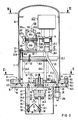
- FIGS. 3 to 7 show the mechanical-electrical embodiment of the ignition sources according to FIGS. 1 and 2.
- a pressure-resistant capsule for the metal housing 9 is formed by a pressure-resistant steel hood 9.1, which has an annular flange 9.2 in the region of the lower hood opening.
- a solid base plate 9.3 which, like parts 9.1 and 9.2, also consists of corrosion-resistant steel, is flanged together in a pressure-tight manner.
- At least one O-ring 14 is inserted between the ring flange 9.2 and the base plate 9.3, which is received by a corresponding ring groove 15 and is flattened under elastic deformation in the illustrated clamped state of the parts 9.2, 9.3.
- the flange screws are designated 16, their head 16.1, their threaded shaft 16.2, one of the associated threaded holes in the base plate 9.3 16.3 and the through holes 9.2 in the ring flange 9.2. Only a flange screw 16 is shown in somewhat more detail; on the opposite side of the flange connection 9.2-9.3, a flange screw 16 is indicated by a center line.
- a temperature-dependent triggering element AE1 is built into the solid base plate 9.3 from the inside.
- This release element is capsule-shaped and is in good heat-conducting contact with the solid base plate 9.3.
- it is a thermocouple in the form of a so-called thermal switch, the two upstanding contact blades of which are designated 17.1 and 17.2.
- the electrical connection between this thermal switch and the gas-tight cast unit 18 of the ignition electronics is made via a plug cable (not shown for simplicity).
- the aforementioned thermal switch combines a temperature sensor and a contact path.
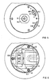
- a second trigger element AE2 (see FIGS. 1 and 2) is the pressure switch AE2, which is clamped to the upper metallic table top 20.1 of a table top arrangement 20 by means of a holding bracket 19 (see also FIG. 4).
- This table top assembly 20 is part of the support device T fastened on the inside of the base plate 9.3, to which the elements of the electrical / electronic circuit of the ignition electronics 18 including a long-term battery arrangement 100 and at least one pressure switch AE2 are fastened.
- the support device T has the already mentioned table top arrangement 20, which is held at a distance from the base plate 9.3 by means of stud bolts 20.3, a lower table top 20.2 consisting of insulating material and carrying the structural unit of the ignition electronics 18 on its underside, the latter being supported by a support plate 20.4 worn, which is screwed to the insulating plate 20.2 with the addition of spacers 21, one of the screws is shown at 22.
- the spacer sleeves 20.5 hold the upper table top 20.1 made of metal parallel or plane-parallel to the lower table top 20.2 by the stud bolts 20.3, on the threaded ends of which protrude upward from the upper table top 20.1, retaining nuts 23 are screwed on with the insertion of washers 24 (see also FIG. 6 ).
- the U-shaped retaining bracket 19 for the pressure switch AE2 is fastened to the upper table top 20.1 with retaining screws 25 (FIGS. 4 and 6).
- the pressure measuring line 26 is passed through the solid base plate 9.3 in a pressure-tight manner and is pressure-tightly connected to the pressure switch AE2 via a connection fitting 27.
- This fitting 27 includes a union nut 27.1 with which a (not shown) conical mouthpiece is coupled to a correspondingly conically shaped counter-mouthpiece of the connecting line 27.2 of the pressure switch AE2.
- a corresponding (standardized) coupling point is located outside the base plate 9.3 in the extension of the measuring line 26 and is designated 28.
- connection end 28.2 is fixed to the housing and provided with a polygon for attaching wrenches
- the other connection end with the (not visible) conical connection mouthpiece is again pressure-tightly connected to the connection end 28.2 by means of a union nut 28.1.
- the latter is a little mar zen executed, which is welded to the outside of the base plate 9.3 sealing and surrounds the through hole 29.
- the latter is slightly expanded where the measuring line 26 is inserted with its end 26.a, and this end 26.a is also sealed to the base plate 9.3 (ring welds 30, 31).
- the outwardly projecting line part 26b of the pressure measuring line 26 ends in a pressure measuring head, not shown, where there is a suitable location for the pressure measurement.
- the pressure measuring head can be arranged at a distance of fractions of meters up to several meters away from the housing 9.
- the battery assembly 100 is also attached to the upper table top.
- An angle piece 101 is screwed with its one leg 101a to the upper table top 20.1, and the two holding jaws 102a and 102b are clamped to the upwardly projecting leg 101b by means of the threaded bolt 103 with the insertion of the two battery bodies 100a, 100b.
- the one holding jaw 102b is pushed onto the threaded bolt 103, which is fastened at one end to the leg 101b (see welded-on retaining nut 104) and tightened against the leg 101b by means of a nut and washer 105, 106.
- the second holding jaw 102a is then pushed onto the free end of the threaded bolt 103 and clamped by means of the wing nut 107 and the spring washer 107a.
- the holding jaws 102a, 102b are provided with channel-shaped recesses 108 corresponding to the circumference of the batteries 100a, 100b to be held.
- connection lines from the battery 100 and the pressure switch AE2 to the unit 18 of the ignition electronics are not shown, nor is the connection cable from this ignition electronics 18 to the solid pin 32, which carries the one ignition electrode 6a of the two ignition electrodes 6a, 6b at its outer end .
- the base plate 9.3 is provided, preferably centrally, with a high-voltage bushing HS for the ignition electrode 6a which is at high potential. The latter is opposed by the counter electrode 6b which is at ground potential.
- the striking distance of the two ignition electrodes 6a, 6b can be adjusted and is held on holding bodies 32, 33 at a distance from the base plate 9.3.
- One of these holding bodies is the massive pin 32 already mentioned, which centrally and sealingly penetrates a high-voltage insulator body 34 inserted into the base plate 9.3 and has an adjustable receptacle 32.1 for the pin-shaped or needle-shaped ignition electrode 6a at its free, downwardly projecting end .
- the insulator body 34 has a neck part 34.1 with an O-ring seal 35, which penetrates the central bore 9.31 in the base plate 9.3 in a sealing manner and is braced on the inside of the base plate 9.3 by a nut 34.2 which is also made of mechanically stable insulating material. So-called metal-ceramic connections are available for the passage of the solid pin 32 through the insulator body 34, which are sufficiently temperature-resistant. To increase the creepage distances, the insulator body 34 is provided with steps 34.3 and ribs 34.4. The counter electrode 6b is held at the free end of a stud 33 screwed into the underside of the base plate 9.3 - likewise within an adjustable receptacle 33.1.
- Both adjustable receptacles 32.1, 33.1 each have oblique bores 36, into which the needle-shaped ignition electrodes 6a, 6b are inserted, in such a way that, viewed from their electrode tips opposite each other with the smallest distance a 1 to their other ends, they each incline to the horizontal, with which it is achieved that any condensed water runs off immediately and cannot influence the ignition characteristic given by the striking distance a 1.
- the adjustable receptacles 32.1 and 33.1 include central bores 37 in the ends of the pin 32 and the bolt 33, which intersect with the oblique bores 36.
- Clamping screws 38 are screwed into the central bores from the outside, which likewise have inclined bores (not described in more detail) and in these are penetrated by the pin-shaped ignition electrodes 6a and 6b. If the clamping screws are tightened after threading the ignition electrodes 6a, 6b and after adjusting their spacing, the ignition electrodes are firmly clamped, with lock nuts (not specified in more detail) sitting at the free end, which serve to prevent rotation.
- an electrode protection space 39 directly surrounding the ignition electrodes 6a, 6b is surrounded by a jacket plate 40 below the base plate 9.3 (cf. also FIG. 7).
- this jacket plate 40 can be perforated in a sieve-like manner, so that the gas mixture located in the protective space 39 is an accurate representation of the gas mixture in the containment; in the sector area 40a (FIG. 7), however, a perforation is omitted for reasons of wind protection for the electrical spark igniter 6.
- FIG. 5 shows a top view of the glass tube of a reed contact section 2.3.
- This contact path is also shown in Figures 1 and 2; it embodies the third trigger element AE3.
- This is triggered manually by means of a test magnet, and accordingly the arrows f3 mean the quantity which is analogous to the magnetic force and which closes the reed contact path 2.3 when one approaches the reed contact path from the outside with a test magnet.
- This makes it possible to check the function of the dry cell 1 or 100 and the electronic / electrical circuit of the ignition electronics 18 without opening the pressure-resistant housing 9. Such checks are carried out at regular intervals, for example daily or weekly, and - if the check shows that the state of charge of the battery arrangement 1 or 100 is no longer sufficient - the batteries are replaced. It can also be a rechargeable battery.
Landscapes
- Engineering & Computer Science (AREA)
- General Engineering & Computer Science (AREA)
- Physics & Mathematics (AREA)
- Combustion & Propulsion (AREA)
- High Energy & Nuclear Physics (AREA)
- Chemical & Material Sciences (AREA)
- Plasma & Fusion (AREA)
- Mechanical Engineering (AREA)
- Battery Mounting, Suspending (AREA)
- Spark Plugs (AREA)
- Secondary Cells (AREA)
- Primary Cells (AREA)
- Air Bags (AREA)
- Feeding And Controlling Fuel (AREA)
Applications Claiming Priority (2)
| Application Number | Priority Date | Filing Date | Title |
|---|---|---|---|
| DE3816711 | 1988-05-17 | ||
| DE3816711 | 1988-05-17 |
Publications (2)
| Publication Number | Publication Date |
|---|---|
| EP0342602A1 true EP0342602A1 (fr) | 1989-11-23 |
| EP0342602B1 EP0342602B1 (fr) | 1991-06-19 |
Family
ID=6354507
Family Applications (2)
| Application Number | Title | Priority Date | Filing Date |
|---|---|---|---|
| EP19890108770 Expired - Lifetime EP0342602B1 (fr) | 1988-05-17 | 1989-05-16 | Dispositif pour la combustion contrôlée d'un mélange détonant hydrogène-air dans une installation nucléaire |
| EP89905666A Pending EP0414761A1 (fr) | 1988-05-17 | 1989-05-16 | Dispositif pour la combustion controlee d'un melange hydrogene/air inflammable dans une installation nucleaire |
Family Applications After (1)
| Application Number | Title | Priority Date | Filing Date |
|---|---|---|---|
| EP89905666A Pending EP0414761A1 (fr) | 1988-05-17 | 1989-05-16 | Dispositif pour la combustion controlee d'un melange hydrogene/air inflammable dans une installation nucleaire |
Country Status (9)
| Country | Link |
|---|---|
| US (1) | US5108696A (fr) |
| EP (2) | EP0342602B1 (fr) |
| JP (1) | JPH03504274A (fr) |
| DE (2) | DE8816470U1 (fr) |
| ES (1) | ES2023278B3 (fr) |
| FI (1) | FI106820B (fr) |
| SU (1) | SU1836605A3 (fr) |
| UA (1) | UA18631A1 (fr) |
| WO (1) | WO1989011721A1 (fr) |
Cited By (1)
| Publication number | Priority date | Publication date | Assignee | Title |
|---|---|---|---|---|
| WO2004068504A1 (fr) * | 2003-01-28 | 2004-08-12 | Framatome Anp Gmbh | Systeme de protection notamment destine au circuit primaire d'une centrale atomique, et procede d'utilisation d'une centrale atomique |
Families Citing this family (11)
| Publication number | Priority date | Publication date | Assignee | Title |
|---|---|---|---|---|
| DE3935916C2 (de) * | 1989-10-27 | 1995-01-26 | Siemens Ag | Vorrichtung zum Zünden von Wasserstoff in einem Behälter |
| US5608767A (en) * | 1994-05-09 | 1997-03-04 | General Electric Company | Neutron-activated direct current source |
| US5672928A (en) * | 1994-05-09 | 1997-09-30 | General Electric Company | Stabilized in-vessel direct current source |
| DE19544346C1 (de) * | 1995-11-28 | 1997-04-03 | Siemens Ag | Sicherheitsbehälter eines Kernkraftwerkes |
| DE19722165C1 (de) * | 1997-05-27 | 1998-09-24 | Siemens Ag | Zündsystem zur Rekombination von Wasserstoff in einem Gasgemisch und Sicherheitsbehälter einer kerntechnischen Anlage |
| US6888713B2 (en) | 2000-12-21 | 2005-05-03 | Douglas Wayne Stamps | Device and method to mitigate hydrogen explosions in vacuum furnaces |
| CN104620324B (zh) * | 2012-08-06 | 2017-05-31 | 特拉华空气喷射火箭达因公司 | 用于冷却剂丧失事故后缓解的封闭式火炬系统 |
| CN102878578B (zh) * | 2012-09-25 | 2014-12-03 | 中国船舶重工集团公司第七一八研究所 | 一种核电站用氢气点火器 |
| JP6399775B2 (ja) * | 2014-03-19 | 2018-10-03 | 三菱重工業株式会社 | 点火装置、及び原子力プラント |
| US11237216B1 (en) | 2017-08-15 | 2022-02-01 | Qnovo Inc. | Method of detecting metal plating in intercalation cells |
| RU2698462C1 (ru) * | 2018-11-01 | 2019-08-27 | Акционерное Общество "Атомэнергопроект" | Способ охлаждения расплава активной зоны ядерного реактора и система контроля охлаждения расплава активной зоны ядерного реактора |
Citations (5)
| Publication number | Priority date | Publication date | Assignee | Title |
|---|---|---|---|---|
| DE3004677A1 (de) * | 1980-02-08 | 1981-08-27 | Babcock-Brown Boveri Reaktor Gmbh, 6800 Mannheim | Verfahren und einrichtung zum abbau des im sicherheitsbehaelter einer wassergekuehlten kernreaktoranlage eingeschlossenen wasserstoffs |
| US4425495A (en) * | 1982-12-10 | 1984-01-10 | Morrison-Knudsen Company, Inc. | Ignitor and enclosure structure |
| EP0233564A2 (fr) * | 1986-02-12 | 1987-08-26 | Forschungszentrum Jülich Gmbh | Dispositif pour écarter l'hydrogène |
| DE3705193A1 (de) * | 1987-02-16 | 1988-08-25 | Kiekebusch Rainer | Zuendsystem und verfahren zur zuendung von niedrigen h(pfeil abwaerts)2(pfeil abwaerts)-konzentrationen bei unfaellen in kernkraftwerken |
| EP0289907A1 (fr) * | 1987-05-08 | 1988-11-09 | Siemens Aktiengesellschaft | Dispositif pour la combustion contrôlée d'un mélange détonable air-hydrogène dans le confinement de réacteurs nucléaires refroidis à l'eau |
Family Cites Families (4)
| Publication number | Priority date | Publication date | Assignee | Title |
|---|---|---|---|---|
| US3598699A (en) * | 1969-04-09 | 1971-08-10 | Gen Electric | Nuclear reactor off-gas burner system |
| BE788538A (fr) * | 1971-09-09 | 1973-03-08 | Westinghouse Electric Corp | Appareil de recombinaison de l'hydrogene et de l'oxygene |
| US4381913A (en) * | 1980-10-15 | 1983-05-03 | Craig Laurence B | Combustion heating system |
| DE3816012A1 (de) * | 1987-08-14 | 1989-11-16 | Siemens Ag | Vorrichtung zur rekombination von wasserstoff und sauerstoff |
-
1988
- 1988-05-17 DE DE8816470U patent/DE8816470U1/de not_active Expired
-
1989
- 1989-05-16 JP JP1505466A patent/JPH03504274A/ja active Pending
- 1989-05-16 EP EP19890108770 patent/EP0342602B1/fr not_active Expired - Lifetime
- 1989-05-16 WO PCT/EP1989/000530 patent/WO1989011721A1/fr not_active Ceased
- 1989-05-16 ES ES89108770T patent/ES2023278B3/es not_active Expired - Lifetime
- 1989-05-16 EP EP89905666A patent/EP0414761A1/fr active Pending
- 1989-05-16 DE DE8989108770T patent/DE58900150D1/de not_active Expired - Lifetime
-
1990
- 1990-09-25 FI FI904708A patent/FI106820B/fi active IP Right Grant
- 1990-11-16 SU SU904831567A patent/SU1836605A3/ru active
- 1990-11-16 UA UA4831567A patent/UA18631A1/uk unknown
- 1990-11-19 US US07/615,465 patent/US5108696A/en not_active Expired - Lifetime
Patent Citations (5)
| Publication number | Priority date | Publication date | Assignee | Title |
|---|---|---|---|---|
| DE3004677A1 (de) * | 1980-02-08 | 1981-08-27 | Babcock-Brown Boveri Reaktor Gmbh, 6800 Mannheim | Verfahren und einrichtung zum abbau des im sicherheitsbehaelter einer wassergekuehlten kernreaktoranlage eingeschlossenen wasserstoffs |
| US4425495A (en) * | 1982-12-10 | 1984-01-10 | Morrison-Knudsen Company, Inc. | Ignitor and enclosure structure |
| EP0233564A2 (fr) * | 1986-02-12 | 1987-08-26 | Forschungszentrum Jülich Gmbh | Dispositif pour écarter l'hydrogène |
| DE3705193A1 (de) * | 1987-02-16 | 1988-08-25 | Kiekebusch Rainer | Zuendsystem und verfahren zur zuendung von niedrigen h(pfeil abwaerts)2(pfeil abwaerts)-konzentrationen bei unfaellen in kernkraftwerken |
| EP0289907A1 (fr) * | 1987-05-08 | 1988-11-09 | Siemens Aktiengesellschaft | Dispositif pour la combustion contrôlée d'un mélange détonable air-hydrogène dans le confinement de réacteurs nucléaires refroidis à l'eau |
Cited By (1)
| Publication number | Priority date | Publication date | Assignee | Title |
|---|---|---|---|---|
| WO2004068504A1 (fr) * | 2003-01-28 | 2004-08-12 | Framatome Anp Gmbh | Systeme de protection notamment destine au circuit primaire d'une centrale atomique, et procede d'utilisation d'une centrale atomique |
Also Published As
| Publication number | Publication date |
|---|---|
| EP0342602B1 (fr) | 1991-06-19 |
| WO1989011721A1 (fr) | 1989-11-30 |
| FI904708A0 (fi) | 1990-09-25 |
| SU1836605A3 (en) | 1993-08-23 |
| FI106820B (fi) | 2001-04-12 |
| US5108696A (en) | 1992-04-28 |
| DE8816470U1 (de) | 1989-09-07 |
| UA18631A1 (uk) | 1997-12-25 |
| EP0414761A1 (fr) | 1991-03-06 |
| ES2023278B3 (es) | 1992-01-01 |
| JPH03504274A (ja) | 1991-09-19 |
| DE58900150D1 (de) | 1991-07-25 |
Similar Documents
| Publication | Publication Date | Title |
|---|---|---|
| EP0342602B1 (fr) | Dispositif pour la combustion contrôlée d'un mélange détonant hydrogène-air dans une installation nucléaire | |
| CH638636A5 (de) | Gasmelder zum einsatz in explosionsgefaehrdeter umgebung. | |
| DE10049071A1 (de) | Sicherungsvorrichtung für einen Stromkreis insbesondere in Kraftfahrzeugen | |
| DE2023624A1 (de) | Sicherheitsschranke zur Eigensicherung | |
| DE19746566A1 (de) | Kurzschließer, insbesondere für eine Störlichtbogen-Schutzvorrichtung zur Verwendung in Anlagen zur Verteilung elektrischer Energie | |
| DE4430284A1 (de) | Einrichtung für Kraftfahrzeuge zur unfallbedingten Trennung einer elektrischen Energiequelle von einem Bordnetz | |
| EP1052665B1 (fr) | Court-circuiteur | |
| DE19916327A1 (de) | Kurzschließer | |
| DE102007033183B4 (de) | Verpolschutzeinrichtung und Verfahren zum Unterbrechen eines Stromes | |
| EP0289907B1 (fr) | Dispositif pour la combustion contrôlée d'un mélange détonable air-hydrogène dans le confinement de réacteurs nucléaires refroidis à l'eau | |
| DE19822780A1 (de) | Verfahren und Vorrichtung zur Überprüfung eines elektrischen Schaltkreises, insbesondere eines Zündschaltkreises eines Kraftfahrzeug-Insassenschutzsystems | |
| DE19746815A1 (de) | Kurzschließer, insbesondere für eine Störlichtbogen-Schutzvorrichtung zur Verwendung in Anlagen zur Verteilung elektrischer Energie | |
| DE8136957U1 (de) | Vorrichtung zum Anzeigen von Schäden oder Störungen in für den privaten Gebrauch bestimmten elektrischen Anlagen | |
| EP0639844B1 (fr) | Dispositif pour disconnexion électrique | |
| DE9401486U1 (de) | Vorrichtung zur elektrischen Trennung | |
| EP0255146B1 (fr) | Procédé et appareil pour tester des filtres dans un milieu explosible | |
| DE69301252T2 (de) | Zündungs- und Heizungsvorrichtung | |
| EP1045415B1 (fr) | Court-circuiteur | |
| DE2046495C3 (de) | Druckgasbehälter zum Aufblasen von Aufprallschutzkissen | |
| DE9400903U1 (de) | Spannungsprüfungseinrichtung | |
| WO1989012897A1 (fr) | Procede et dispositif pour evacuer un melange gazeux inflammable d'une enceinte | |
| DE19746809A1 (de) | Kurzschließer, insbesondere für eine Störlichtbogen-Schutzvorrichtung in Anlagen zur Verteilung elektrischer Energie | |
| DE19544346C1 (de) | Sicherheitsbehälter eines Kernkraftwerkes | |
| DE102011009099B4 (de) | Übertemperatursicherung für eine elektrische Anlage und elektrische Anlagen mit einer Übertemperatursicherung | |
| DE3935916C2 (de) | Vorrichtung zum Zünden von Wasserstoff in einem Behälter |
Legal Events
| Date | Code | Title | Description |
|---|---|---|---|
| PUAI | Public reference made under article 153(3) epc to a published international application that has entered the european phase |
Free format text: ORIGINAL CODE: 0009012 |
|
| AK | Designated contracting states |
Kind code of ref document: A1 Designated state(s): ES |
|
| 17P | Request for examination filed |
Effective date: 19891219 |
|
| 17Q | First examination report despatched |
Effective date: 19900508 |
|
| GRAA | (expected) grant |
Free format text: ORIGINAL CODE: 0009210 |
|
| PUAB | Information related to the publication of an a document modified or deleted |
Free format text: ORIGINAL CODE: 0009199EPPU |
|
| PUAC | Information related to the publication of a b1 document modified or deleted |
Free format text: ORIGINAL CODE: 0009299EPPU |
|
| AK | Designated contracting states |
Kind code of ref document: B1 Designated state(s): ES |
|
| DB1 | Publication of patent cancelled | ||
| RA1 | Application published (corrected) |
Date of ref document: 19891123 Kind code of ref document: A1 |
|
| GRAA | (expected) grant |
Free format text: ORIGINAL CODE: 0009210 |
|
| RBV | Designated contracting states (corrected) |
Designated state(s): BE CH DE ES FR GB IT LI NL SE |
|
| XX | Miscellaneous (additional remarks) |
Free format text: VERBUNDEN MIT 89905666.7/0414761 (EUROPAEISCHE ANMELDENUMMER/VEROEFFENTLICHUNGSNUMMER) DURCH ENTSCHEIDUNG VOM 25.03.91. |
|
| AK | Designated contracting states |
Kind code of ref document: B1 Designated state(s): BE CH DE ES FR GB IT LI NL SE |
|
| XX | Miscellaneous (additional remarks) |
Free format text: VERBUNDEN MIT 89905666.7/0414761 (EUROPAEISCHE ANMELDENUMMER/VEROEFFENTLICHUNGSNUMMER) DURCH ENTSCHEIDUNG VOM 25.03.91. |
|
| REF | Corresponds to: |
Ref document number: 58900150 Country of ref document: DE Date of ref document: 19910725 |
|
| ITF | It: translation for a ep patent filed | ||
| ET | Fr: translation filed | ||
| GBT | Gb: translation of ep patent filed (gb section 77(6)(a)/1977) | ||
| REG | Reference to a national code |
Ref country code: ES Ref legal event code: FG2A Ref document number: 2023278 Country of ref document: ES Kind code of ref document: B3 |
|
| PLBE | No opposition filed within time limit |
Free format text: ORIGINAL CODE: 0009261 |
|
| STAA | Information on the status of an ep patent application or granted ep patent |
Free format text: STATUS: NO OPPOSITION FILED WITHIN TIME LIMIT |
|
| 26N | No opposition filed | ||
| PGFP | Annual fee paid to national office [announced via postgrant information from national office to epo] |
Ref country code: SE Payment date: 19930512 Year of fee payment: 5 Ref country code: BE Payment date: 19930512 Year of fee payment: 5 |
|
| PGFP | Annual fee paid to national office [announced via postgrant information from national office to epo] |
Ref country code: FR Payment date: 19930519 Year of fee payment: 5 |
|
| PGFP | Annual fee paid to national office [announced via postgrant information from national office to epo] |
Ref country code: NL Payment date: 19930531 Year of fee payment: 5 |
|
| PGFP | Annual fee paid to national office [announced via postgrant information from national office to epo] |
Ref country code: CH Payment date: 19931008 Year of fee payment: 5 |
|
| PGFP | Annual fee paid to national office [announced via postgrant information from national office to epo] |
Ref country code: GB Payment date: 19940418 Year of fee payment: 6 |
|
| PGFP | Annual fee paid to national office [announced via postgrant information from national office to epo] |
Ref country code: ES Payment date: 19940512 Year of fee payment: 6 |
|
| PG25 | Lapsed in a contracting state [announced via postgrant information from national office to epo] |
Ref country code: SE Effective date: 19940517 |
|
| PG25 | Lapsed in a contracting state [announced via postgrant information from national office to epo] |
Ref country code: LI Effective date: 19940531 Ref country code: CH Effective date: 19940531 Ref country code: BE Effective date: 19940531 |
|
| BERE | Be: lapsed |
Owner name: SIEMENS A.G. Effective date: 19940531 |
|
| PG25 | Lapsed in a contracting state [announced via postgrant information from national office to epo] |
Ref country code: NL Effective date: 19941201 |
|
| NLV4 | Nl: lapsed or anulled due to non-payment of the annual fee | ||
| EUG | Se: european patent has lapsed |
Ref document number: 89108770.2 Effective date: 19941210 |
|
| PG25 | Lapsed in a contracting state [announced via postgrant information from national office to epo] |
Ref country code: FR Effective date: 19950131 |
|
| REG | Reference to a national code |
Ref country code: CH Ref legal event code: PL |
|
| EUG | Se: european patent has lapsed |
Ref document number: 89108770.2 |
|
| REG | Reference to a national code |
Ref country code: FR Ref legal event code: ST |
|
| PG25 | Lapsed in a contracting state [announced via postgrant information from national office to epo] |
Ref country code: GB Effective date: 19950516 |
|
| PG25 | Lapsed in a contracting state [announced via postgrant information from national office to epo] |
Ref country code: ES Free format text: LAPSE BECAUSE OF NON-PAYMENT OF DUE FEES Effective date: 19950517 |
|
| GBPC | Gb: european patent ceased through non-payment of renewal fee |
Effective date: 19950516 |
|
| REG | Reference to a national code |
Ref country code: ES Ref legal event code: FD2A Effective date: 19990405 |
|
| PG25 | Lapsed in a contracting state [announced via postgrant information from national office to epo] |
Ref country code: IT Free format text: LAPSE BECAUSE OF NON-PAYMENT OF DUE FEES Effective date: 20050516 |
|
| PGFP | Annual fee paid to national office [announced via postgrant information from national office to epo] |
Ref country code: DE Payment date: 20070529 Year of fee payment: 19 |
|
| PG25 | Lapsed in a contracting state [announced via postgrant information from national office to epo] |
Ref country code: DE Free format text: LAPSE BECAUSE OF NON-PAYMENT OF DUE FEES Effective date: 20081202 |