EP0289983A2 - CNC-dispositif flexible de mesure à plusieurs points - Google Patents
CNC-dispositif flexible de mesure à plusieurs points Download PDFInfo
- Publication number
- EP0289983A2 EP0289983A2 EP88107045A EP88107045A EP0289983A2 EP 0289983 A2 EP0289983 A2 EP 0289983A2 EP 88107045 A EP88107045 A EP 88107045A EP 88107045 A EP88107045 A EP 88107045A EP 0289983 A2 EP0289983 A2 EP 0289983A2
- Authority
- EP
- European Patent Office
- Prior art keywords
- measuring
- measuring device
- point
- technology
- devices
- Prior art date
- Legal status (The legal status is an assumption and is not a legal conclusion. Google has not performed a legal analysis and makes no representation as to the accuracy of the status listed.)
- Granted
Links
- 238000005516 engineering process Methods 0.000 claims abstract description 39
- 238000005259 measurement Methods 0.000 claims abstract description 27
- 239000000523 sample Substances 0.000 claims abstract description 21
- 238000012360 testing method Methods 0.000 claims abstract description 17
- 238000011156 evaluation Methods 0.000 claims abstract description 13
- 238000000034 method Methods 0.000 claims description 6
- 238000003860 storage Methods 0.000 claims description 6
- 238000009434 installation Methods 0.000 claims description 5
- 230000002093 peripheral effect Effects 0.000 claims description 5
- 230000006978 adaptation Effects 0.000 claims description 3
- 238000013461 design Methods 0.000 claims description 3
- 238000004439 roughness measurement Methods 0.000 claims 1
- 238000004519 manufacturing process Methods 0.000 description 24
- 238000010586 diagram Methods 0.000 description 4
- 238000011161 development Methods 0.000 description 3
- 230000018109 developmental process Effects 0.000 description 3
- 238000007689 inspection Methods 0.000 description 3
- 238000012937 correction Methods 0.000 description 2
- 230000008878 coupling Effects 0.000 description 2
- 238000010168 coupling process Methods 0.000 description 2
- 238000005859 coupling reaction Methods 0.000 description 2
- 230000010354 integration Effects 0.000 description 2
- 238000003908 quality control method Methods 0.000 description 2
- 230000001133 acceleration Effects 0.000 description 1
- 230000000712 assembly Effects 0.000 description 1
- 238000000429 assembly Methods 0.000 description 1
- 230000015572 biosynthetic process Effects 0.000 description 1
- 238000004364 calculation method Methods 0.000 description 1
- 238000010276 construction Methods 0.000 description 1
- 238000010924 continuous production Methods 0.000 description 1
- 230000008094 contradictory effect Effects 0.000 description 1
- 230000008030 elimination Effects 0.000 description 1
- 238000003379 elimination reaction Methods 0.000 description 1
- 230000007613 environmental effect Effects 0.000 description 1
- 230000002349 favourable effect Effects 0.000 description 1
- 230000006870 function Effects 0.000 description 1
- 230000002452 interceptive effect Effects 0.000 description 1
- 230000003287 optical effect Effects 0.000 description 1
- 230000008439 repair process Effects 0.000 description 1
- 238000004441 surface measurement Methods 0.000 description 1
- 238000003786 synthesis reaction Methods 0.000 description 1
- 238000012549 training Methods 0.000 description 1
Images


Classifications
-
- G—PHYSICS
- G01—MEASURING; TESTING
- G01B—MEASURING LENGTH, THICKNESS OR SIMILAR LINEAR DIMENSIONS; MEASURING ANGLES; MEASURING AREAS; MEASURING IRREGULARITIES OF SURFACES OR CONTOURS
- G01B5/00—Measuring arrangements characterised by the use of mechanical techniques
- G01B5/004—Measuring arrangements characterised by the use of mechanical techniques for measuring coordinates of points
- G01B5/008—Measuring arrangements characterised by the use of mechanical techniques for measuring coordinates of points using coordinate measuring machines
-
- G—PHYSICS
- G01—MEASURING; TESTING
- G01B—MEASURING LENGTH, THICKNESS OR SIMILAR LINEAR DIMENSIONS; MEASURING ANGLES; MEASURING AREAS; MEASURING IRREGULARITIES OF SURFACES OR CONTOURS
- G01B21/00—Measuring arrangements or details thereof, where the measuring technique is not covered by the other groups of this subclass, unspecified or not relevant
- G01B21/02—Measuring arrangements or details thereof, where the measuring technique is not covered by the other groups of this subclass, unspecified or not relevant for measuring length, width, or thickness
- G01B21/04—Measuring arrangements or details thereof, where the measuring technique is not covered by the other groups of this subclass, unspecified or not relevant for measuring length, width, or thickness by measuring coordinates of points
Definitions
- the invention relates to a flexible CNC multi-point measuring device, which represents a combination of components from coordinate measuring technology with elements of multi-point measuring technology and form testing technology, which can be linked together in a common measuring device.
- Such CNC multi-point measuring devices are particularly suitable for integration into a manufacturing process.
- the production measurement technology is subject to constantly higher demands, which result from the use of new manufacturing processes and flexible manufacturing systems, the changed manufacturing structures and manufacturing processes and the extensive automation through the use of new information technologies.
- the design requirements for the micro and macro shape of workpieces must also be taken into account.
- One of the most important tasks of production measurement technology is the recording of geometric features of workpieces (the workpiece shape test). Within this area, several criteria are always decisive for the applicability of production measuring devices for certain measuring tasks.
- the inventive features offer the advantages that, by combining components from coordinate measuring technology with elements of multi-point measuring technology and form testing technology, a link between these contradictory measuring philosophies is carried out in one device and thus the existing measuring gap between the Coordinate measuring technology as a flexible method for the universal total inspection of all measuring tasks specified on any work piece and the multi-point measuring technology as a reliable method for the quick return of selected and production-relevant workpiece characteristics can be concluded.
- This synthesis ensures a high level of measurement accuracy for absolute measurements as well as speed and reproducibility when testing certain design features.
- the starting point for the conception of this production measuring system can be formed on the one hand by the basic principle of coordinate measuring technology and on the other hand by the basic principle of the known multi-point measuring technology.
- elements of multi-point measuring technology for example multiple probes and automated test gauges preset in relation to drawing data, are integrated.
- the measured value acquisition and the measured value evaluation can be carried out by appropriate expansion of the measuring software taken over from the coordinate measuring technique, both in the usual coordinate measuring technique and according to the type of multi-point measuring technique by direct target-actual comparison of certain measuring probe positions. This means that the probes are preset or calibrated on a selected workpiece based on the data specified in the drawing.
- the measuring probes set in this way now move to the measuring points for all other workpieces at high speed and reproducibly determine the measuring data in a target / actual comparison
- the essential properties and advantages of this new multi-point measuring device are the five mutually independent measuring devices, which essentially consist of a bridge with a vertical quill and four horizontal brackets, each with a horizontal quill. Each travel axis is equipped with its own length measuring system to increase accuracy and a compensation device for the inertial forces that occur during acceleration.
- the multi-point measuring device can be manufactured with the measuring range usually required, for example 1000 mm x 1000 mm x 1200 mm.
- the mutually independent measuring devices are modules, by which three-axis measuring units are understood as complete structural units.
- a module designed as a coordinate measuring machine is to be used as a flexible setting master for the other modules used in multi-point measuring technology, as a result of which an embodied setting master is not required.
- a common calibration of all measuring devices can be carried out on a centrally arranged test specimen with an envelope measurement. Furthermore, a common determination of the reference point, namely the zero point of the reference coordinate system, is possible by measurement on a centrally mounted retractable sphere normal.
- the use of several independent measuring systems enables a high measuring point rate with simultaneous workpiece probing from five different directions.
- the measuring device can be assembled from standardized modules and adapted to the respective requirements with little effort, thereby achieving flexibility with regard to the arrangement and size of the measuring axes.
- the module structure allows for a relatively quick repair by simply replacing the module.
- the entire system can be used in connection with the rotary table as a kind of rotary measuring device.
- the main features of the multi-point measuring device can be named as follows: - high flexibility in configuration - Flexibility of a selected configuration limited to a workpiece part family - Various possible combinations between coordinate and multi-position measurement applications - Elimination of a setting master for calibration in multi-point measurement applications - Complete automation of all device functions - Modular structure thanks to standardized assemblies - full integration into the production flow - Information technology chaining in the CAD / CAM / CAQ data network - High reliability and short measuring times as well as quick return of quality data to the production - Production-oriented test statements for quality control within the production island - good reproducibility - High absolute accuracy of the coordinate measuring technology applications - Use of any touch probe and - Large measuring range of approximately 1000 mm x 1000 mm x 1200 mm.
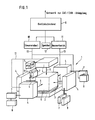
- the measuring devices 1 consists of a centrally arranged measuring table 2, which in the example shown houses an integrated rotary table 3, and the measuring devices 4 arranged around the central measuring table 2 from five sides.
- the measuring devices can be components in any selection from coordinate measuring technology as well as elements of multi-point measuring technology and shape testing technology.
- the measuring devices 4, which operate independently of one another, are arranged both laterally and above the centrally arranged workpiece 5 and have simple measuring probes 6 directed towards the workpiece 5.
- the combination with the integrated rotary table 3 allows the present measuring tasks to be divided into different measuring devices 4, which are specialized in certain measuring tasks and are arranged on the side of the workpiece.
- These measuring devices can consist of the device for determining the workpiece position, the device for checking the position, the device for checking the shape and the device for measuring the roughness.
- the measuring devices 4 are equipped with changing devices 7 for the probe 6 and the measuring heads for all measuring axes. Magazines 8 for the provision of the measuring probes and measuring heads are connected to these changing devices 7.
- This multi-point measuring device 1 is assigned a device control computer 9, which is formed from a control unit 10, an evaluation unit 11 and a memory 12.
- the measuring devices are electrically connected to the device control computer 9 via corresponding lines 13.
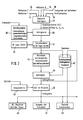
- the device control computer 9 is connected to the integrated control unit 10 and evaluation unit 11 and the mass storage device 12 to a network 14 for CAD / CAM coupling via a corresponding computer coupling interface 15.
- the device control computer 9 is also still connected via bus lines 13 to both the measuring device interface 16 and the peripheral interface 17.
- the measuring device bus line 18 connects to the measuring device interface 16, the control panel 19, the control for drives 20 with the drives 21, the adaptation 22 for the measuring systems 23, the adaptation 24 for the limit switch 25 and the control for additional devices 26 with the additional devices 27 .
- a peripheral bus line 28 can connect a terminal 29, a printer 30, a plotter 31 and a graphics tablet 32 to the peripheral interface 17.
- the mass storage interface 12 establishes the connection to the actual mass storage 33 for the control and evaluation software, for the CNC control program and for the target data.
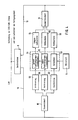
- FIG. 3 shows the flowchart for evaluating measuring points with the evaluation software, which is essentially known from coordinate measuring technology.
- the measuring axes 34, the touch probe and the transducers 36 and the rotary table axis 36 are combined, adapted and superimposed in block 37.
- the determined point coordinates X, Y and Z as well as the corresponding probing directions for X, Y and Z are forwarded and corrected on the basis of temperature correction data 38 in block 39.
- the coordinate and probing directions corrected in this way are transformed into the tool position system 14.
- the point coordinates, measurement results and trend data are stored in a parallel memory 42, while the transformed point coordinates and probing directions are also fed into the system 43 in parallel with the calculation of compensation form elements and the measurement uncertainty.
- the link is then made with the output of the measurement result, which is stored in the memory 42.
- the target / actual comparison 46 takes place, the test result of which is passed on to the output module 47 of the protocol, to the NC machine and CAD / CAM level 48 and to the statistics module 49.
- the trend data from the memory 42 are also introduced into the statistics module.
- the block diagram according to FIG. 4 shows the cantilever and bridge assembly in connection to the device control computer 9.
- the control unit 10 uses blocks 50 to actuate the major axes 51, the touch probes 52 and the transducers 53 once.
- the sensors 53 are functionally connected to the workpiece 5.
- the values determined from the major axes are fed to the evaluation unit 11 via a length measuring system 54, while corresponding measuring systems 55 also feed the determined values from the touch probes and from the sensor to the evaluation unit 11.
- the evaluation results are made available by the evaluation unit 11 via the line 13 to the device control computer 9 and processed there.
- Laser interferometers or optical length measuring systems can be used as length measuring systems.
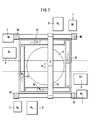
- the structure of the measuring device of the multi-point measuring device 1 can be made in a simple construction in such a way that four columns 56 are arranged at a uniform distance from one another in a square.
- the measuring table 57 with the measuring surface 58 and the measuring area 59 is located centrally between the four columns 56.
- the base frame is designated by 60.
- an installation space 61 is provided for horizontal brackets 62, while a further free space 63 is provided between the pillars 56 in order to be able to load the multi-point measuring device with workpieces, for example, and to achieve improved accessibility.
- the free space 63 is also necessary so that the cantilever arms of the measuring device can be moved without problems.
- the installation space 64 for the bridge 65 is located above the pillars 56.
- the measuring table 2 is designed as a rotary table 3 with an angle measuring device.
- FIG. 8 shows a kinematic model of the multi-point measuring device 1 which is shown in FIG. 9 as a device unit.
- the multi-point measuring device consists of a total of eleven horizontal travel axes 66, to which the bridge 65 also belongs.
- the eleven horizontal traversing axes 66 and 65 allow the probe 6 to be moved in both the X and Y directions.
- the vertical traversing axes 67 offer the possibility that the probe 6 can be moved in the Z direction. The same direction of movement in the Z coordinate takes place through the vertical sleeve 68.
- the four horizontal arms 62 in turn provide movements of the probe 6 in the two coordinate directions X and Y.
- each probe 6 can be moved in the three coordinate directions X, Y and Z independently of the other probes 67.
- the respective travel axes 66 and 67 are designed in the form of rails which are connected to the corner columns 56.
- a vertical travel axis 67 forms a vertical connection between two end-side travel rails 66.
- the measuring device 4 can be moved vertically on this vertical connection rail 67 and each has a horizontal arm 62 in the form of a quill which receives the measuring buttons 6.
- the measuring buttons can be designed as single or as multiple buttons.
- the bridge 65 is guided on the upper traversing axes in rails 66 which rest on the columns 56.
- the measuring device 4 can be moved in the Y direction on the bridge 65 and also has the vertical sleeve 68 with the measuring probe 6.
- the measuring table 2 has the integrated turntable 3 with an angle measuring device and is also movable in the coordinate directions X and Y.
Landscapes
- Physics & Mathematics (AREA)
- General Physics & Mathematics (AREA)
- Length Measuring Devices With Unspecified Measuring Means (AREA)
- A Measuring Device Byusing Mechanical Method (AREA)
- Length Measuring Devices By Optical Means (AREA)
Applications Claiming Priority (2)
| Application Number | Priority Date | Filing Date | Title |
|---|---|---|---|
| DE3714862 | 1987-05-05 | ||
| DE19873714862 DE3714862A1 (de) | 1987-05-05 | 1987-05-05 | Flexible cnc-vielstellenmesseinrichtung |
Publications (3)
| Publication Number | Publication Date |
|---|---|
| EP0289983A2 true EP0289983A2 (fr) | 1988-11-09 |
| EP0289983A3 EP0289983A3 (en) | 1990-06-20 |
| EP0289983B1 EP0289983B1 (fr) | 1992-11-11 |
Family
ID=6326838
Family Applications (1)
| Application Number | Title | Priority Date | Filing Date |
|---|---|---|---|
| EP88107045A Expired - Lifetime EP0289983B1 (fr) | 1987-05-05 | 1988-05-03 | CNC-dispositif flexible de mesure à plusieurs points |
Country Status (4)
| Country | Link |
|---|---|
| US (1) | US4953306A (fr) |
| EP (1) | EP0289983B1 (fr) |
| JP (1) | JPS63285407A (fr) |
| DE (2) | DE3714862A1 (fr) |
Cited By (5)
| Publication number | Priority date | Publication date | Assignee | Title |
|---|---|---|---|---|
| DE3836540A1 (de) * | 1988-10-27 | 1990-05-03 | Lemmerz Werke Kgaa | Mehrstellenmesseinrichtung zur vermessung von kraftfahrzeugraedern, deren felgen und/oder radschuesseln |
| EP0417677A1 (fr) * | 1989-09-11 | 1991-03-20 | Industrie-Handels-Aktiengesellschaft | Dispositif pour mesurer des distances sur une pièce à usiner avec un pied à coulisse permettant de mesurer numériquement ces distances |
| CH678890A5 (en) * | 1989-09-11 | 1991-11-15 | Inhag Ind Handels Ag | Measuring arrangement for distances on workpiece |
| WO1993014367A3 (fr) * | 1992-01-08 | 1993-09-30 | Rank Taylor Hobson Ltd | Appareil metrologique |
| EP0802393A3 (fr) * | 1996-04-15 | 1998-04-15 | Carl Zeiss | Dispositif de mesure pour arpenter des pièces à usiner |
Families Citing this family (29)
| Publication number | Priority date | Publication date | Assignee | Title |
|---|---|---|---|---|
| GB2202659B (en) * | 1987-02-23 | 1991-07-17 | Mitutoyo Corp | Coordinate measuring instrument and method of generating pattern data concerning shape of work to be measured |
| DE3941144C2 (de) * | 1989-12-13 | 1994-01-13 | Zeiss Carl Fa | Koordinatenmeßgerät zur berührungslosen Vermessung eines Objekts |
| US5165296A (en) * | 1990-01-12 | 1992-11-24 | Ken Yanagisawa | Drive system |
| DE4022672A1 (de) * | 1990-07-17 | 1992-01-23 | Inst Produktionstechnik Karlsr | Mehrstellenmessgeraet |
| US5251156A (en) * | 1990-08-25 | 1993-10-05 | Carl-Zeiss-Stiftung, Heidenheim/Brenz | Method and apparatus for non-contact measurement of object surfaces |
| SE468727B (sv) * | 1991-07-09 | 1993-03-08 | Johansson Ab C E | Maskinstativ, saerskilt foer s k koordinatmaetmaskiner, jaemte saett att utfoera maskinstativet |
| GB9120029D0 (en) * | 1991-09-19 | 1991-11-06 | System E Controls Ltd | Measuring apparatus and method |
| US5314397A (en) * | 1992-07-31 | 1994-05-24 | Ford Motor Company | Positioning apparatus for multiple-spindle machining |
| US5477618A (en) * | 1994-05-03 | 1995-12-26 | Gibson; Stephen P. | Sand core dimension checking apparatus |
| KR0141161B1 (ko) * | 1995-03-20 | 1998-07-01 | 이대원 | 회전 테이블을 구비한 스테이지 장치 및 스테이지 장치의 구동 방법 |
| IT1280989B1 (it) * | 1995-10-20 | 1998-02-11 | Dea Spa | Calibro per il collaudo dimensionale di pezzi. |
| US5881470A (en) * | 1996-08-21 | 1999-03-16 | Nearfield Systems Incorporated | Vertical tower for a two-axis measurement system |
| US5806199A (en) * | 1996-11-26 | 1998-09-15 | Everett Pattern & Manufacturing Inc. | Three-dimensional part measurement system |
| CA2254851A1 (fr) * | 1997-03-11 | 1998-09-17 | Werner Haug | Dispositif de mesure de volume |
| KR100355558B1 (ko) * | 1997-06-16 | 2002-12-26 | 한국전기초자 주식회사 | 음극선관용펀넬결합체의검사장치및검사방법 |
| US6115925A (en) * | 1998-05-01 | 2000-09-12 | Powerchip Semiconductor Corp. | Probepin-adjusting jig |
| FI108337B (fi) * | 1998-05-20 | 2002-01-15 | Autorobot Finland | Mittauslaitteisto ja menetelmõ autonkorin oikaisuty÷ssõ autonkorin mittauksessa |
| US6470587B1 (en) | 1999-07-09 | 2002-10-29 | Vought Aircraft Industries, Inc. | Method and system for part measurement and verification |
| US6473987B1 (en) * | 1999-12-28 | 2002-11-05 | Accretech Usa, Inc. | Method for measuring wafer thickness |
| DE10136388A1 (de) * | 2001-07-26 | 2003-02-13 | Zeiss Carl | System zum Vermessen eines optischen Systems, insbesondere eines Objektives |
| US6742273B2 (en) * | 2002-08-30 | 2004-06-01 | Tokyo Seimitsu Co., Ltd. | Workpiece measuring apparatus |
| JP4840144B2 (ja) * | 2005-01-19 | 2011-12-21 | 三菱電機株式会社 | 位置決め装置及び位置決め方法 |
| CN1924519B (zh) * | 2005-09-02 | 2011-11-30 | 鸿富锦精密工业(深圳)有限公司 | 多点量测系统及方法 |
| JP6113998B2 (ja) * | 2012-10-18 | 2017-04-12 | 株式会社ミツトヨ | 形状測定機、形状測定機の調整方法および形状測定方法 |
| CN103344161A (zh) * | 2013-07-02 | 2013-10-09 | 景鑫精密组件(昆山)有限公司 | 快速量测治具 |
| WO2015147910A1 (fr) * | 2014-03-24 | 2015-10-01 | Marposs Corporation | Appareil d'inspection d'alésages usinés |
| US9581424B2 (en) * | 2014-12-09 | 2017-02-28 | Tokyo Seimitsu Co., Ltd. | Roundness measuring apparatus |
| JP6530974B2 (ja) * | 2015-06-10 | 2019-06-12 | 株式会社ミツトヨ | 測定機の衝突防止装置 |
| DE102017207841A1 (de) * | 2017-05-10 | 2018-11-15 | Robert Bosch Gmbh | Vorrichtung zum Erfassen einer Schichtdicke eines beschichteten Bauteils, Verfahren |
Family Cites Families (9)
| Publication number | Priority date | Publication date | Assignee | Title |
|---|---|---|---|---|
| CH447626A (fr) * | 1966-08-10 | 1967-11-30 | Vitale Pasquale | Appareil pour exécuter la perspective centrale d'un objet éloigné, et procédé de mise en action de l'appareil |
| US3499227A (en) * | 1968-05-06 | 1970-03-10 | Caterpillar Tractor Co | Contour recorder |
| US3594909A (en) * | 1969-02-26 | 1971-07-27 | United States Steel Corp | Apparatus for measuring a dimension of a member |
| US3750295A (en) * | 1971-07-22 | 1973-08-07 | Werkzeugmasch Veb | Measuring machine |
| IT1144709B (it) * | 1981-05-15 | 1986-10-29 | Dea Spa | Sistema di misura dimensionale servito da una pluralita di bracci operativi e controllato da un sistema a calcolatore |
| GB2112140B (en) * | 1981-12-16 | 1985-08-07 | Mauser Werke Oberndorf | Coordinate measuring machine |
| US4631834A (en) * | 1984-04-20 | 1986-12-30 | Mitutuoyo Mfg. Co., Ltd. | Coordinate measuring instrument |
| GB8605325D0 (en) * | 1986-03-04 | 1986-04-09 | Rank Taylor Hobson Ltd | Workpiece position control |
| JPH0647A (ja) * | 1992-04-14 | 1994-01-11 | Ee P S:Kk | 室内空気中の小昆虫の撲滅方法 |
-
1987
- 1987-05-05 DE DE19873714862 patent/DE3714862A1/de active Granted
-
1988
- 1988-04-20 US US07/183,828 patent/US4953306A/en not_active Expired - Fee Related
- 1988-04-21 JP JP63099282A patent/JPS63285407A/ja active Pending
- 1988-05-03 DE DE8888107045T patent/DE3875790D1/de not_active Expired - Fee Related
- 1988-05-03 EP EP88107045A patent/EP0289983B1/fr not_active Expired - Lifetime
Cited By (7)
| Publication number | Priority date | Publication date | Assignee | Title |
|---|---|---|---|---|
| DE3836540A1 (de) * | 1988-10-27 | 1990-05-03 | Lemmerz Werke Kgaa | Mehrstellenmesseinrichtung zur vermessung von kraftfahrzeugraedern, deren felgen und/oder radschuesseln |
| EP0417677A1 (fr) * | 1989-09-11 | 1991-03-20 | Industrie-Handels-Aktiengesellschaft | Dispositif pour mesurer des distances sur une pièce à usiner avec un pied à coulisse permettant de mesurer numériquement ces distances |
| CH678890A5 (en) * | 1989-09-11 | 1991-11-15 | Inhag Ind Handels Ag | Measuring arrangement for distances on workpiece |
| WO1993014367A3 (fr) * | 1992-01-08 | 1993-09-30 | Rank Taylor Hobson Ltd | Appareil metrologique |
| EP0802393A3 (fr) * | 1996-04-15 | 1998-04-15 | Carl Zeiss | Dispositif de mesure pour arpenter des pièces à usiner |
| US5901455A (en) * | 1996-04-15 | 1999-05-11 | Carl-Zeiss-Stiftung Trading As Carl Zeiss | Measuring device for measuring workpieces |
| USRE37695E1 (en) * | 1996-04-15 | 2002-05-14 | Carl-Zeiss-Stiftung | Measuring device for measuring workpieces |
Also Published As
| Publication number | Publication date |
|---|---|
| US4953306A (en) | 1990-09-04 |
| DE3714862C2 (fr) | 1992-04-02 |
| EP0289983B1 (fr) | 1992-11-11 |
| DE3875790D1 (de) | 1992-12-17 |
| DE3714862A1 (de) | 1988-11-17 |
| JPS63285407A (ja) | 1988-11-22 |
| EP0289983A3 (en) | 1990-06-20 |
Similar Documents
| Publication | Publication Date | Title |
|---|---|---|
| EP0289983B1 (fr) | CNC-dispositif flexible de mesure à plusieurs points | |
| DE3784047T2 (de) | Kalibrierungsverfahren für ein Koordinatenmessgerät und ähnliche Geräte. | |
| DE69106222T2 (de) | Vorrichtung zur kontinuierlichen Fehlermessung von Werkstückformen und Messverfahren zur Anwendung der Vorrichtung. | |
| EP1393012B1 (fr) | Procede de determination de proprietes d'un appareil de mesure de coordonnees et objet de test correspondant | |
| EP0638781B1 (fr) | Procédé d'étallonnage pour déterminer et compenser diverses forces de palpage des systèmes de mesures de plusieurs coordonnées | |
| EP2972078B1 (fr) | Méthode de correction de déviation angulaire lors de l'opération d'un appareil de mesure de coordonnées | |
| WO2008141608A2 (fr) | Dispositif et procédé d'étalonnage d'ensembles pivotants, en particulier sur des machines de découpage | |
| DE102020206719A1 (de) | Positionsmessverfahren und Positionsmesssystem für ein Objekt in einer Werkzeugmaschine | |
| DE10339194B4 (de) | Verfahren zur Ermittlung systematischer geometrischer Abweichungen in technischen Mehrkörpersystemen | |
| DE3785645T2 (de) | Pruefung der einstellung eines werkzeugs. | |
| DE102020213847A1 (de) | Korrekturwertmessverfahren und Korrekturwertmesssystem eines Positionsmesssensors in einer Werkzeugmaschine | |
| EP1019669B1 (fr) | Dispositif de detection de la position de deux corps | |
| DE602005005839T3 (de) | Verwendung von oberflächenmesssonden | |
| DE102017126198B4 (de) | Verfahren und System zur lehrenlosen Vermessung eines Gewindes | |
| DE3781674T2 (de) | Positionsbestimmungsverfahren innerhalb des messraumes eines koordinatenmessgeraetes und dergleichen und system dafuer. | |
| DE19921325A1 (de) | Kalibriervorrichtung für einen parallelkinematischen Manipulator | |
| DE60128574T2 (de) | Verfahren zur Kalibrierung eines Messgerätes | |
| DE602005004092T2 (de) | Gerät zum Messen der Oberflächenrauhigkeit oder der Kontur eines Objektes | |
| EP0729005A1 (fr) | Dispositif de mesure avec 6 degrés de liberté | |
| DE69119975T2 (de) | Korrektureinrichtung für Koordinatensysteme bei Werkzeugmaschinen | |
| DE19809589B4 (de) | Verfahren zur Kalibrierung eines Tasters eines Koordinatenmeßgerätes | |
| DE3640287A1 (de) | Verfahren zur erzeugung eines gemeinsamen koordinatensystems bei mehrarmigen koordinatenmessgeraeten | |
| WO1994007187A1 (fr) | Procede permettant de verifier la precision d'une machine a commande numerique | |
| WO1986001885A1 (fr) | Procede et dispositif pour mesurer une piece | |
| DE10328640B4 (de) | Messanordnung zur Prüfung der Arbeitsgenauigkeit einer Maschine |
Legal Events
| Date | Code | Title | Description |
|---|---|---|---|
| PUAI | Public reference made under article 153(3) epc to a published international application that has entered the european phase |
Free format text: ORIGINAL CODE: 0009012 |
|
| AK | Designated contracting states |
Kind code of ref document: A2 Designated state(s): CH DE FR GB IT LI SE |
|
| PUAL | Search report despatched |
Free format text: ORIGINAL CODE: 0009013 |
|
| RHK1 | Main classification (correction) |
Ipc: G01B 21/04 |
|
| AK | Designated contracting states |
Kind code of ref document: A3 Designated state(s): CH DE FR GB IT LI SE |
|
| 17P | Request for examination filed |
Effective date: 19900516 |
|
| 17Q | First examination report despatched |
Effective date: 19910704 |
|
| GRAA | (expected) grant |
Free format text: ORIGINAL CODE: 0009210 |
|
| AK | Designated contracting states |
Kind code of ref document: B1 Designated state(s): CH DE FR GB IT LI SE |
|
| REF | Corresponds to: |
Ref document number: 3875790 Country of ref document: DE Date of ref document: 19921217 |
|
| ITF | It: translation for a ep patent filed | ||
| GBT | Gb: translation of ep patent filed (gb section 77(6)(a)/1977) |
Effective date: 19930128 |
|
| ET | Fr: translation filed | ||
| PGFP | Annual fee paid to national office [announced via postgrant information from national office to epo] |
Ref country code: DE Payment date: 19930717 Year of fee payment: 6 |
|
| PLBE | No opposition filed within time limit |
Free format text: ORIGINAL CODE: 0009261 |
|
| STAA | Information on the status of an ep patent application or granted ep patent |
Free format text: STATUS: NO OPPOSITION FILED WITHIN TIME LIMIT |
|
| 26N | No opposition filed | ||
| PGFP | Annual fee paid to national office [announced via postgrant information from national office to epo] |
Ref country code: FR Payment date: 19940328 Year of fee payment: 7 |
|
| PGFP | Annual fee paid to national office [announced via postgrant information from national office to epo] |
Ref country code: CH Payment date: 19940331 Year of fee payment: 7 |
|
| PGFP | Annual fee paid to national office [announced via postgrant information from national office to epo] |
Ref country code: GB Payment date: 19940425 Year of fee payment: 7 |
|
| PGFP | Annual fee paid to national office [announced via postgrant information from national office to epo] |
Ref country code: SE Payment date: 19940530 Year of fee payment: 7 |
|
| EAL | Se: european patent in force in sweden |
Ref document number: 88107045.2 |
|
| PG25 | Lapsed in a contracting state [announced via postgrant information from national office to epo] |
Ref country code: DE Effective date: 19950201 |
|
| PG25 | Lapsed in a contracting state [announced via postgrant information from national office to epo] |
Ref country code: GB Effective date: 19950503 |
|
| PG25 | Lapsed in a contracting state [announced via postgrant information from national office to epo] |
Ref country code: SE Effective date: 19950504 |
|
| PG25 | Lapsed in a contracting state [announced via postgrant information from national office to epo] |
Ref country code: LI Effective date: 19950531 Ref country code: CH Effective date: 19950531 |
|
| GBPC | Gb: european patent ceased through non-payment of renewal fee |
Effective date: 19950503 |
|
| REG | Reference to a national code |
Ref country code: CH Ref legal event code: PL |
|
| EUG | Se: european patent has lapsed |
Ref document number: 88107045.2 |
|
| PG25 | Lapsed in a contracting state [announced via postgrant information from national office to epo] |
Ref country code: FR Effective date: 19960229 |
|
| REG | Reference to a national code |
Ref country code: FR Ref legal event code: ST |
|
| REG | Reference to a national code |
Ref country code: FR Ref legal event code: ST |
|
| PG25 | Lapsed in a contracting state [announced via postgrant information from national office to epo] |
Ref country code: IT Free format text: LAPSE BECAUSE OF NON-PAYMENT OF DUE FEES;WARNING: LAPSES OF ITALIAN PATENTS WITH EFFECTIVE DATE BEFORE 2007 MAY HAVE OCCURRED AT ANY TIME BEFORE 2007. THE CORRECT EFFECTIVE DATE MAY BE DIFFERENT FROM THE ONE RECORDED. Effective date: 20050503 |