EP0291992A2 - Durchflusssteuerung - Google Patents
Durchflusssteuerung Download PDFInfo
- Publication number
- EP0291992A2 EP0291992A2 EP88108068A EP88108068A EP0291992A2 EP 0291992 A2 EP0291992 A2 EP 0291992A2 EP 88108068 A EP88108068 A EP 88108068A EP 88108068 A EP88108068 A EP 88108068A EP 0291992 A2 EP0291992 A2 EP 0291992A2
- Authority
- EP
- European Patent Office
- Prior art keywords
- pressure chamber
- pressure
- oil
- valve
- inflow
- Prior art date
- Legal status (The legal status is an assumption and is not a legal conclusion. Google has not performed a legal analysis and makes no representation as to the accuracy of the status listed.)
- Granted
Links
Images




Classifications
-
- B—PERFORMING OPERATIONS; TRANSPORTING
- B62—LAND VEHICLES FOR TRAVELLING OTHERWISE THAN ON RAILS
- B62D—MOTOR VEHICLES; TRAILERS
- B62D7/00—Steering linkage; Stub axles or their mountings
- B62D7/06—Steering linkage; Stub axles or their mountings for individually-pivoted wheels, e.g. on king-pins
- B62D7/14—Steering linkage; Stub axles or their mountings for individually-pivoted wheels, e.g. on king-pins the pivotal axes being situated in more than one plane transverse to the longitudinal centre line of the vehicle, e.g. all-wheel steering
- B62D7/15—Steering linkage; Stub axles or their mountings for individually-pivoted wheels, e.g. on king-pins the pivotal axes being situated in more than one plane transverse to the longitudinal centre line of the vehicle, e.g. all-wheel steering characterised by means varying the ratio between the steering angles of the steered wheels
- B62D7/1554—Steering linkage; Stub axles or their mountings for individually-pivoted wheels, e.g. on king-pins the pivotal axes being situated in more than one plane transverse to the longitudinal centre line of the vehicle, e.g. all-wheel steering characterised by means varying the ratio between the steering angles of the steered wheels comprising a fluid interconnecting system between the steering control means of the different axles
- B62D7/1563—Steering linkage; Stub axles or their mountings for individually-pivoted wheels, e.g. on king-pins the pivotal axes being situated in more than one plane transverse to the longitudinal centre line of the vehicle, e.g. all-wheel steering characterised by means varying the ratio between the steering angles of the steered wheels comprising a fluid interconnecting system between the steering control means of the different axles provided with fluid control means
-
- Y—GENERAL TAGGING OF NEW TECHNOLOGICAL DEVELOPMENTS; GENERAL TAGGING OF CROSS-SECTIONAL TECHNOLOGIES SPANNING OVER SEVERAL SECTIONS OF THE IPC; TECHNICAL SUBJECTS COVERED BY FORMER USPC CROSS-REFERENCE ART COLLECTIONS [XRACs] AND DIGESTS
- Y10—TECHNICAL SUBJECTS COVERED BY FORMER USPC
- Y10T—TECHNICAL SUBJECTS COVERED BY FORMER US CLASSIFICATION
- Y10T137/00—Fluid handling
- Y10T137/2496—Self-proportioning or correlating systems
- Y10T137/2559—Self-controlled branched flow systems
- Y10T137/2574—Bypass or relief controlled by main line fluid condition
- Y10T137/2579—Flow rate responsive
- Y10T137/2594—Choke
Definitions
- the present invention relates to a flow control apparatus used in a hydraulic system.
- a four-wheel steering system in a vehicle is known as a hydraulic system.
- This system comprises a power steering device for steering front wheels by generating an oil pressure in accordance with turning of a steering wheel, a hydraulic actuator for steering rear wheels, and an oil pump arranged to be driven by, e.g., a rear-wheel differential mechanism and adapted to generate an oil pressure in accordance with a vehicle speed.
- a control valve is arranged in a hydraulic circuit connecting the oil pump to the hydraulic actuator. The control valve is designed so as to switch the hydraulic circuit in accordance with the oil pressure generated by the power steering device.
- the rear wheels can be steered in the same direction as the front wheels by the oil pressure generated by the oil pump while the vehicle is moving at high speed.
- traveling stability of the vehicle during a high-speed traveling mode can be improved.
- the amount of oil delivered from the oil pump is increased with an increase in vehicle speed.
- the generated oil pressure of the oil pump is excessively increased within a vehicle speed range exceeding a certain speed level, thereby steering the rear wheels at an excessive steering angle and degrading durability of the hydraulic circuit.
- a flow control valve is easily used as means for solving such problems.
- the flow control valve serves to return part of working oil to the suction side of the oil pump by opening a return path when the amount of oil delivered from the oil pump exceeds a predetermined value.
- the viscosity of a working oil flowing through hydraulic circuits in hydraulic systems varies depending on the oil temperature, although this problem is not limited only to such a hydraulic four-wheel steering system as described above.
- the viscosity of the working oil is high, whereas when it is high, the viscosity of the working oil becomes low.
- a generated oil pressure is much higher when the oil temperature is low than when the oil temperature is high. That is, the steering angle of the rear wheels, which is determined in accordance with the oil pressure applied to the hydraulic actuator, is changed by the oil temperature, and hence steering characteristic of the rear wheels is changed by the temperature of the working oil.
- the present invention has been made in consideration of the above situation, and has as its object to provide a flow control apparatus for a hydraulic system, which can compensate for a change in a generated oil pressure according to a change in viscosity of the working oil caused by a temperature change thereof.
- a flow control apparatus comprising inflow port means into which a working oil flows, outflow port means from which the working oil flows out, return port means for returning part of the working oil, elongate throttling path means for causing the inflow port means to communicate with the outflow port means, and actuating valve means arranged to be movable in response to the pressure difference between upstream and downstream sides of the throttling path means, for opening and closing of the return port means, thereby opening the return port means when the pressure difference exceeds a predetermined value.
- the flow resistance of the working oil flowing through the throttling path means is greatly changed in accordance with changes in temperature of the working oil, i.e., changes in viscosity. For this reason, the pressure difference between the upstream and downstream of the throttling path means at a constant flow rate decreases with an increase in the oil temperature. Therefore, the flow rate of the working oil required to cause the actuating valve, which is operated in accordance with the pressure difference to open the return port means increases with an increase in the oil temperature.
- an outflow rate is controlled to be decreased by the flow control apparatus. When the oil temperature is high, the outflow rate is controlled to be increased.
- the present invention comprises throttle path control means for shortening an effective length of the throttling path means, in accordance with a displacement of the actuating valve in such a direction wherein the valve opens the return port means.
- the effective length of the throttling path means is shortened by the control means when the return port is opened, a difference in pressure between the upstream and downstream sides of the throttling path means decreases and the actuating valve means moves in a direction closing the return port means.
- the amount of working oil returning from the return port means decreases, and a substantial opening degree of the return port means increases with an increase in the outflow rate. Therefore, the outflow rate can be changed in accordance with changes in the oil temperature, and the outflow rate can be increased with an increase in the inflow rate.
- the oil pressure corresponding to the inflow rate can be generated while the generated oil pressure is stabilized regardless of changes in the oil temperature.
- Fig. 1 shows a four-wheel steering system installed in a vehicle and provided with a flow control apparatus according to a first embodiment of the present invention.
- the vehicle comprises a pair of front wheels 1 and a pair of rear wheels 2.
- Front wheels 1 are steered by steering wheel 3 through power steering device 4.
- Steering wheel 3 is coupled to power cylinder 6 of the power steering device through steering shaft 5 and steering gear box 7.
- the interior of power cylinder 6 is partitioned into left and right chambers 9a and 9b by piston 8.
- Two end portions of piston rod 10 of piston 8 are coupled through tie rods 11 to knuckle arms 12 for supporting front wheels 1.
- Steering gear box 7 is connected to reservoir tank 13 of power steering device 4 and oil pump 14. In this case, oil pump 14 is driven by engine 15.
- Rear suspension 16 of the vehicle is constituted by cross member 17, two pairs of upper and lower lateral arms (upper and lower arms 18a and 18b), and a pair of trailing arms 19.
- Outer end portions of each pair of upper and lower arms 18a and 18b are coupled to corresponding rear-wheel support member 20 for supporting rear wheel 2, and inner end portions of arms 18a and 18b are coupled to the central portion of cross member 17.
- a leading end portion of each trailing arm 19 is coupled to one of the outer end portions of cross member 17, and its trailing end portion is fixed to rear-wheel support member 20.
- Each trailing arm 19 is divided into front and rear arms 21a and 21b. Front and rear arms 21a and 21b are pivotally coupled by substantially vertical pivot shaft 22.
- Elastic member 23 such as rubber is attached between each leading end portion of rear arm 21b and the corresponding trailing end portion of front arm 21a.
- the four-wheel steering system comprises hydraulic actuator 24 for steering the rear wheels, and oil pump (oil pressure source) 26, driven by a gear arranged in rear-wheel differential device 25, for steering the rear wheels.
- Hydraulic actuator 24 is fixed to cross member 20 along the widthwise direction of the vehicle.
- Hydraulic actuator 24 comprises hydraulic cylinder 27.
- the interior of hydraulic cylinder 27 is partitioned into left and right chambers 29a and 29b by piston 28.
- Two end portions of piston rod 30 of piston 28 are coupled to the leading end portions of corresponding rear arms 21b through tie rods 31.
- Control valve 33 is interposed midway along hydraulic circuit 32 for connecting between hydraulic actuator 24 and oil pump 26.
- Control valve 33 is constituted by sleeve 34 and spool 35 arranged therein to be movable in the axial direction.
- Pilot signal pressure chambers 36a and 36b are respectively defined at the left and right end portions of sleeve 34.
- Spring members 37a and 37b are respectively arranged in pilot signal pressure chambers 36a and 36b so as to hold spool at the neutral position.
- Left pilot signal pressure chamber 36a is connected to left chamber 9a of power cylinder 6 through connecting path 38a, whereas right pilot signal pressure chamber 36b is connected to right chamber 9b of power cylinder 6 through connecting path 38b.
- Lands 35a, 35b, and 35c are formed on the outer periphery of spool 35.
- First and second valve chambers 39a and 39b each having a small diameter are respectively defined between lands 35a and 35b, and between lands 35b and 35c.
- First, second, third, fourth, fifth, and sixth ports 40a, 40b, 40c, 40d, 40e, and 40f are formed in sleeve 34. In this case, while spool 35 is held at the neutral position, first, second, and fifth ports 40a, 40b, and 40e of sleeve 34 communicate with first valve chamber 39a of spool 35, and third, fourth, and sixth ports 40c, 40d, and 40f communicate with valve chamber 39b.
- First and fourth ports 40a and 40d are connected to the delivery port of oil pump 26 through oil introducing path 41 of hydraulic circuit 32.
- Second and third ports 40b and 40c are connected to reservoir tank 13 through return path 42.
- fifth port 40e is connected to left chamber 29a of hydraulic cylinder 27 through first oil path 43a of hydraulic circuit 32
- sixth port 40f is connected to left chamber 29b of hydraulic cylinder 27 through second oil path 43b. Note that the suction port of oil pump 26 communicates with reservoir tank 13 through connecting path 44.
- Piston 8 in power cylinder 6 of power steering device 4 is held at the neutral position during straight traveling of the vehicle, wherein steering wheel 3 is held at the neutral position. For this reason, the pressures in pilot signal pressure chambers 36a and 36b of control valve 33 are held to be equal to each other, and hence spool 35 is held at the neutral position. Therefore, an oil pressure is not applied to hydraulic actuator 24 so that rear wheels 2 are held in the straight traveling state as indicated by solid lines in Fig. 1.
- first and third ports 40a and 40c are throttled by lands 35a and 35b of spool 35, and control valve 33 is switched to a state wherein first valve chamber 39a of spool 35 communicates with second and fifth ports 40b and 40e, and second valve chamber 39b of spool 35 communicates with fourth and sixth ports 40d and 40f of sleeve 34.
- flow control apparatus 51 is arranged in oil introducing path 41 of hydraulic circuit 32 which connects oil pump 26 to control valve 33.
- valve 51 includes cylinder 55 whose lower end is closed, and cylindrical cover 49 fixed to the upper end of cylinder 55.
- Inflow port 52 and return port 54 are formed in the outer periphery of cylinder 55.
- Outflow port 53 is formed in the outer periphery of cover 49.
- Inflow port 52 is located closer to return port 54 than to outflow port 53.
- Inflow and outflow ports 52 and 53 are respectively connected to oil pump 26 and control valve 33 through path 41, and return port 54 is connected to reservoir tank 13 through pipe 50.
- Actuating valve (spool) 56 for opening and closing return port 54 and flow control spring 57 for biasing actuating valve 56 toward a closing position (Fig. 2), wherein valve 56 closes return port, are arranged in cylinder 55.
- the interior of cylinder 55 is partitioned into first pressure chamber 58 and third pressure chamber (flow control spring storage chamber) 59 by actuating valve 56.
- First pressure chamber 58 communicates with inflow port 52.
- Flow control spring 57 is formed of a compression spring and is arranged in third pressure chamber 59.
- Spiral choke (elongate throttling path) 60 for throttling a flow path area is arranged between first pressure chamber 58 and outflow port 53. More specifically, sleeve 61 is fitted in the upper portion of cylinder 55, and column 62 is fitted into sleeve 61. Spiral choke 60 is constituted by spiral grooves 63 formed on the outer periphery of column 62. Second pressure chamber 99 is defined between an opening of the downstream side of spiral choke 60 and outflow port 53. Second pressure chamber 99 is connected to third pressure chamber 59 through communicating path 64.
- Relief path 65 is formed in actuating valve 56 of flow control valve 51 to cause third pressure chamber 59 to communicate with return port 54 when actuating valve 56 is held at the closing position. More specifically, relief valve chamber 68 extending in the axial direction is formed in actuating valve 56. Oil inflow opening 69 is formed in that end face of valve 56 which is located at the side of third pressure chamber 59. Opening 69 communicates with relief valve chamber 68 through small-diameter oil path 70. Annular groove 71 is formed in the outer periphery of actuating valve 56. Annular groove 71 communicates with relief valve chamber 68 through small hole 72. In this case, annular groove 71 is formed to oppose return port 54 when actuating valve 56 is held at the closing position. Relief path 65 is constituted by oil inflow opening 69, oil path 70, relief valve chamber 68, small hole 72, and annular groove 71.
- Relief valve 66 for closing relief path 65 is arranged in relief valve chamber 68.
- Relief valve 66 includes valve body 66a and relief valve spring 67.
- Valve body 66a is formed of a ball valve having a diameter larger than that of oil path 70.
- Spring 67 is arranged in valve chamber 68 so as to bias valve body 63a through pressing member 73 in a direction of closing oil path 70.
- the biasing force of spring 67 is set to be a predetermined value.
- valve 66 is opened to cause relief path 65 to communicate with third pressure chamber 59. Therefore, the upper limit of the pressure of working oil to be supplied from oil pump 26 to control valve 33 can be set by adjusting the biasing force of spring 67.
- spiral choke 60 is arranged between first and second pressure chambers 58 and 99, a difference in pressure is generated between these pressure chambers.
- second pressure chamber 99 communicates with third pressure chamber 59 through connecting path 64, the same pressure difference as described above is generated between first and third pressure chambers 58 and 59.
- actuating valve 56 is held at the position of closing return port 54 by biasing force Kst of flow control spring 57.
- the working oil introduced into first pressure chamber 58 of flow control valve 51 is introduced into the control valve 33 while the oil pressure is decreased by spiral choke 60. For this reason, changes in viscosity of the working oil corresponding to changes in the oil temperature greatly influence the flow resistance of the working oil flowing through spiral choke 60. More specifically, the flow resistance is low when the oil temperature is high, and is high when the oil temperature is low. For this reason, the differences in pressure generated between first pressure chamber 58, and second and third pressure chambers 99 and 59 are decreased when the oil temperature is high, and are increased when the oil temperature is low.
- the flow rate for generating the pressure difference required to cause actuating valve 56 to open return port 54 is increased with an increase in the oil temperature.
- the flow rate of the working oil can be greatly changed in accordance with the oil temperature by providing spiral choke 60.
- the flow rate of the working oil supplied from oil pump 26 to control valve 33 can be increased with an increase in the oil temperature. Therefore, even if the oil temperature is low, the amount of oil supplied to control valve 33 decreases, and the increase in the generated pressure due to the influence of the viscosity can be canceled by the decreased flow rate.
- the degree of changes in the generated oil pressure in accordance with changes in the oil temperature is reduced, thereby minimizing the degree of changes in steering characteristic of rear wheels 2 with respect to the temperature of the working oil. That is, changes in the oil pressure caused by changes in viscosity according to changes in the oil temperature can be compensated by controlling the flow rate in accordance with the oil temperature. As a result, the generated oil pressure is stabilized.
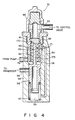
- Fig. 4 shows a flow control valve according to a second embodiment of the present invention.
- the same reference numerals as in the first embodiment denote the same parts as in the first embodiment, and a detailed description thereof will be omitted.
- Spiral choke 60 serving as an elongate spiral throttling path for throttling a flow path area is arranged between first and second pressure chambers 58 and 59 of flow control valve 51.
- Spiral choke 60 is constituted by the inner peripheral surface of sleeve 61 fitted in the upper portion of cylinder 55, and spiral grooves 63 formed on the outer peripheral surface of column 62 fitted into sleeve 61.
- Bypath passage 170 opening to the second pressure chamber 99 is formed in the central portion of column 62.
- Bypath passage 170 communicates with intermediate portions of spiral choke 60 through a plurality of bypath ports 171 (only two ports are shown in Fig. 4) formed in column 62 spaced apart from one another in the axial direction of column 62 spaced apart.
- Rod section 173 extends from the upper end of actuating valve 56 and is slidably inserted into bypath passage 170. When actuating valve 56 is located at a position of closing return port 54, rod section 173 closes all bypath ports 171. Rod section 173 sequentially opens bypath ports 171 as actuating valve 56 moves downward to increase the opening degree of return port 54.
- first pressure chamber 58 communicates with return port 54, and then part of the working oil introduced into first pressure chamber 58 is returned to the reservoir tank 13 from return port 54.
- return port 54 is opened upon displacement of actuating valve 56, bypath ports 171 are simultaneously opened by rod section 173. Therefore, part of the working oil flowing through spiral choke 60 flows out from bypath ports 171 to second pressure chamber 99 through bypath passage 170.
- the working oil is returned from return port 54 to the reservoir tank at substantially a constant ratio with respect to the inflow rate, and the outflow rate increases in accordance with an increase in the inflow rate.
- the working oil introduced in first pressure chamber 58 of flow control valve 51 is introduced into the control valve 33 while the pressure of the working oil is decreased by spiral choke 60.
- the flow resistance of the working oil flowing through spiral choke 60 is decreased when the oil temperature is high, and is increased when the oil temperature is low.
- the pressure difference generated between the upstream side (the first pressure chamber 58 side) and downstream side (the second and third pressure chamber 59 and 99 side) of spiral choke 60 decreases when the oil temperature is low, and increases when the oil temperature is high. Therefore, the inflow rate for generating a pressure difference causing return port 54 to start opening is increased with an increase in the oil temperature.
- the difference in pressure between the upstream and downstream sides of spiral choke 60 increases with a decrease in the oil temperature. Therefore, within the range of the inflow rate for causing return port 54 to be opened, the ratio of the working oil to be returned from return port 54 to the reservoir side, with respect to the inflow rate, is increased with a drop in the oil temperature. In other words, the ratio of the outflow rate from valve 51 with respect to an increase in the inflow rate to valve 51 increases in accordance with an increase in the oil temperature.
- the controlled flow rate of the working oil supplied from oil pump 26 to the control valve 33 can be increased in accordance with an increase in the oil temperature and inflow rate, as is shown in Fig. 5.
- oil temperature dependency cannot be effectively used to change the outflow rate in accordance with the inflow rate.
- the outflow rate characteristic corresponding to the inflow rate cannot be obtained within the range wherein the oil temperature dependency is generated (the region for allowing the return port to be opened).
- the outflow rate characteristic can be approximate to the ideal characteristic shown in Fig. 7.
- the flow rate characteristic shown in Fig. 6 can be obtained by, e.g., adjusting the heights of formation positions of bypath ports 171, i.e., adjusting the relationship between the positions of bypath ports 171 and the stroke of rod section 73.
- Fig. 8 shows a flow control valve according to a third embodiment of the present invention.
- the same reference numerals in the third embodiment denote the same parts as in the first and second embodiments, and a detailed description thereof will be omitted.
- spiral choke 60 arranged between first and second pressure chambers 58 and 99 of flow control valve 51 is constituted by sleeve 61 fitted in the upper portion of cylinder 55, and spiral grooves 63 formed in the outer periphery of column 62 slidably inserted into sleeve 61.
- the lower end of column 62 is coupled to the upper portion of actuating valve 56 to be slidable together with actuating valve 56.
- the working oil is returned from return port 54 to the reservoir side at a substantially constant ratio with respect to the inflow rate, thereby increasing the outflow rate in accordance with the increase in the inflow rate.
- the working oil introduced in first pressure chamber 58 of flow control valve 51 is introduced into the control valve 33 while the pressure of the working oil is decreased by spiral choke 60.
- the inflow rate necessary for generating the pressure difference causing return port 54 to be opened is increased with an increase in the oil temperature. Since the difference in pressure between the upstream and downstream sides of spiral choke 60 increases with the decrease in the oil temperature, within the range of the inflow rate for allowing return port 54 to be opened, the ratio of the working oil to be returned from return port 54 to the reservoir side with respect to the inflow rate increases with the decrease in the oil temperature. In other words, the increase in ratio of outflow rate to the increase in the inflow rate is increased with the increase in the oil temperature.
- the flow rate characteristic shown in Fig. 6 can be obtained as in the second embodiment. Accordingly, by increasing the controlled flow rate of the working oil in accordance with an increase in the oil temperature and inflow rate, the flow rate characteristic can be approximated to the ideal characteristic shown in Fig. 7. Therefore, also in the third embodiment, the oil temperature dependency of the controlled flow rate can effectively obtained. Further, the outflow rate characteristic can be changed in accordance with the inflow rate characteristic. As a result, in the four-wheel steering system shown in Fig. 1, the characteristic of rear-wheel steering angle corresponding to the vehicle speed can be kept substantially constant regardless of the oil temperatures.
Landscapes
- Engineering & Computer Science (AREA)
- Chemical & Material Sciences (AREA)
- Combustion & Propulsion (AREA)
- Transportation (AREA)
- Mechanical Engineering (AREA)
- Fluid-Pressure Circuits (AREA)
- Power Steering Mechanism (AREA)
Applications Claiming Priority (6)
| Application Number | Priority Date | Filing Date | Title |
|---|---|---|---|
| JP75639/87 | 1987-05-20 | ||
| JP1987075639U JPH0645419Y2 (ja) | 1987-05-20 | 1987-05-20 | 油圧装置の流量制御機構 |
| JP19386687U JPH079732Y2 (ja) | 1987-12-21 | 1987-12-21 | 流量制御装置 |
| JP193866/87 | 1987-12-21 | ||
| JP24664/88 | 1988-02-26 | ||
| JP1988024664U JPH01128081U (de) | 1988-02-26 | 1988-02-26 |
Publications (3)
| Publication Number | Publication Date |
|---|---|
| EP0291992A2 true EP0291992A2 (de) | 1988-11-23 |
| EP0291992A3 EP0291992A3 (en) | 1990-01-03 |
| EP0291992B1 EP0291992B1 (de) | 1995-03-15 |
Family
ID=27284739
Family Applications (1)
| Application Number | Title | Priority Date | Filing Date |
|---|---|---|---|
| EP19880108068 Expired - Lifetime EP0291992B1 (de) | 1987-05-20 | 1988-05-19 | Durchflusssteuerung |
Country Status (3)
| Country | Link |
|---|---|
| US (1) | US4887632A (de) |
| EP (1) | EP0291992B1 (de) |
| DE (1) | DE3853318T2 (de) |
Families Citing this family (9)
| Publication number | Priority date | Publication date | Assignee | Title |
|---|---|---|---|---|
| US5161959A (en) * | 1991-03-11 | 1992-11-10 | Ford Motor Company | Viscosity sensitive hydraulic pump flow control |
| US5111660A (en) * | 1991-03-11 | 1992-05-12 | Ford Motor Company | Parallel flow electronically variable orifice for variable assist power steering system |
| DE4414161C1 (de) * | 1994-04-22 | 1995-11-02 | Zahnradfabrik Friedrichshafen | Mehrachslenkanlage für Fahrzeuge |
| US6099264A (en) * | 1998-08-27 | 2000-08-08 | Itt Manufacturing Enterprises, Inc. | Pump controller |
| KR20010103493A (ko) * | 2000-05-10 | 2001-11-23 | 배길훈 | 조향펌프의 유량조절밸브 |
| US7735517B2 (en) * | 2006-12-22 | 2010-06-15 | Caterpillar Inc | Rotary-actuated electro-hydraulic valve |
| US8074558B2 (en) * | 2008-04-30 | 2011-12-13 | Caterpillar Inc. | Axial piston device having rotary displacement control |
| BR102014013015B1 (pt) * | 2014-05-29 | 2020-12-08 | Marchesan Implementos E Máquinas Agrícolas Tatú S.A. | sistema de giro aplicado nas quatro rodas para colheitadeiras de cana de açúcar |
| DE102020210048B4 (de) * | 2020-08-07 | 2024-08-29 | Zf Friedrichshafen Ag | Verfahren zum Schutz von Bauteilen einer Steer-by-wire-Lenkung sowie Steer-by-wire-Lenkung |
Family Cites Families (18)
| Publication number | Priority date | Publication date | Assignee | Title |
|---|---|---|---|---|
| FR1019078A (fr) * | 1950-05-26 | 1953-01-16 | Rectricteur automatique | |
| CH519658A (fr) * | 1970-12-28 | 1972-02-29 | Meyrat & Luisoni | Dispositif permettant de faire varier la vitesse d'écoulement d'un fluide |
| US4343324A (en) * | 1977-07-19 | 1982-08-10 | Judosha Kiki Co., Ltd. | Flow control valve |
| JPS6132850Y2 (de) * | 1978-12-05 | 1986-09-25 | ||
| JPS5847377B2 (ja) * | 1979-01-30 | 1983-10-21 | 日産自動車株式会社 | 自動車の液圧装置 |
| JPS56124560A (en) * | 1980-03-03 | 1981-09-30 | Jidosha Kiki Co Ltd | Pressurized fluid supply device for power steering arrangment |
| US4505293A (en) * | 1981-10-10 | 1985-03-19 | Bl Technology Limited | Fluid flow control valve |
| JPS58146168U (ja) * | 1982-03-26 | 1983-10-01 | 自動車機器株式会社 | 流量制御弁 |
| JPS58214469A (ja) * | 1982-06-07 | 1983-12-13 | Nissan Motor Co Ltd | 後輪操舵装置 |
| US4577728A (en) * | 1983-04-27 | 1986-03-25 | Oil Rite Corporation | Lubricant metering valve |
| BR8506815A (pt) * | 1984-07-06 | 1986-11-25 | Brunswick Valve & Control | Controlador de fluxo de liquido com pistao de pressao equilibrada para distribuicao de fluxo constante |
| DE3532602C2 (de) * | 1984-09-25 | 1994-07-28 | Jidosha Kiki Co | Strömungssteuerventil |
| JPS61241273A (ja) * | 1985-04-19 | 1986-10-27 | Tokai T R W Kk | 車速感応式パワ−ステアリング装置 |
| JP2575618B2 (ja) * | 1985-04-25 | 1997-01-29 | 株式会社豊田中央研究所 | 車両の後輪舵角制御装置 |
| JPS62113652A (ja) * | 1985-11-13 | 1987-05-25 | Nissan Motor Co Ltd | 4輪操舵車両 |
| JPH11571A (ja) * | 1997-06-10 | 1999-01-06 | Toa Kikai Seisakusho:Kk | 竪型粉砕機 |
| JP3714442B2 (ja) * | 1997-06-11 | 2005-11-09 | 株式会社サタケ | 製粉用ロール機における粉砕物の掻取装置 |
| JPH11572A (ja) * | 1997-06-13 | 1999-01-06 | Purakomu Kk | 粗砕機 |
-
1988
- 1988-05-18 US US07/195,590 patent/US4887632A/en not_active Expired - Fee Related
- 1988-05-19 DE DE3853318T patent/DE3853318T2/de not_active Expired - Fee Related
- 1988-05-19 EP EP19880108068 patent/EP0291992B1/de not_active Expired - Lifetime
Also Published As
| Publication number | Publication date |
|---|---|
| US4887632A (en) | 1989-12-19 |
| EP0291992B1 (de) | 1995-03-15 |
| DE3853318D1 (de) | 1995-04-20 |
| EP0291992A3 (en) | 1990-01-03 |
| DE3853318T2 (de) | 1995-11-16 |
Similar Documents
| Publication | Publication Date | Title |
|---|---|---|
| US5718304A (en) | Four-wheel steering system for vehicle | |
| US4681184A (en) | Hydraulic reaction force apparatus for power steering system | |
| US4212366A (en) | Power steering control device | |
| JPS60154957A (ja) | 車両用の油圧式舵取り制御装置 | |
| US4887632A (en) | Flow control apparatus | |
| US5577573A (en) | Hydraulic power steering apparatus | |
| GB2042442A (en) | Power steering valve | |
| US4830131A (en) | Variable assist power steering system | |
| US4275798A (en) | Power steering apparatus | |
| US4844126A (en) | Rotary control valve for power assist steering system | |
| US5593133A (en) | Variable assist steering pressure control valve | |
| US5147009A (en) | Steering force control apparatus of power steering system | |
| US4846296A (en) | Hydraulic fluid pressure control system for use with power assist steering | |
| US5038878A (en) | Variable assist power steering apparatus | |
| JPH0611867Y2 (ja) | 油圧装置の流量制御機構 | |
| JPH0645419Y2 (ja) | 油圧装置の流量制御機構 | |
| JPH0611868Y2 (ja) | 油圧装置の流量制御機構 | |
| KR0134787B1 (ko) | 자동차용 파워스티어링 장치 | |
| JPH0214225B2 (de) | ||
| JPH0242713B2 (de) | ||
| JPH0240542B2 (ja) | Sharyonishosarerupawaa*sutearingu | |
| US4766801A (en) | Hydraulically operated power steering system | |
| KR920002737B1 (ko) | 유량제어장치 | |
| JPH0240540B2 (de) | ||
| JPH0224702Y2 (de) |
Legal Events
| Date | Code | Title | Description |
|---|---|---|---|
| PUAI | Public reference made under article 153(3) epc to a published international application that has entered the european phase |
Free format text: ORIGINAL CODE: 0009012 |
|
| 17P | Request for examination filed |
Effective date: 19880519 |
|
| AK | Designated contracting states |
Kind code of ref document: A2 Designated state(s): DE FR GB |
|
| PUAL | Search report despatched |
Free format text: ORIGINAL CODE: 0009013 |
|
| AK | Designated contracting states |
Kind code of ref document: A3 Designated state(s): DE FR GB |
|
| 17Q | First examination report despatched |
Effective date: 19920309 |
|
| GRAA | (expected) grant |
Free format text: ORIGINAL CODE: 0009210 |
|
| AK | Designated contracting states |
Kind code of ref document: B1 Designated state(s): DE FR GB |
|
| REF | Corresponds to: |
Ref document number: 3853318 Country of ref document: DE Date of ref document: 19950420 |
|
| ET | Fr: translation filed | ||
| PLBE | No opposition filed within time limit |
Free format text: ORIGINAL CODE: 0009261 |
|
| STAA | Information on the status of an ep patent application or granted ep patent |
Free format text: STATUS: NO OPPOSITION FILED WITHIN TIME LIMIT |
|
| 26N | No opposition filed | ||
| PGFP | Annual fee paid to national office [announced via postgrant information from national office to epo] |
Ref country code: GB Payment date: 19980511 Year of fee payment: 11 Ref country code: FR Payment date: 19980511 Year of fee payment: 11 |
|
| PGFP | Annual fee paid to national office [announced via postgrant information from national office to epo] |
Ref country code: DE Payment date: 19980522 Year of fee payment: 11 |
|
| PG25 | Lapsed in a contracting state [announced via postgrant information from national office to epo] |
Ref country code: GB Free format text: LAPSE BECAUSE OF NON-PAYMENT OF DUE FEES Effective date: 19990519 |
|
| GBPC | Gb: european patent ceased through non-payment of renewal fee |
Effective date: 19990519 |
|
| PG25 | Lapsed in a contracting state [announced via postgrant information from national office to epo] |
Ref country code: FR Free format text: LAPSE BECAUSE OF NON-PAYMENT OF DUE FEES Effective date: 20000131 |
|
| PG25 | Lapsed in a contracting state [announced via postgrant information from national office to epo] |
Ref country code: DE Free format text: LAPSE BECAUSE OF NON-PAYMENT OF DUE FEES Effective date: 20000301 |
|
| REG | Reference to a national code |
Ref country code: FR Ref legal event code: ST |