EP0293065A2 - Methode und Apparat zum Auftragen von zähflüssigen Medien auf eine Fläche - Google Patents
Methode und Apparat zum Auftragen von zähflüssigen Medien auf eine Fläche Download PDFInfo
- Publication number
- EP0293065A2 EP0293065A2 EP88301339A EP88301339A EP0293065A2 EP 0293065 A2 EP0293065 A2 EP 0293065A2 EP 88301339 A EP88301339 A EP 88301339A EP 88301339 A EP88301339 A EP 88301339A EP 0293065 A2 EP0293065 A2 EP 0293065A2
- Authority
- EP
- European Patent Office
- Prior art keywords
- fluid
- air
- orifice
- spray
- web
- Prior art date
- Legal status (The legal status is an assumption and is not a legal conclusion. Google has not performed a legal analysis and makes no representation as to the accuracy of the status listed.)
- Withdrawn
Links
Images


Classifications
-
- B—PERFORMING OPERATIONS; TRANSPORTING
- B05—SPRAYING OR ATOMISING IN GENERAL; APPLYING FLUENT MATERIALS TO SURFACES, IN GENERAL
- B05D—PROCESSES FOR APPLYING FLUENT MATERIALS TO SURFACES, IN GENERAL
- B05D1/00—Processes for applying liquids or other fluent materials
- B05D1/32—Processes for applying liquids or other fluent materials using means for protecting parts of a surface not to be coated, e.g. using stencils, resists
-
- B—PERFORMING OPERATIONS; TRANSPORTING
- B05—SPRAYING OR ATOMISING IN GENERAL; APPLYING FLUENT MATERIALS TO SURFACES, IN GENERAL
- B05B—SPRAYING APPARATUS; ATOMISING APPARATUS; NOZZLES
- B05B1/00—Nozzles, spray heads or other outlets, with or without auxiliary devices such as valves, heating means
- B05B1/30—Nozzles, spray heads or other outlets, with or without auxiliary devices such as valves, heating means designed to control volume of flow, e.g. with adjustable passages
- B05B1/3093—Recirculation valves, i.e. the valve element opens a passage to the nozzle and simultaneously closes at least partially a return passage the feeding means
-
- B—PERFORMING OPERATIONS; TRANSPORTING
- B05—SPRAYING OR ATOMISING IN GENERAL; APPLYING FLUENT MATERIALS TO SURFACES, IN GENERAL
- B05B—SPRAYING APPARATUS; ATOMISING APPARATUS; NOZZLES
- B05B7/00—Spraying apparatus for discharge of liquids or other fluent materials from two or more sources, e.g. of liquid and air, of powder and gas
- B05B7/02—Spray pistols; Apparatus for discharge
- B05B7/04—Spray pistols; Apparatus for discharge with arrangements for mixing liquids or other fluent materials before discharge
- B05B7/0416—Spray pistols; Apparatus for discharge with arrangements for mixing liquids or other fluent materials before discharge with arrangements for mixing one gas and one liquid
- B05B7/0441—Spray pistols; Apparatus for discharge with arrangements for mixing liquids or other fluent materials before discharge with arrangements for mixing one gas and one liquid with one inner conduit of liquid surrounded by an external conduit of gas upstream the mixing chamber
- B05B7/0475—Spray pistols; Apparatus for discharge with arrangements for mixing liquids or other fluent materials before discharge with arrangements for mixing one gas and one liquid with one inner conduit of liquid surrounded by an external conduit of gas upstream the mixing chamber with means for deflecting the peripheral gas flow towards the central liquid flow
-
- B—PERFORMING OPERATIONS; TRANSPORTING
- B05—SPRAYING OR ATOMISING IN GENERAL; APPLYING FLUENT MATERIALS TO SURFACES, IN GENERAL
- B05B—SPRAYING APPARATUS; ATOMISING APPARATUS; NOZZLES
- B05B7/00—Spraying apparatus for discharge of liquids or other fluent materials from two or more sources, e.g. of liquid and air, of powder and gas
- B05B7/02—Spray pistols; Apparatus for discharge
- B05B7/06—Spray pistols; Apparatus for discharge with at least one outlet orifice surrounding another approximately in the same plane
- B05B7/062—Spray pistols; Apparatus for discharge with at least one outlet orifice surrounding another approximately in the same plane with only one liquid outlet and at least one gas outlet
- B05B7/066—Spray pistols; Apparatus for discharge with at least one outlet orifice surrounding another approximately in the same plane with only one liquid outlet and at least one gas outlet with an inner liquid outlet surrounded by at least one annular gas outlet
-
- B—PERFORMING OPERATIONS; TRANSPORTING
- B05—SPRAYING OR ATOMISING IN GENERAL; APPLYING FLUENT MATERIALS TO SURFACES, IN GENERAL
- B05B—SPRAYING APPARATUS; ATOMISING APPARATUS; NOZZLES
- B05B7/00—Spraying apparatus for discharge of liquids or other fluent materials from two or more sources, e.g. of liquid and air, of powder and gas
- B05B7/02—Spray pistols; Apparatus for discharge
- B05B7/08—Spray pistols; Apparatus for discharge with separate outlet orifices, e.g. to form parallel jets, i.e. the axis of the jets being parallel, to form intersecting jets, i.e. the axis of the jets converging but not necessarily intersecting at a point
- B05B7/0807—Spray pistols; Apparatus for discharge with separate outlet orifices, e.g. to form parallel jets, i.e. the axis of the jets being parallel, to form intersecting jets, i.e. the axis of the jets converging but not necessarily intersecting at a point to form intersecting jets
- B05B7/0815—Spray pistols; Apparatus for discharge with separate outlet orifices, e.g. to form parallel jets, i.e. the axis of the jets being parallel, to form intersecting jets, i.e. the axis of the jets converging but not necessarily intersecting at a point to form intersecting jets with at least one gas jet intersecting a jet constituted by a liquid or a mixture containing a liquid for controlling the shape of the latter
-
- B—PERFORMING OPERATIONS; TRANSPORTING
- B05—SPRAYING OR ATOMISING IN GENERAL; APPLYING FLUENT MATERIALS TO SURFACES, IN GENERAL
- B05B—SPRAYING APPARATUS; ATOMISING APPARATUS; NOZZLES
- B05B7/00—Spraying apparatus for discharge of liquids or other fluent materials from two or more sources, e.g. of liquid and air, of powder and gas
- B05B7/02—Spray pistols; Apparatus for discharge
- B05B7/08—Spray pistols; Apparatus for discharge with separate outlet orifices, e.g. to form parallel jets, i.e. the axis of the jets being parallel, to form intersecting jets, i.e. the axis of the jets converging but not necessarily intersecting at a point
- B05B7/0807—Spray pistols; Apparatus for discharge with separate outlet orifices, e.g. to form parallel jets, i.e. the axis of the jets being parallel, to form intersecting jets, i.e. the axis of the jets converging but not necessarily intersecting at a point to form intersecting jets
- B05B7/0846—Spray pistols; Apparatus for discharge with separate outlet orifices, e.g. to form parallel jets, i.e. the axis of the jets being parallel, to form intersecting jets, i.e. the axis of the jets converging but not necessarily intersecting at a point to form intersecting jets with jets being only jets constituted by a liquid or a mixture containing a liquid
-
- B—PERFORMING OPERATIONS; TRANSPORTING
- B05—SPRAYING OR ATOMISING IN GENERAL; APPLYING FLUENT MATERIALS TO SURFACES, IN GENERAL
- B05B—SPRAYING APPARATUS; ATOMISING APPARATUS; NOZZLES
- B05B7/00—Spraying apparatus for discharge of liquids or other fluent materials from two or more sources, e.g. of liquid and air, of powder and gas
- B05B7/02—Spray pistols; Apparatus for discharge
- B05B7/08—Spray pistols; Apparatus for discharge with separate outlet orifices, e.g. to form parallel jets, i.e. the axis of the jets being parallel, to form intersecting jets, i.e. the axis of the jets converging but not necessarily intersecting at a point
- B05B7/0876—Spray pistols; Apparatus for discharge with separate outlet orifices, e.g. to form parallel jets, i.e. the axis of the jets being parallel, to form intersecting jets, i.e. the axis of the jets converging but not necessarily intersecting at a point to form parallel jets constituted by a liquid or a mixture containing a liquid
-
- B—PERFORMING OPERATIONS; TRANSPORTING
- B05—SPRAYING OR ATOMISING IN GENERAL; APPLYING FLUENT MATERIALS TO SURFACES, IN GENERAL
- B05B—SPRAYING APPARATUS; ATOMISING APPARATUS; NOZZLES
- B05B7/00—Spraying apparatus for discharge of liquids or other fluent materials from two or more sources, e.g. of liquid and air, of powder and gas
- B05B7/24—Spraying apparatus for discharge of liquids or other fluent materials from two or more sources, e.g. of liquid and air, of powder and gas with means, e.g. a container, for supplying liquid or other fluent material to a discharge device
- B05B7/2489—Spraying apparatus for discharge of liquids or other fluent materials from two or more sources, e.g. of liquid and air, of powder and gas with means, e.g. a container, for supplying liquid or other fluent material to a discharge device an atomising fluid, e.g. a gas, being supplied to the discharge device
-
- B—PERFORMING OPERATIONS; TRANSPORTING
- B05—SPRAYING OR ATOMISING IN GENERAL; APPLYING FLUENT MATERIALS TO SURFACES, IN GENERAL
- B05C—APPARATUS FOR APPLYING FLUENT MATERIALS TO SURFACES, IN GENERAL
- B05C5/00—Apparatus in which liquid or other fluent material is projected, poured or allowed to flow on to the surface of the work
- B05C5/02—Apparatus in which liquid or other fluent material is projected, poured or allowed to flow on to the surface of the work the liquid or other fluent material being discharged through an outlet orifice by pressure, e.g. from an outlet device in contact or almost in contact, with the work
- B05C5/0245—Apparatus in which liquid or other fluent material is projected, poured or allowed to flow on to the surface of the work the liquid or other fluent material being discharged through an outlet orifice by pressure, e.g. from an outlet device in contact or almost in contact, with the work for applying liquid or other fluent material to a moving work of indefinite length, e.g. to a moving web
- B05C5/025—Apparatus in which liquid or other fluent material is projected, poured or allowed to flow on to the surface of the work the liquid or other fluent material being discharged through an outlet orifice by pressure, e.g. from an outlet device in contact or almost in contact, with the work for applying liquid or other fluent material to a moving work of indefinite length, e.g. to a moving web only at particular part of the work
-
- Y—GENERAL TAGGING OF NEW TECHNOLOGICAL DEVELOPMENTS; GENERAL TAGGING OF CROSS-SECTIONAL TECHNOLOGIES SPANNING OVER SEVERAL SECTIONS OF THE IPC; TECHNICAL SUBJECTS COVERED BY FORMER USPC CROSS-REFERENCE ART COLLECTIONS [XRACs] AND DIGESTS
- Y10—TECHNICAL SUBJECTS COVERED BY FORMER USPC
- Y10T—TECHNICAL SUBJECTS COVERED BY FORMER US CLASSIFICATION
- Y10T156/00—Adhesive bonding and miscellaneous chemical manufacture
- Y10T156/10—Methods of surface bonding and/or assembly therefor
- Y10T156/1089—Methods of surface bonding and/or assembly therefor of discrete laminae to single face of additional lamina
- Y10T156/1092—All laminae planar and face to face
- Y10T156/1093—All laminae planar and face to face with covering of discrete laminae with additional lamina
- Y10T156/1095—Opposed laminae are running length webs
Definitions
- the present invention relates to methods of and apparatus for depositing on surfaces highly viscous and lower viscosity fluids, including but not limited to hot melt fluids, for such purposes as providing adhesive layers or other coatings on moving webs or other substrate surfaces, being more particularly directed to the spraying of such fluids and the control of the same in terms of the nature of the spray particles, the extent of the spray and the contour, particularly in intermittent operation, through utilizing air jets and related parameters that convert fluid spray droplets into thin fibers or filaments of fluid, but with flexibility for generating also combinations of fibers or filaments and droplets or globules in various proportions and for various purposes.
- a slot nozzle can apply coat weights to non-woven materials and plastic films and some paper substrates to 5 grams per square meter (GSM), but only under controlled conditions. Coat weights less than 5 GSM are generally applied through spray techniques.
- the light coat weight application of hot melt to fluff pulp, and a subsequent lamination to the tissue over-wrap of a diaper provides for improved lateral and longitudinal integrity and strength, thus improving the resistance to fluff balling in the baby diaper crotch area.
- Underlying the present invention is the discovery of a technique for extrudingly spraying even lesser weight coatings of hot melt or other adhesive (say below 0.8 GSM), and in precise locations and contours, both intermittently and continuously.
- the adhesive is sprayed as fine fibers or filaments, with flexibility for combining with droplets or restricting the spray thereto, where required -- but all with a controlled, sharp and precise pattern and position on the web, with the process continuous and programmably intermittent.
- a product can receive continuous longitudinal filament application, a programmable intermittent ON/OFF repeat pattern, a series of filament applications adjacent to one another or staggered, and combined programmed intermittent and continuous application.
- a baby diaper or feminine napkin product can have continuous filament application on the left and right sides of the finished product, such as 0.5 to 1 inch in width, with intermittent filament application at the respective ends, yet located between the continuous left and right side patterns.
- the uncoated area in the center of the finished product can remain uncoated for the fluff or other customer product design requirement.
- the fluid application of the invention moreover, will be of considerably less coat weight than that accomplished today by conventional methods before-described.
- the invention is also useful for the application of room temperature liquids which are at least somewhat viscous and difficult to apply by conventional roll coaters or even slot nozzle methods, but which can be successfully applied by the filament applicating system herein. It is also possible that multiple component coating materials classified as cross-linking catalytic types can be mixed within the filament applicating head and applied to a substrate. Such materials work best when mixed within the applicating apparatus.
- the invention permits one to employ also two separate filament applicating systems, in which a coating is deposited upon a coating such that there is intermixing of the coatings on the surface of the web substrate, as later described in detail, including, for example, a base coating material such as conventional pressure-sensitive liquid adhesive from one applicator and a cross-linking activator, such as a photo-initiator from the other applicator, or another pressure-sensitive liquid adhesive of different properties, to provide strong or weaker adhesives.
- a base coating material such as conventional pressure-sensitive liquid adhesive from one applicator and a cross-linking activator, such as a photo-initiator from the other applicator, or another pressure-sensitive liquid adhesive of different properties, to provide strong or weaker adhesives.
- the multi-layer deposit of such materials does not provide natural or sufficient inter-mixing, moreover, there is also the opportunity to interject and intersect the fluid streams of two separate filament applications with each other, thus causing improved or homogeneous intermixing prior to contacting the web substrate, as also later described.
- An object of the present invention accordingly, is to provide a new and improved somewhat-to-highly viscous fluid extruded spray application method and apparatus that enable extremely lightweight hot melt adhesive and other coatings in a variety of controlled forms ranging from fibers or filaments to droplets, and combinations of the same.
- a further object is to provide an improved controlled fluid spray application technique and apparatus and products of more general utility, as well.
- the invention embraces a method of controlling the generation of somewhat-to-highly viscous fluid fibers, droplets and combinations of the same, that comprises, spraying a stream of such pressurized fluid through a fine orifice and along a predetermined direction in free flight, and simultaneously funneling a cone of pressurized air symmetrically about and against said stream, intersecting the same in its free flight below said orifice to control the nature, dimensions and pattern of the resulting fluid coating on surfaces disposed therebelow.
- spraying a stream of such pressurized fluid through a fine orifice and along a predetermined direction in free flight, and simultaneously funneling a cone of pressurized air symmetrically about and against said stream, intersecting the same in its free flight below said orifice to control the nature, dimensions and pattern of the resulting fluid coating on surfaces disposed therebelow.
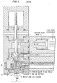
- Fig. 1 is a longitudinal section of the preferred spray valve and nozzle apparatus of the invention operating in accordance with the method underlying the same and with various air control flow paths shown in different shadings;
- fluid spray applicators While several types of fluid spray applicators may be utilized to practice the method of the invention, the same is described herein in connection with a three-way poppet valve-controlled fluid nozzle or applicator 1, Fig. 1, as of the type described in my prior United States Letters Patent No. 4,565,217, though of significantly modified design.
- the valve housing contains lower and upper fluid chambers 3′ and 3, respectively connected with a pressurized and metered fluid supply inlet line 2 and a return or exit line 2′ shown preferably provided with a pressure relief valve fluid bypass restricter assembly 4-4′, with the relief valve preset to a higher relief pressure (say of the order of 300 PSIG) and the orifice/fluid restrictor providing compressibility matching the resistance to flow by the fluid nozzle N communicating with the lower chamber 3′.
- a pressure relief valve fluid bypass restricter assembly 4-4′ with the relief valve preset to a higher relief pressure (say of the order of 300 PSIG) and the orifice/fluid restrictor providing compressibility matching the resistance to flow by the fluid nozzle N communicating with the lower chamber 3′.
- Such reciprocation is between seating of the upper section 5′ in a valve seat 3 ⁇ at the bottom of the upper chamber 3 while opening the tip T of the lower valve section 5 ⁇ above the nozzle top orifice O (causing fluid supplied to the lower chamber 3′ to exit through the nozzle N), and an open position of the upper valve section 5′, as shown, which exits the fluid supplied to the lower chamber 3′ through the upper chamber 3 and the return line 2′ (closing off fluid feed to the nozzle N by entry of the tip T into the upper nozzle opening O).
- the fluid nozzle N comprises an insert N′ having the before-mentioned upper opening O preferably of carbide construction to serve as an effective wear surface for the reciprocating valve tip T.
- the insert N′ directly communicates with a hollow needle-like tube or section N ⁇ (such as a hypodermic needle) of smaller diameter than the insert, and having an opening(s) O′ at its lower tip region for extruding a spray of the fluid passed from the supply chamber 3′ when the stem 5 is in its upper position.
- the insert opening O may be of the order of 0.75mm in diameter
- the needle tube N ⁇ may have a lesser inner diameter of about 0.35mm.
- the fluid nozzle N (N′-N ⁇ -O′) is shown preferably, though not essentially, in conical form with the nozzle orifice O′ at the converged apex of the cone and is directly embedded in the base of the poppet-valve fluid supply chamber 3′ for normal direct contact with the poppet valve stem tip T, as distinguished from remote fluid nozzle location separated by an intermediate fluid discharge plate as taught in my said earlier patent.
- This has been found advantageously to obviate the additional capacitance residing in the remote nozzle positioning which causes relatively heavy droplets of fluid to be deposited upon the moving web or other surface drawn past the nozzle N and represented at S, when the valve is closed.
- valve tip design moreover, has been found to minimize the driving of additional fluid through the nozzle during the closing action as is otherwise caused when high reciprocation rates induce a "fluid column" effect.
- the short distance between the open tip T, say of 45° convergence angle, and the insert opening O provides sufficient capacitance to absorb any such effect, and the hardness of the carbide insert N′ resists change in physical shape during impact/reciprocation against the fluid nozzle, obviating the possibility of additional fluid displacement, particularly with short valve stem strokes of the order of 0.5mm that minimize additional displacement to an acceptable level.
- the invention provides for a highly effective control of the fluid stream sprayed out of the fine nozzle opening(s) O′, in terms of the nature of the deposit on the web or other surface S moving past the nozzle and the location and contour of the same, by utilization of novel air-shaping, fanning and trimming and deflection.
- an extension to the poppet valve assembly 1 is shown located at the same bottom end as the fluid nozzle location, providing for multiple air supply inlets.
- This extension may accept up to three separate air supplies, all directed upon the fluid after it has extruded from the nozzle and is outside the same, and which are designated as:
- nozzle conical air control of the spray air enters from supply line 16 into a conical annular chamber 6 in the insert 12 which coaxially surrounds the conical fluid nozzle housing N.
- the internal shape of the nozzle air cone chamber 6 can have the same angle or shape as the fluid nozzle, or a slightly different angle or shape.
- the lower air exit aperture opening 6′ of the chamber 6, is preferably narrowed to be smaller in diameter than the inside diameter of the cone chamber shape at the aperture location, say of the order of 1.5mm in diameter, with a taper so as to provide for a non-obstructed surface area to the path of fluid displacement.
- the air inlet supply 16 is fed into two ports 6 ⁇ located at the entrance to the nozzle cone chamber and positioned 180° opposite one other, Fig. 2, for uniform pressure drop within the chamber, with the result of providing uniform air velocity at the exiting aperture or opening 6′ for funneling a cone of pressurized air symmetrically about and against the spray stream at I in free flight below the nozzle opening O′.
- the internal conical annular air chamber shape and dimensions are slightly larger than the external dimension of the fluid nozzle housing N, as shown; and by changing the relative dimensional clearance between the fluid nozzle and the nozzle air cone chamber walls, as by threaded adjustment upward or downward of the insert 12, this can increase or decrease the relative air velocity passing through the assembly.
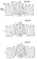
- the nozzle cone chamber aperture or opening 6′ is thus adjustable to permit the fluid nozzle tip position at O′ to remain recessed, Fig. 3A, or in the plane of or flush, Fig. 3B, or extended beyond the exit or outside surface of the nozzle conical air chamber, Fig. 3C, for purposes later explained.
- the nozzle insert member 12 may contain external threads and positioning pilot for obtaining the desired chamber position relative to the fluid nozzle tip.
- the conically directed air be funnelled to intersect the fluid spray in free flight below and outside the nozzle opening O′ as at I′, Fig. 1, after the fluid has been extruded from the nozzle, and that the air not contact, deflect, centrifuge or otherwise interfere with the longitudinal axial extrusion path of the fluid through and out of the nozzle. It has been found that the position of the cone of air will then determine the style and type of coating patterns of fluid displacement from the fluid nozzle. As an example, with the nozzle conical air chamber positioned so that the fluid nozzle tip is recessed inside the internal aperture opening 6′, Fig.
- the extruded spray particles will bond or stretch outside the nozzle into continuous lightweight fibers or filaments, as earlier explained, and of extreme thinness of the order of 0.01mm and less.
- These thin filaments are produced and deposited randomly but criss-cross, Fig. 6, for a recessed position R, Fig. 3A, of the previously stated dimensional nozzle structure, of about 0.475mm, and the deposit is of substantially uniform filament population without gaps or variations in filament coverage density.
- Fig. 6 is believed, as hereinafter explained, to be largely attributed to the synchronous volumetric fluid extrusion and synchronous volume/velocity air flow -to- process speed used with the invention.
- the compressive fluid in extrusion, expands as it exits and breaks away from the nozzle tip, and the air draws or stretches the free flight fluid into continuous filament form.
- the coating patterns will contain a combination of filament-fibers and small fluid droplets. Further adjustment to provide for fluid nozzle protrusion or extension E beyond the internal aperture opening 6′, say of the order of 0.457mm, has been found to produce predominantly droplets or globules, with ever-increasing droplet size with increasing protrusion E, Fig. 3C.
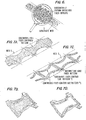
- Fanning ears may also be employed as before explained, with air entering at 18 into an extension member 14 joined with the insert 12 and with the air exiting through two external air jets 8.
- the air jets 8 are shown positioned diametrically opposite one other, Fig. 2, with the direction of air discharge designed to intersect below the external surface of the nozzle air cone chamber at I′ -- say about 1/4 ⁇ below.
- the ears 8 are downwardly and inwardly bent toward one another, as shown.
- the purpose of the fanning ears 8 is to split or fragment the fluid ejecting in free flight from the fluid nozzle, as acted upon by the nozzle cone of air. The splitting or fragmentation of the fluid stream will distribute the fluid over a wide area, greater in size than that achieved when only the cone of air is used.
- trimming air may also be provided, as previously mentioned, entering into the same extension member 14 from inlet 20 and exiting through an additional pair of 180°-opposing ears 10 of the same design as the fanning ears, but displaced circumferentially 90° to the fanning ears, Fig. 2, 2A.
- the function of the trim ears is to contain the fluid distribution from the fanning ear process, so as to provide for a more contained fluid pattern distribution and controlled pattern width. Increased trim air will cause a reduction in overall coating pattern width; whereas little or no trim air will have minimal or no effect upon the pattern width.
- a programmable cyclic volume variation of air supply to the trimming ears can provide an "hour glass" shaped pattern, if desired, Figs.
- the adhesive application may be laterally shifted to follow the cut contour shape of the diaper as in the continuous full fiber contoured pattern of Fig. 7A, resulting in the finished product of Fig. 7B.
- Two applicators may be employed, one on the left side and one on the right, simultaneously signalled to shift the coating pattern to follow the contoured shape of the diaper.
- Alternative continuous fiber contour longitudinal side patterns of "hour glass" shape may also be produced with the intermediate space uncoated, Fig.
- the intermittent adhesive application furthermore, permits the diaper maker to program the application of adhesive throughout the diaper construction. Similarly, if one of the two exit ports from the trim ears is blocked, thus permitting only one ear to be used, a deflected or wavey coating pattern can be produced when the supply air is cyclically introduced. Other balanced or unbalanced deflection effects can similarly be introduced.
- Prior fluid spray systems have been designed to operate at a fixed web speed, or a narrow range in speed change. This means that during speed ramp-up of a process, the fluid application is not applied until speed limits are reached, with the result that large quantities of scrap web material are generated at speeds less than the set limits.
- the present invention has no such limitation with its air flow devices interfacing synchronously with the fluid supply applicator and the establishing or predetermined rate ratios of fluid and air, synchronous with web line speed.
- the air supply to the trim ear zone can be made to operate in a cyclic manner, so as to produce the before-mentioned useful "hour glass" shape pattern, or other patterns as desired.
- an electronic timer system T′ operating conventional electric solenoid air valves, not shown, as described in said earlier poppet valve patent, for example, signals the poppet valve assembly to reciprocate the poppet valve stem 5 for obtaining intermittent, yet programmable, predetermined coating pattern lengths.
- the motor drive for controlling the fluid metering pump to the supply line 2, so-labelled, is controlled by the digital speed control DS that receives web line speed information from pickup P.
- the heat converter H may contain a series of longitudinal holes or passageways, radially oriented for transfer of heat into the moving air. It is important, furthermore, that the air supply temperature be maintained with close tolerance in order to insure that the fluid application environment does not vary with web speed. Loss of air temperature will cause accelerated cooling of the fluid filaments, which will result in pre-solidification of the coating material before contacting the moving web S. In such cases, angel hair or cobwebs of solidified fluid are observed and cling to adjacent apparatus, resulting in loss of production efficiency and product quality. Microprocessor temperature regulation of the heat converters is used preferably in conventional fashion for maintaining close tolerance temperature control throughout the air chambers with air volume, synchronous to machine speed, as monitored by the line-speed pick-up P.
- the fluid filament applicating system is temperature controlled, thus insuring that the control of the fluid exiting the fluid nozzle N is at a predetermined temperature irrespective of fluid volume displacement.
- the fluid displacement metering system must be synchronous, yet proportional, to line speed in order to provide close tolerance quantity of fluid rate, in which the rate of displacement is predetermined and synchronously in balance with the volume of air supplied to the nozzle cone, fanning and trim ears.
- the invention permits the application of low coat weights of contemporary hot melt adhesive products, for example, as described in said patents, in continuous and intermittent programmable patterns of filament application to web substrates at speeds of, for example, up to 300 diapers per minute, or 136 meters per minute (450 feet per minute) and higher.
- Typical substrates or webs or surfaces S are low density polyethylene, polypropylene, polyvinyl chloride, materials with extreme thermal sensitivity, and breathable fabrics, including spun-bonded or thermal bonded polypropylene and other non-woven materials.
- the accurate positive displacement metering pumps Fig. 4, preferably adjacent the nozzle head 1 as later more fully discussed, enable precise fluid displacement through the small orifice nozzle N, with the multiple air supplies introduced into the chamber surrounding the extrusion nozzle stretching and bonding the fluid spray particles into continuous monofilaments or fibers, where desired.
- the discharging air thus causes the fluid to form such nondescript lateral crisscross fiber deposits onto the moving web S, Fig. 6.
- Fluid capacitance available in flexible heated hoses of prior systems causes non-synchronous fluid application, due to the relatively long distance between metering pump at tank delivery to the coating applicating station; and the adjacent location of the metering pump and nozzle mitigates against such effects.
- the adjacent metering pump location feature also introduces improved operation in other types of fluid fiber or filament generating systems, as well.
- each filament applicator may provide application widths ranging from about 6mm to 38mm.
- Coating weights applied for the above pattern widths may be 10 mg to 50 mg per 45-50cm length of product, and we have successfully applied coat weights as low as 0.2 gms per SQM. Also, the accuracy of the coating weight has been found to be held to within 5%, plus or minus.
- Figs 8A-C the filament or fiber process of the invention is illustrated as applied to a "breathable" bandage strip or medical tape, having silicone radiation-cured (UV or EB) deposited as droplets on one side (globules of about 1gm/SM, for example) and the fibers on the opposite side, as of 45mg/45cm of adhesive pressure-sensitive material.
- a "breathable" bandage strip or medical tape having silicone radiation-cured (UV or EB) deposited as droplets on one side (globules of about 1gm/SM, for example) and the fibers on the opposite side, as of 45mg/45cm of adhesive pressure-sensitive material.
- the spray technique and control of the invention is also useful outside the field of the hot melt adhesives and the like, as before noted.
- the fiber or filament applicating system can also be most usefully employed, for example, for application of room temperature cross-linking type fluids.
- Four exemplary types of such applications are shown in Figs. 5A through D.
- a two component fluid system is shown in which two separate fluid metering supplies a and b are used at equal or proportional ratios, and are combined or mixed internally within the fiber filament applicating head 1-N-6, etc.
- the process can result in fluid catalyst reactions, as a result of the mixing, but also may be further cross-linked by further exposure to ultraviolet or electron beam radiation curing.
- FIG. 5B another two-component system is shown in which the mixing of the components occurs externally, through the intersection of the two separate fluid streams a and b, as earlier suggested.
- the fluid streams originate from individual fiber filament applicating heads 1-N-6, etc., with the respective fluid flows directed towards an intersecting point which is located either above the coating web or at the junction of the web surfaces.
- each component a and b is deposited upon a moving web, such that the second coating is deposited on top of the first coating. It is possible for one applicating head to apply a filament deposit, whereas the second may apply a non-filament droplet coating pattern. The droplet pattern, for example, will present an opportunity for coating of the filaments.
- Suitable two-component viscous fluids are, for example, pressure-sensitive liquid adhesives, such as the Dynamite Nobel (West Germany) No. 1530 adhesive with a photo-initiator such as the T.H. Goldschmidt No. A4 type, (lower viscosity range of about 500-5000CPS).
- suitable higher viscosity fluid coating materials include, for example, elastomeric rubber, acrylic, ethylene vinyl acetate, etc., holt melt, such as Findley Adhesives Company Type 990-374C, (of high viscosity ranges of about 5,000 to 50,000 cps at 150°C). Uniform filaments of the order of 0.01mm have been deposited in the controlled manner described even for wide line speed variations of from about 50 up to high line speeds of several hundred ft/minute and as high as 600 ft/minute (180 meters/minute), more or less.
Landscapes
- Nozzles (AREA)
- Application Of Or Painting With Fluid Materials (AREA)
Applications Claiming Priority (2)
| Application Number | Priority Date | Filing Date | Title |
|---|---|---|---|
| US3625487A | 1987-05-26 | 1987-05-26 | |
| US36254 | 1987-05-26 |
Publications (2)
| Publication Number | Publication Date |
|---|---|
| EP0293065A2 true EP0293065A2 (de) | 1988-11-30 |
| EP0293065A3 EP0293065A3 (de) | 1989-08-30 |
Family
ID=21887561
Family Applications (1)
| Application Number | Title | Priority Date | Filing Date |
|---|---|---|---|
| EP88301339A Withdrawn EP0293065A3 (de) | 1987-05-26 | 1988-03-31 | Methode und Apparat zum Auftragen von zähflüssigen Medien auf eine Fläche |
Country Status (9)
| Country | Link |
|---|---|
| US (1) | US4891249A (de) |
| EP (1) | EP0293065A3 (de) |
| JP (1) | JPS6458370A (de) |
| KR (1) | KR880013618A (de) |
| CN (1) | CN1030032A (de) |
| AU (1) | AU610168B2 (de) |
| BR (1) | BR8802576A (de) |
| FI (1) | FI882313A7 (de) |
| IL (1) | IL86272A (de) |
Cited By (14)
| Publication number | Priority date | Publication date | Assignee | Title |
|---|---|---|---|---|
| EP0519363A1 (de) | 1991-06-21 | 1992-12-23 | Böllhoff Verfahrenstechnik Gmbh & Co. Kg | Verfahren und Vorrichtung zum streifenförmigen Auftragen von viskosem Material |
| EP0568812A1 (de) * | 1992-04-08 | 1993-11-10 | Nordson Corporation | Verfahren und Vorrichtung zur Herstellung von luftdurchlässigen Verbundstoffen |
| EP0720871A1 (de) * | 1995-01-03 | 1996-07-10 | INT Gesellschaft mit beschränkter Haftung, Ingenieurbüro für neue Technologien, Anlagenbau, Verfahrenstechnik, ADFOSY | Vorrichtung zum streifenförmigen Auftragen von viskosem Material |
| WO1997011784A1 (en) * | 1995-09-25 | 1997-04-03 | Aplicator System Ab | A nozzle and a method for feeding thermosetting plastic |
| EP0819473A1 (de) * | 1996-07-19 | 1998-01-21 | Nordson Corporation | Verfahren und Vorrichtung zum Auftragen eines flüssigen Beschichtungsmittels in atomisierter oder nichtatomisierter Form mittels einer einzigen Düse |
| WO1998016181A1 (en) * | 1996-10-11 | 1998-04-23 | Kimberly-Clark Worldwide, Inc. | Method of applying adhesive to a leg cutout of an absorbent article |
| EP0633339A3 (de) * | 1989-06-07 | 1998-12-16 | Kimberly-Clark Worldwide, Inc. | Verfahren und Anlage für Fasern-Bildung |
| EP0819477A3 (de) * | 1996-07-16 | 1999-02-10 | Illinois Tool Works Inc. | Schmelzklebstoff-Auftragvorrichtung |
| WO1999038619A1 (en) * | 1998-01-30 | 1999-08-05 | Minnesota Mining And Manufacturing Company | Modular system for atomizing a liquid and method of atomizing a liquid |
| US6325853B1 (en) | 1996-07-19 | 2001-12-04 | Nordson Corporation | Apparatus for applying a liquid coating with an improved spray nozzle |
| EP0603748B2 (de) † | 1992-12-16 | 2003-01-02 | Kimberly-Clark Worldwide, Inc. | Verfahren und Vorrichtung zum Überwachung eines Flüssigkeitstrahles um ein Motiv zu schaffen sowie Verwendung des Verfahrens für die Herstellung eines wegwerfbaren absorbierenden Artikels |
| EP0988897A3 (de) * | 1998-09-22 | 2004-12-08 | Nordson Corporation | Selbstreinigendes Druckbegrenzungs- und Bypassventil, Austragsvorrichtung und -Verfahren |
| EP0707841B2 (de) † | 1994-10-20 | 2006-05-10 | The Procter & Gamble Company | Verfahren zum Verbinden von absorbierenden Artikeln durch Löten |
| WO2021094972A1 (en) * | 2019-11-13 | 2021-05-20 | Kci Licensing, Inc. | Devices, systems, and methods for delivering a flowable material for use as a tissue dressing |
Families Citing this family (150)
| Publication number | Priority date | Publication date | Assignee | Title |
|---|---|---|---|---|
| US4949668A (en) * | 1988-06-16 | 1990-08-21 | Kimberly-Clark Corporation | Apparatus for sprayed adhesive diaper construction |
| US4911956A (en) * | 1988-10-05 | 1990-03-27 | Nordson Corporation | Apparatus for spraying droplets of hot melt adhesive |
| US5114752A (en) * | 1988-12-12 | 1992-05-19 | Nordson Corporation | Method for gas-aided dispensing of liquid materials |
| US4987854A (en) * | 1988-12-12 | 1991-01-29 | Nordson Corporation | Apparatus for gas-aided dispensing of liquid materials |
| US5160746A (en) * | 1989-06-07 | 1992-11-03 | Kimberly-Clark Corporation | Apparatus for forming a nonwoven web |
| JPH0611275B2 (ja) * | 1989-06-29 | 1994-02-16 | ユニ・チャーム株式会社 | 使い捨てブリーフの製造方法 |
| US5124111A (en) * | 1989-09-15 | 1992-06-23 | Kimberly-Clark Corporation | Method of forming a substantially continous swirled filament |
| US4995333A (en) * | 1989-09-15 | 1991-02-26 | Kimberly-Clark Corporation | Sprayed adhesive system for applying a continuous filament of theroplastic material and imparting a swirling motion thereto |
| US5026450A (en) * | 1989-10-13 | 1991-06-25 | Nordson Corporation | Method of applying adhesive to the waist elastic material of disposable garments |
| JPH03186375A (ja) * | 1989-12-15 | 1991-08-14 | Iwata Tosouki Kogyo Kk | 処理剤塗布装置 |
| US5316836A (en) * | 1990-07-02 | 1994-05-31 | Kimberly-Clark Corporation | Sprayed adhesive diaper construction |
| US5227107A (en) * | 1990-08-07 | 1993-07-13 | Kimberly-Clark Corporation | Process and apparatus for forming nonwovens within a forming chamber |
| US5145689A (en) * | 1990-10-17 | 1992-09-08 | Exxon Chemical Patents Inc. | Meltblowing die |
| US5163620A (en) * | 1991-01-31 | 1992-11-17 | The Babcock And Wilcox Company | Nozzle for superconducting fiber production |
| US5516545A (en) * | 1991-03-26 | 1996-05-14 | Sandock; Leonard R. | Coating processes and apparatus |
| US5538754A (en) * | 1991-03-26 | 1996-07-23 | Shipley Company Inc. | Process for applying fluid on discrete substrates |
| DE4208884C2 (de) * | 1991-03-27 | 1997-03-20 | Sca Schucker Gmbh | Verfahren und Vorrichtung zum Aufbringen einer aus einem härtbaren Klebstoff bestehenden pastösen Masse |
| CA2050023C (en) * | 1991-04-22 | 2002-03-05 | Kimberly-Clark Worldwide, Inc. | Elongated element comprising helically patterned adhesive |
| US5143776A (en) * | 1991-06-24 | 1992-09-01 | The Procter & Gamble Company | Tissue laminates having adhesively joined tissue laminae |
| US5382312A (en) * | 1992-04-08 | 1995-01-17 | Nordson Corporation | Dual format adhesive apparatus for intermittently disrupting parallel, straight lines of adhesive to form a band |
| US5421921A (en) * | 1992-07-08 | 1995-06-06 | Nordson Corporation | Segmented slot die for air spray of fibers |
| CA2098784A1 (en) * | 1992-07-08 | 1994-01-09 | Bentley Boger | Apparatus and methods for applying conformal coatings to electronic circuit boards |
| EP0579012B1 (de) * | 1992-07-08 | 1998-04-01 | Nordson Corporation | Apparat und Verfahren zum Auftrag von diskontinuierlichen Beschichtungen |
| US5354378A (en) * | 1992-07-08 | 1994-10-11 | Nordson Corporation | Slot nozzle apparatus for applying coatings to bottles |
| DE69314343T2 (de) * | 1992-07-08 | 1998-03-26 | Nordson Corp | Vorrichtung und verfahren zum aufbringen von schaumbeschichtungen |
| US5418009A (en) * | 1992-07-08 | 1995-05-23 | Nordson Corporation | Apparatus and methods for intermittently applying discrete adhesive coatings |
| US5292068A (en) * | 1992-08-17 | 1994-03-08 | Nordson Corporation | One-piece, zero cavity nozzle for swirl spray of adhesive |
| US5342469A (en) * | 1993-01-08 | 1994-08-30 | Poly-Bond, Inc. | Method of making a composite with discontinuous adhesive structure |
| AU7400994A (en) * | 1993-07-26 | 1995-02-20 | Procter & Gamble Company, The | Absorbent article having improved dry/wet integrity |
| US5387208A (en) * | 1993-07-26 | 1995-02-07 | The Procter & Gamble Co. | Absorbent core having improved dry/wet integrity |
| US5368233A (en) * | 1993-09-01 | 1994-11-29 | Nordson Corporation | Spray disk for close centerline spacing |
| US5447254A (en) * | 1993-11-16 | 1995-09-05 | Nordson Corporation | Fluid dispenser with shut-off drip protection |
| US5431343A (en) * | 1994-03-15 | 1995-07-11 | Nordson Corporation | Fiber jet nozzle for dispensing viscous adhesives |
| USD366051S (en) | 1994-10-31 | 1996-01-09 | Nordson Corporation | Nozzle insert for dispensing viscous materials |
| US5598974A (en) * | 1995-01-13 | 1997-02-04 | Nordson Corporation | Reduced cavity module with interchangeable seat |
| US6037009A (en) * | 1995-04-14 | 2000-03-14 | Kimberly-Clark Worldwide, Inc. | Method for spraying adhesive |
| US5618347A (en) * | 1995-04-14 | 1997-04-08 | Kimberly-Clark Corporation | Apparatus for spraying adhesive |
| US5618566A (en) * | 1995-04-26 | 1997-04-08 | Exxon Chemical Patents, Inc. | Modular meltblowing die |
| US5728219A (en) * | 1995-09-22 | 1998-03-17 | J&M Laboratories, Inc. | Modular die for applying adhesives |
| CA2489818C (en) * | 1995-10-13 | 2007-07-24 | Nordson Corporation | A system for dispensing a viscous material onto a substrate |
| US5879751A (en) * | 1995-12-18 | 1999-03-09 | The Procter & Gamble Company | Method and apparatus for making absorbent structures having divided particulate zones |
| US5851566A (en) * | 1996-07-02 | 1998-12-22 | Avery Dennison | Applicator die |
| US5843230A (en) * | 1996-07-02 | 1998-12-01 | Avery Dennison | Sealing system for improved applicator die |
| US5843057A (en) * | 1996-07-15 | 1998-12-01 | Kimberly-Clark Worldwide, Inc. | Film-nonwoven laminate containing an adhesively-reinforced stretch-thinned film |
| US5900298A (en) * | 1996-07-22 | 1999-05-04 | Guardian Fiberglass, Inc. | Mineral fiber insulation batt impregnated with extruded synthetic fibers, and apparatus for making same |
| US6422848B1 (en) | 1997-03-19 | 2002-07-23 | Nordson Corporation | Modular meltblowing die |
| JP3238102B2 (ja) * | 1997-07-04 | 2001-12-10 | 川崎重工業株式会社 | 粘性流体の供給制御装置および方法 |
| US6045864A (en) | 1997-12-01 | 2000-04-04 | 3M Innovative Properties Company | Vapor coating method |
| US6012647A (en) * | 1997-12-01 | 2000-01-11 | 3M Innovative Properties Company | Apparatus and method of atomizing and vaporizing |
| US5964973A (en) * | 1998-01-21 | 1999-10-12 | Kimberly-Clark Worldwide, Inc. | Method and apparatus for making an elastomeric laminate web |
| US6210141B1 (en) | 1998-02-10 | 2001-04-03 | Nordson Corporation | Modular die with quick change die tip or nozzle |
| US6220843B1 (en) | 1998-03-13 | 2001-04-24 | Nordson Corporation | Segmented die for applying hot melt adhesives or other polymer melts |
| EP1407830A3 (de) | 1998-03-13 | 2004-11-03 | Nordson Corporation | Segmentierte Düse zum Auftragen von Heissschmelzklebern oder anderen Polymerschmelzen |
| US6077375A (en) * | 1998-04-15 | 2000-06-20 | Illinois Tool Works Inc. | Elastic strand coating process |
| US6296463B1 (en) | 1998-04-20 | 2001-10-02 | Nordson Corporation | Segmented metering die for hot melt adhesives or other polymer melts |
| US6422428B1 (en) | 1998-04-20 | 2002-07-23 | Nordson Corporation | Segmented applicator for hot melt adhesives or other thermoplastic materials |
| US6200635B1 (en) | 1998-08-31 | 2001-03-13 | Illinois Tool Works Inc. | Omega spray pattern and method therefor |
| US6382526B1 (en) | 1998-10-01 | 2002-05-07 | The University Of Akron | Process and apparatus for the production of nanofibers |
| US6344109B1 (en) | 1998-12-18 | 2002-02-05 | Bki Holding Corporation | Softened comminution pulp |
| US6173864B1 (en) | 1999-04-23 | 2001-01-16 | Nordson Corporation | Viscous material dispensing system and method with feedback control |
| US6291016B1 (en) * | 1999-06-02 | 2001-09-18 | Nordson Corporation | Method for increasing contact area between a viscous liquid and a substrate |
| US6264113B1 (en) * | 1999-07-19 | 2001-07-24 | Steelcase Inc. | Fluid spraying system |
| US6541063B1 (en) | 1999-11-04 | 2003-04-01 | Speedline Technologies, Inc. | Calibration of a dispensing system |
| US6602554B1 (en) | 2000-01-14 | 2003-08-05 | Illinois Tool Works Inc. | Liquid atomization method and system |
| US20020117559A1 (en) * | 2000-02-11 | 2002-08-29 | Kaligian Raymond A. | Continuous slurry dispenser apparatus |
| US7516909B2 (en) * | 2000-02-11 | 2009-04-14 | United States Gypsum Company | Continuous slurry dispenser apparatus |
| US6273345B1 (en) * | 2000-02-11 | 2001-08-14 | United States Gypsum Company | High performance slurry spray machine |
| JP4474620B2 (ja) * | 2000-03-14 | 2010-06-09 | ノードソン株式会社 | 糸状又は紐状物体に接着剤を塗布する装置と方法 |
| US6719846B2 (en) | 2000-03-14 | 2004-04-13 | Nordson Corporation | Device and method for applying adhesive filaments to materials such as strands or flat substrates |
| DE10023673B4 (de) | 2000-05-16 | 2007-11-22 | Nordson Corp., Westlake | Verteilervorrichtung zum Verteilen von Fluiden sowie Vorrichtung zum Abgeben und Auftragen von Fluid, insbesondere Klebstoff |
| US6308864B1 (en) | 2000-05-25 | 2001-10-30 | Greco Manufacturing, Inc. | Modular adhesive bead dispenser |
| US6562740B1 (en) | 2000-09-19 | 2003-05-13 | Transhield Technology As | Material for protecting articles having a nonwoven fabric bonded to a shrink film by an adhesive applied to the film in a pre-determined pattern |
| US6875712B2 (en) * | 2000-09-19 | 2005-04-05 | Transhield Technology As | Material for protecting articles having a nonwoven fabric bonded to a shrink film by an adhesive applied in a pre-determined pattern |
| US6696120B1 (en) | 2000-10-12 | 2004-02-24 | Transhield Technology As | Shrink wrap material having reinforcing scrim and method for its manufacture |
| US6378784B1 (en) | 2000-10-27 | 2002-04-30 | Nordson Corporation | Dispensing system using a die tip having an air foil |
| ITTO20010278A1 (it) * | 2001-03-23 | 2002-09-23 | Anest Iwata Europ Srl | Pistola automatica a spruzzo. |
| US6520425B1 (en) | 2001-08-21 | 2003-02-18 | The University Of Akron | Process and apparatus for the production of nanofibers |
| US6811095B2 (en) * | 2002-01-07 | 2004-11-02 | Illinois Tool Works Inc. | All plastic air cap for hot melt adhesive applicator |
| US6695992B2 (en) | 2002-01-22 | 2004-02-24 | The University Of Akron | Process and apparatus for the production of nanofibers |
| US7617951B2 (en) * | 2002-01-28 | 2009-11-17 | Nordson Corporation | Compact heated air manifolds for adhesive application |
| DE10205005A1 (de) * | 2002-02-07 | 2003-08-21 | Neumag Gmbh & Co Kg | Verfahren und Vorrichtung zum Benetzen eines laufenden Filamentbündels |
| US6918993B2 (en) * | 2002-07-10 | 2005-07-19 | Kimberly-Clark Worldwide, Inc. | Multi-ply wiping products made according to a low temperature delamination process |
| US20040081794A1 (en) * | 2002-10-29 | 2004-04-29 | Titone David M. | Method for applying adhesive filaments to multiple strands of material and articles formed with the method |
| US20040148763A1 (en) * | 2002-12-11 | 2004-08-05 | Peacock David S. | Dispensing system and method |
| US7060155B2 (en) * | 2002-12-24 | 2006-06-13 | Owens Corning Fiberglas Technology, Inc. | Method and apparatus for soft skin encapsulation |
| US6905563B2 (en) * | 2002-12-24 | 2005-06-14 | Owens Corning Fiberglas Technology, Inc. | Method and apparatus for melt-blown fiber encapsulation |
| SE0301920L (sv) * | 2003-06-30 | 2004-12-07 | Baldwin Jimek Ab | Spraymunstycke |
| EP1512777B1 (de) * | 2003-08-23 | 2009-11-18 | Reifenhäuser GmbH & Co. KG Maschinenfabrik | Vorrichtung zur Erzeugung von Mehrkomponentenfasern, insbesondere von Bikomponentenfasern |
| US6991706B2 (en) | 2003-09-02 | 2006-01-31 | Kimberly-Clark Worldwide, Inc. | Clothlike pattern densified web |
| MXPA06002422A (es) * | 2003-09-02 | 2006-06-20 | Kimberly Clark Co | Aglutinados de olor bajo que pueden ser curados a la temperatura ambiente. |
| US20050045293A1 (en) * | 2003-09-02 | 2005-03-03 | Hermans Michael Alan | Paper sheet having high absorbent capacity and delayed wet-out |
| US7189307B2 (en) * | 2003-09-02 | 2007-03-13 | Kimberly-Clark Worldwide, Inc. | Low odor binders curable at room temperature |
| US20050242108A1 (en) | 2004-04-30 | 2005-11-03 | Nordson Corporation | Liquid dispenser having individualized process air control |
| US20050284338A1 (en) * | 2004-06-01 | 2005-12-29 | Dwyer Patrick A | Hot melt adhesive |
| US7297231B2 (en) * | 2004-07-15 | 2007-11-20 | Kimberly-Clark Worldwide, Inc. | Binders curable at room temperature with low blocking |
| DE102004058140B4 (de) * | 2004-11-25 | 2007-09-20 | Tesa Ag | Hydroaktives Pflaster mit dreidimensionaler Wirrfadenbeschichtung |
| JP2007099359A (ja) * | 2005-10-06 | 2007-04-19 | Fukushima Insatsu Kogyo Kk | 樹脂の微細疎ら塗装をした包装資材とその製造方法 |
| US7621465B2 (en) * | 2005-11-10 | 2009-11-24 | Nordson Corporation | Air annulus cut off nozzle to reduce stringing and method |
| EP2289634B1 (de) * | 2006-01-06 | 2015-12-16 | Nordson Corporation | Flüssigkeitsspender mit individualisierter Prozessluftsteuerung |
| US7718251B2 (en) | 2006-03-10 | 2010-05-18 | Amesbury Group, Inc. | Systems and methods for manufacturing reinforced weatherstrip |
| CN101657265B (zh) * | 2007-04-03 | 2013-10-30 | 诺信公司 | 构造为耐磨的防护构件以及喷嘴组件 |
| DE102008027259A1 (de) * | 2008-06-06 | 2009-12-17 | Focke & Co.(Gmbh & Co. Kg) | Verfahren und Vorrichtung zur Herstellung von Zigarettenpackungen |
| WO2010032984A2 (ko) * | 2008-09-22 | 2010-03-25 | Na Jong Kap | 잉크 점도 조절 장치 |
| KR101039494B1 (ko) | 2008-09-22 | 2011-06-08 | 나종갑 | 잉크 점도 조절 장치 |
| US20100117254A1 (en) * | 2008-11-07 | 2010-05-13 | Palo Alto Research Center Incorporated | Micro-Extrusion System With Airjet Assisted Bead Deflection |
| US9085384B2 (en) * | 2009-06-14 | 2015-07-21 | Nulabel Technologies, Inc. | Liner-free label and systems |
| US8292863B2 (en) | 2009-10-21 | 2012-10-23 | Donoho Christopher D | Disposable diaper with pouches |
| JP5652167B2 (ja) * | 2010-12-01 | 2015-01-14 | トヨタ紡織株式会社 | 溶融紡糸装置及び溶融紡糸方法 |
| US9034425B2 (en) | 2012-04-11 | 2015-05-19 | Nordson Corporation | Method and apparatus for applying adhesive on an elastic strand in a personal disposable hygiene product |
| US9682392B2 (en) | 2012-04-11 | 2017-06-20 | Nordson Corporation | Method for applying varying amounts or types of adhesive on an elastic strand |
| US8968517B2 (en) | 2012-08-03 | 2015-03-03 | First Quality Tissue, Llc | Soft through air dried tissue |
| KR20150117654A (ko) * | 2013-01-04 | 2015-10-20 | 피쉬맨 코포레이션 | 카데터 팁 코팅 시스템 |
| US20140263403A1 (en) * | 2013-03-15 | 2014-09-18 | Nordson Corporation | Liquid Dispensing Syringe |
| CN104338626B (zh) * | 2013-08-07 | 2019-01-04 | 江西众光照明科技有限公司 | 一种led封装喷雾脱模设备 |
| CN104936706B (zh) * | 2013-09-17 | 2017-12-22 | 深圳市腾科系统技术有限公司 | 一种组合式热熔胶喷头 |
| US9108214B2 (en) * | 2013-10-31 | 2015-08-18 | Nordson Corporation | Dispensing module having a sealing zone and method for dispensing an adhesive |
| US9126223B2 (en) | 2013-10-31 | 2015-09-08 | Nordson Corporation | Dispensing module and method for dispensing an adhesive |
| JP6230893B2 (ja) * | 2013-12-10 | 2017-11-15 | 株式会社ヒラノテクシード | 間欠塗工装置 |
| WO2015176063A1 (en) | 2014-05-16 | 2015-11-19 | First Quality Tissue, Llc | Flushable wipe and method of forming the same |
| MX369078B (es) | 2014-11-12 | 2019-10-28 | First Quality Tissue Llc | Fibra de cannabis, estructuras celulósicas absorbentes que contienen fibra de cannabis y métodos para producir las mismas. |
| EP3221510A4 (de) | 2014-11-24 | 2018-05-23 | First Quality Tissue, LLC | Durch ein strukturiertes gewebe und energieeffizientes pressen hergestelltes weichgewebe |
| MX381133B (es) | 2014-12-05 | 2025-03-12 | Structured I Llc | Proceso de fabricación de bandas de fabricar papel por el uso de tecnología de impresión 3d. |
| US9719213B2 (en) | 2014-12-05 | 2017-08-01 | First Quality Tissue, Llc | Towel with quality wet scrubbing properties at relatively low basis weight and an apparatus and method for producing same |
| CN107923217A (zh) | 2015-02-13 | 2018-04-17 | 埃美斯博瑞集团有限公司 | 低压缩力的tpe耐候性密封件 |
| US10421095B2 (en) * | 2015-05-20 | 2019-09-24 | Illinois Tool Works Inc. | Modular fluid application device compatible with different nozzle configurations |
| US10130972B2 (en) | 2015-09-09 | 2018-11-20 | Illinois Tool Works Inc. | High speed intermittent barrier nozzle |
| US10538882B2 (en) | 2015-10-13 | 2020-01-21 | Structured I, Llc | Disposable towel produced with large volume surface depressions |
| WO2017066465A1 (en) | 2015-10-13 | 2017-04-20 | First Quality Tissue, Llc | Disposable towel produced with large volume surface depressions |
| EP3362366A4 (de) | 2015-10-14 | 2019-06-19 | First Quality Tissue, LLC | Gebündeltes produkt sowie system und verfahren zu dessen herstellung |
| WO2017068625A1 (ja) * | 2015-10-19 | 2017-04-27 | 東芝三菱電機産業システム株式会社 | 成膜装置 |
| KR20180134855A (ko) | 2016-02-11 | 2018-12-19 | 스트럭?드 아이, 엘엘씨 | 제지 기계를 위한 중합체 층을 포함하는 벨트 또는 직물 |
| US20170314206A1 (en) | 2016-04-27 | 2017-11-02 | First Quality Tissue, Llc | Soft, low lint, through air dried tissue and method of forming the same |
| CA3168412C (en) | 2016-08-26 | 2024-10-22 | Structured I, Llc | METHOD FOR PRODUCING ABSORBENT STRUCTURES EXHIBITING HIGH RESISTANCE IN THE WET STATE, HIGH ABSORPTION CAPACITY AND FLEXIBILITY |
| MX2019002752A (es) | 2016-09-12 | 2019-08-29 | Dispositivo de formacion de un activo depositado por via humeda utilizando un tejido estructurado como hilo externo. | |
| JPWO2018066720A1 (ja) * | 2016-10-05 | 2018-10-04 | 株式会社サンツール | 伸縮性複合シート、伸縮性複合シートの製造方法および伸縮性複合シートの製造装置 |
| US11583489B2 (en) | 2016-11-18 | 2023-02-21 | First Quality Tissue, Llc | Flushable wipe and method of forming the same |
| US10751748B1 (en) | 2017-07-19 | 2020-08-25 | 4 C's Spray Equipment Rental, LLC | Adhesive dispensing system and method |
| US10619309B2 (en) | 2017-08-23 | 2020-04-14 | Structured I, Llc | Tissue product made using laser engraved structuring belt |
| DE102018114748A1 (de) | 2018-06-20 | 2019-12-24 | Voith Patent Gmbh | Laminierte Papiermaschinenbespannung |
| US11697538B2 (en) | 2018-06-21 | 2023-07-11 | First Quality Tissue, Llc | Bundled product and system and method for forming the same |
| US11738927B2 (en) | 2018-06-21 | 2023-08-29 | First Quality Tissue, Llc | Bundled product and system and method for forming the same |
| US10948824B2 (en) * | 2018-06-28 | 2021-03-16 | Taiwan Semiconductor Manufacturing Co., Ltd. | Dispensing nozzle design and dispensing method thereof |
| US12553189B2 (en) | 2019-05-03 | 2026-02-17 | First Quality Tissue, Llc | Absorbent structures with high strength and low MD stretch |
| MX2023007263A (es) | 2020-12-17 | 2023-10-09 | First Quality Tissue Llc | Estructuras absorbentes desechables tendidas en húmedo con alta resistencia en húmedo y procedimiento de producción de las mismas. |
| CN114308566B (zh) * | 2022-03-17 | 2022-05-31 | 江苏高凯精密流体技术股份有限公司 | 一种用于输送颗粒胶水的可变间隙螺旋式送料装置 |
| TW202419708A (zh) | 2022-06-16 | 2024-05-16 | 美商第一高質棉紗公司 | 具有高濕強度的濕簾紋紙和紙板產品及其製造方法 |
| WO2023244871A1 (en) | 2022-06-16 | 2023-12-21 | First Quality Tissue, Llc | Wet laid paper and paperboard products with high wet strength and method of making the same |
| US11976421B2 (en) | 2022-06-16 | 2024-05-07 | First Quality Tissue, Llc | Wet laid disposable absorbent structures with high wet strength and method of making the same |
| US11952721B2 (en) | 2022-06-16 | 2024-04-09 | First Quality Tissue, Llc | Wet laid disposable absorbent structures with high wet strength and method of making the same |
| CN116059517B (zh) * | 2023-02-07 | 2026-01-02 | 中国科学院苏州生物医学工程技术研究所 | 生物墨水喷涂装置 |
Family Cites Families (20)
| Publication number | Priority date | Publication date | Assignee | Title |
|---|---|---|---|---|
| US2626122A (en) * | 1951-07-03 | 1953-01-20 | Vilbiss Co | Spray gun valve |
| US2740670A (en) * | 1951-12-29 | 1956-04-03 | Harder August | Spray guns |
| GB837455A (en) * | 1956-06-22 | 1960-06-15 | Raymond Mercher | Spraying apparatus |
| GB977077A (en) * | 1963-11-20 | 1964-12-02 | Alfred Bullows & Sons Ltd | Liquid spraying apparatus |
| DE1458002B2 (de) * | 1964-11-18 | 1972-02-24 | Badische Anilin- & Soda-Fabrik Ag, 6700 Ludwigshafen | Vorrichtung zum Zerstäuben von Flüssigkeiten |
| BE756865A (fr) * | 1970-01-05 | 1971-03-01 | Acumeter Lab | Appareil applicateur de fluide |
| US4020194A (en) * | 1974-12-30 | 1977-04-26 | Acumeter Laboratories, Inc. | Process for discontinuous coating of a web by periodic deflection thereof against a fluid coating |
| US4013037A (en) * | 1975-03-27 | 1977-03-22 | Airprint Systems, Inc. | Apparatus for controllably applying liquids to a moving surface |
| DE2924174C2 (de) * | 1979-06-15 | 1984-04-19 | Heinrich Bühnen KG Maschinenfabrik, Im- und Export, 2800 Bremen | Verfahren und Düse eines Gerätes zum Aufbringen eines Klebers auf ein Substrat |
| JPS58183958A (ja) * | 1982-04-13 | 1983-10-27 | ノ−ドソン・コ−ポレ−シヨン | 吹付塗装装置および方法 |
| US4431690A (en) * | 1982-04-23 | 1984-02-14 | Nordson Corporation | Controller for uniform fluid dispensing |
| US4476165A (en) * | 1982-06-07 | 1984-10-09 | Acumeter Laboratories, Inc. | Method of and apparatus for multi-layer viscous fluid deposition such as for the application of adhesives and the like |
| JPS5946159A (ja) * | 1982-09-03 | 1984-03-15 | Asahi Okuma Ind Co Ltd | エアレススプレイ塗装方法及びエアレス塗装用スプレイガン |
| JPS5992055A (ja) * | 1982-11-17 | 1984-05-28 | Tokai Rika Co Ltd | グリスの塗布方法および装置 |
| JPS59222268A (ja) * | 1983-05-31 | 1984-12-13 | Sumitomo Chem Co Ltd | 表面が凹凸化された製品の製造方法 |
| US4565217A (en) * | 1983-06-30 | 1986-01-21 | Acumeter Laboratories, Inc. | Three-way poppet valve, method and apparatus |
| JPS6142373A (ja) * | 1984-08-07 | 1986-02-28 | Mitsui Toatsu Chem Inc | スエ−ド調又はフエルト調模様の形成方法 |
| JP2543337B2 (ja) * | 1985-07-22 | 1996-10-16 | ノ−ドソン株式会社 | 熱可塑性接着剤の塗布方法 |
| US4650119A (en) * | 1985-11-26 | 1987-03-17 | Binks Manufacturing Company | Air spray gun |
| US4711683A (en) * | 1987-03-09 | 1987-12-08 | Paper Converting Machine Company | Method and apparatus for making elastic diapers |
-
1988
- 1988-03-24 US US07/198,689 patent/US4891249A/en not_active Expired - Fee Related
- 1988-03-31 EP EP88301339A patent/EP0293065A3/de not_active Withdrawn
- 1988-05-04 IL IL86272A patent/IL86272A/xx unknown
- 1988-05-12 AU AU16087/88A patent/AU610168B2/en not_active Ceased
- 1988-05-17 FI FI882313A patent/FI882313A7/fi not_active IP Right Cessation
- 1988-05-25 JP JP63128137A patent/JPS6458370A/ja active Pending
- 1988-05-26 KR KR1019880006195A patent/KR880013618A/ko not_active Withdrawn
- 1988-05-26 CN CN88103103A patent/CN1030032A/zh active Pending
- 1988-05-26 BR BR8802576A patent/BR8802576A/pt unknown
Cited By (21)
| Publication number | Priority date | Publication date | Assignee | Title |
|---|---|---|---|---|
| EP0633339A3 (de) * | 1989-06-07 | 1998-12-16 | Kimberly-Clark Worldwide, Inc. | Verfahren und Anlage für Fasern-Bildung |
| EP0519363A1 (de) | 1991-06-21 | 1992-12-23 | Böllhoff Verfahrenstechnik Gmbh & Co. Kg | Verfahren und Vorrichtung zum streifenförmigen Auftragen von viskosem Material |
| EP0568812A1 (de) * | 1992-04-08 | 1993-11-10 | Nordson Corporation | Verfahren und Vorrichtung zur Herstellung von luftdurchlässigen Verbundstoffen |
| US5294258A (en) * | 1992-04-08 | 1994-03-15 | Nordson Corporation | Apparatus for producing an integral adhesive matrix |
| EP0603748B2 (de) † | 1992-12-16 | 2003-01-02 | Kimberly-Clark Worldwide, Inc. | Verfahren und Vorrichtung zum Überwachung eines Flüssigkeitstrahles um ein Motiv zu schaffen sowie Verwendung des Verfahrens für die Herstellung eines wegwerfbaren absorbierenden Artikels |
| EP0843037B1 (de) * | 1992-12-16 | 2004-08-18 | Kimberly-Clark Worldwide, Inc. | Verfahren und Vorrichtung zum Steuern eines Flüssigkeitstrahls um ein Muster zu schaffen |
| EP0707841B2 (de) † | 1994-10-20 | 2006-05-10 | The Procter & Gamble Company | Verfahren zum Verbinden von absorbierenden Artikeln durch Löten |
| EP0720871A1 (de) * | 1995-01-03 | 1996-07-10 | INT Gesellschaft mit beschränkter Haftung, Ingenieurbüro für neue Technologien, Anlagenbau, Verfahrenstechnik, ADFOSY | Vorrichtung zum streifenförmigen Auftragen von viskosem Material |
| WO1997011784A1 (en) * | 1995-09-25 | 1997-04-03 | Aplicator System Ab | A nozzle and a method for feeding thermosetting plastic |
| RU2152265C2 (ru) * | 1995-09-25 | 2000-07-10 | Апликатор Систем АБ | Насадок |
| AU710076B2 (en) * | 1995-09-25 | 1999-09-16 | Aplicator System Ab | A nozzle and a method for feeding thermosetting plastic |
| US6113013A (en) * | 1995-09-25 | 2000-09-05 | Aplicator System Ab | Nozzle and a method for feeding thermosetting plastic |
| EP0819477A3 (de) * | 1996-07-16 | 1999-02-10 | Illinois Tool Works Inc. | Schmelzklebstoff-Auftragvorrichtung |
| US6325853B1 (en) | 1996-07-19 | 2001-12-04 | Nordson Corporation | Apparatus for applying a liquid coating with an improved spray nozzle |
| EP0819473A1 (de) * | 1996-07-19 | 1998-01-21 | Nordson Corporation | Verfahren und Vorrichtung zum Auftragen eines flüssigen Beschichtungsmittels in atomisierter oder nichtatomisierter Form mittels einer einzigen Düse |
| US5932284A (en) * | 1996-10-11 | 1999-08-03 | Kimberly-Clark Worldwide, Inc. | Method of applying adhesive to an edge of moving web |
| WO1998016181A1 (en) * | 1996-10-11 | 1998-04-23 | Kimberly-Clark Worldwide, Inc. | Method of applying adhesive to a leg cutout of an absorbent article |
| US6056213A (en) * | 1998-01-30 | 2000-05-02 | 3M Innovative Properties Company | Modular system for atomizing a liquid |
| WO1999038619A1 (en) * | 1998-01-30 | 1999-08-05 | Minnesota Mining And Manufacturing Company | Modular system for atomizing a liquid and method of atomizing a liquid |
| EP0988897A3 (de) * | 1998-09-22 | 2004-12-08 | Nordson Corporation | Selbstreinigendes Druckbegrenzungs- und Bypassventil, Austragsvorrichtung und -Verfahren |
| WO2021094972A1 (en) * | 2019-11-13 | 2021-05-20 | Kci Licensing, Inc. | Devices, systems, and methods for delivering a flowable material for use as a tissue dressing |
Also Published As
| Publication number | Publication date |
|---|---|
| BR8802576A (pt) | 1988-12-20 |
| CN1030032A (zh) | 1989-01-04 |
| AU610168B2 (en) | 1991-05-16 |
| US4891249A (en) | 1990-01-02 |
| JPS6458370A (en) | 1989-03-06 |
| AU1608788A (en) | 1988-12-01 |
| FI882313A7 (fi) | 1988-11-27 |
| IL86272A0 (en) | 1988-11-15 |
| KR880013618A (ko) | 1988-12-21 |
| EP0293065A3 (de) | 1989-08-30 |
| FI882313A0 (fi) | 1988-05-17 |
| IL86272A (en) | 1992-03-29 |
Similar Documents
| Publication | Publication Date | Title |
|---|---|---|
| US4891249A (en) | Method of and apparatus for somewhat-to-highly viscous fluid spraying for fiber or filament generation, controlled droplet generation, and combinations of fiber and droplet generation, intermittent and continuous, and for air-controlling spray deposition | |
| US4996091A (en) | Product comprising substrate bearing continuous extruded fiber forming random crisscross pattern layer | |
| KR0131337B1 (ko) | 기저귀의 스프레이 접착방법 및 장치 | |
| AU727472B2 (en) | Omega spray pattern and method therefor | |
| EP0417815B1 (de) | Verfahren und Anlage für die Auftragung der ausgesuchten Muster auf einer Grundlage | |
| US6074597A (en) | Meltblowing method and apparatus | |
| US5728219A (en) | Modular die for applying adhesives | |
| JP2713542B2 (ja) | 離散的なコーティングを塗布する装置及び方法 | |
| EP2679313B1 (de) | Verfahren und Vorrichtung zum Auftragen von Leim auf einem elastischen Faden in einem Einweghygieneprodukt | |
| JP2002505951A (ja) | ホットメルト接着剤または他のポリマー溶融物を塗布するためのセグメントダイ | |
| US5124111A (en) | Method of forming a substantially continous swirled filament | |
| US7886989B2 (en) | Liquid material dispensing apparatus and method utilizing pulsed pressurized air | |
| US9682392B2 (en) | Method for applying varying amounts or types of adhesive on an elastic strand | |
| EP3210675A1 (de) | Verfahren, vorrichtung und düse zur applikation unterschiedlicher mengen oder arten von klebstoff auf einen elastischen faden | |
| US20040081794A1 (en) | Method for applying adhesive filaments to multiple strands of material and articles formed with the method | |
| KR102328514B1 (ko) | 이동중인 베이스 웹 상에 있는 접착제 패턴 | |
| WO2003086949A2 (en) | Applicator and nozzle for dispensing controlled patterns of liquid material | |
| US20070102841A1 (en) | Applicators and methods for dispensing a liquid material | |
| EP0470594A1 (de) | Verfahren zur Herstellung eines Vliesstoffes | |
| MXPA99007994A (en) | Spray pattern on omega and method for e |
Legal Events
| Date | Code | Title | Description |
|---|---|---|---|
| PUAI | Public reference made under article 153(3) epc to a published international application that has entered the european phase |
Free format text: ORIGINAL CODE: 0009012 |
|
| AK | Designated contracting states |
Kind code of ref document: A2 Designated state(s): AT BE CH DE ES FR GB GR IT LI NL SE |
|
| PUAL | Search report despatched |
Free format text: ORIGINAL CODE: 0009013 |
|
| AK | Designated contracting states |
Kind code of ref document: A3 Designated state(s): AT BE CH DE ES FR GB GR IT LI NL SE |
|
| 17P | Request for examination filed |
Effective date: 19900115 |
|
| 17Q | First examination report despatched |
Effective date: 19910128 |
|
| STAA | Information on the status of an ep patent application or granted ep patent |
Free format text: STATUS: THE APPLICATION IS DEEMED TO BE WITHDRAWN |
|
| 18D | Application deemed to be withdrawn |
Effective date: 19920930 |