EP0294304B1 - Vorrichtung und Verfahren zum Abdichten und Auskleiden von Tunneln - Google Patents
Vorrichtung und Verfahren zum Abdichten und Auskleiden von Tunneln Download PDFInfo
- Publication number
- EP0294304B1 EP0294304B1 EP88420180A EP88420180A EP0294304B1 EP 0294304 B1 EP0294304 B1 EP 0294304B1 EP 88420180 A EP88420180 A EP 88420180A EP 88420180 A EP88420180 A EP 88420180A EP 0294304 B1 EP0294304 B1 EP 0294304B1
- Authority
- EP
- European Patent Office
- Prior art keywords
- sheet
- panels
- sealing
- concrete
- tunnel
- Prior art date
- Legal status (The legal status is an assumption and is not a legal conclusion. Google has not performed a legal analysis and makes no representation as to the accuracy of the status listed.)
- Expired - Lifetime
Links
- 238000007789 sealing Methods 0.000 title claims abstract description 28
- 238000000034 method Methods 0.000 title claims description 17
- 239000004567 concrete Substances 0.000 claims abstract description 31
- 239000002184 metal Substances 0.000 claims 1
- 238000009412 basement excavation Methods 0.000 abstract description 22
- 238000005266 casting Methods 0.000 abstract 1
- 239000011248 coating agent Substances 0.000 description 15
- 238000000576 coating method Methods 0.000 description 15
- 238000004078 waterproofing Methods 0.000 description 12
- 238000009415 formwork Methods 0.000 description 4
- 238000009434 installation Methods 0.000 description 4
- 230000002093 peripheral effect Effects 0.000 description 4
- 239000011150 reinforced concrete Substances 0.000 description 3
- 239000011378 shotcrete Substances 0.000 description 3
- 238000010276 construction Methods 0.000 description 2
- 239000006260 foam Substances 0.000 description 2
- 238000002347 injection Methods 0.000 description 2
- 239000007924 injection Substances 0.000 description 2
- 238000009413 insulation Methods 0.000 description 2
- 230000007774 longterm Effects 0.000 description 2
- 230000000284 resting effect Effects 0.000 description 2
- 125000006850 spacer group Chemical group 0.000 description 2
- 239000011800 void material Substances 0.000 description 2
- XLYOFNOQVPJJNP-UHFFFAOYSA-N water Substances O XLYOFNOQVPJJNP-UHFFFAOYSA-N 0.000 description 2
- 241001080024 Telles Species 0.000 description 1
- 238000000605 extraction Methods 0.000 description 1
- 230000001788 irregular Effects 0.000 description 1
- 238000004519 manufacturing process Methods 0.000 description 1
- 230000003647 oxidation Effects 0.000 description 1
- 238000007254 oxidation reaction Methods 0.000 description 1
- 239000011435 rock Substances 0.000 description 1
- 230000035939 shock Effects 0.000 description 1
- 239000007921 spray Substances 0.000 description 1
- 238000005507 spraying Methods 0.000 description 1
Images


Classifications
-
- E—FIXED CONSTRUCTIONS
- E21—EARTH OR ROCK DRILLING; MINING
- E21D—SHAFTS; TUNNELS; GALLERIES; LARGE UNDERGROUND CHAMBERS
- E21D11/00—Lining tunnels, galleries or other underground cavities, e.g. large underground chambers; Linings therefor; Making such linings in situ, e.g. by assembling
- E21D11/38—Waterproofing; Heat insulating; Soundproofing; Electric insulating
- E21D11/383—Waterproofing; Heat insulating; Soundproofing; Electric insulating by applying waterproof flexible sheets; Means for fixing the sheets to the tunnel or cavity wall
-
- E—FIXED CONSTRUCTIONS
- E21—EARTH OR ROCK DRILLING; MINING
- E21D—SHAFTS; TUNNELS; GALLERIES; LARGE UNDERGROUND CHAMBERS
- E21D11/00—Lining tunnels, galleries or other underground cavities, e.g. large underground chambers; Linings therefor; Making such linings in situ, e.g. by assembling
- E21D11/04—Lining with building materials
- E21D11/10—Lining with building materials with concrete cast in situ; Shuttering also lost shutterings, e.g. made of blocks, of metal plates or other equipment adapted therefor
Definitions
- the present invention relates to tunnel sealing and lining devices which make it possible to protect the roadway from water inflows and falling blocks from the excavation.
- One of them consists in protecting the sealing sheet by a vault made of galvanized sheets.
- the protection thus obtained is fragile and not very durable, the users being poorly protected from the risks of falling blocks from the excavation.
- the tunnel lining can also consist of a thin prefabricated reinforced concrete vault, broken down into larger or smaller elements. These vaults are weakened due to the oxidation of the fastenings of the prefabricated elements, so that accidental shocks have caused the fall of this heavy coating on users.
- a last method consists in protecting the waterproofing sheet fixed on the periphery of the excavation by a projection of reinforced concrete by a welded mesh of large section.
- the concrete which is put in place very slowly because of its little adhesion to the waterproofing sheet, must follow the profile of the excavation and consequently the vault obtained is very irregular and bumpy.
- the waterproofing / coating complex consists of a waterproofing sheet protected by a shell of independent sprayed concrete and of the ground and the waterproofing.
- means are used to avoid having to fix the waterproofing sheet to the ground and to obtain a shell of desired geometric shape and constant thickness whatever the profile of the rock excavation.
- These means make it possible to give the underside of this projected concrete hull a smooth and regular appearance.
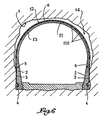
- the hull obtained is monolithic and rests on two coffered concrete bases which reinforce the coating in its part most exposed to accidental impact.
- the coating has solidity and aesthetic characteristics which allow it to replace the protection made up of a vault in boxed concrete, but it is quick to install, of lower cost and does not have the disadvantages of other known methods.
- the waterproofing / coating complex consists of a sheet of closed-cell foam forming the waterproofing, which rests on a light framework serving as support for the production of a shotcrete shell.
- the shape and thickness of this hull are those given by the light frame.
- the framework is associated on its upper surface with a peripheral envelope intended to stop and hang the concrete during its projection. Its lower surface is provided with means which allow the adjustment of the concrete at the end of the projection.
- the concrete surface is finally floated so as to present a smooth and regular appearance.
- Document CH-A-505254 discloses an articulated formwork capable of allowing the construction of an internal coating of concrete as indicated above.
- Document FR-A-2470243 shows the installation of a sealing sheet directly on the excavation by pressurization from inside the tunnel before the actual vault is formed.
- the sealing sheet is temporarily held by means of a scaffolding, which is then replaced by the aforementioned frame, the panels disposed between the latter and the sealing sheet comprising spacers facing the sheet to form a second improving void. thermal insulation of the coating.
- the formwork and the pouring of the concrete constituting said bases are proceeded with.
- Their upper parts called “flat” 5 are erected and leveled according to the longitudinal profile of the excavation 1 at a desired height.
- the vault seal is placed, consisting of a sheet of closed-cell foam 6 which is heat-sealed to the two seal sheets 3 located behind the bases 2. As illustrated in FIG. 2, the sheet 6 is temporarily supported by a scaffold 7.
- panels 11 illustrated more particularly in FIG. 4 constituting the peripheral envelope intended to stop and hang the concrete during its projection.
- all of the panels 11 delimit the upper surface of the hull that it is desired to produce.
- the panels 11 comprise longitudinal spacers 110 intended to protect the sealing sheet 6 during the positioning of the panels and to repel it so as to create a vacuum 12 between the panels and said sealing sheet.
- the sheet 6 rests definitively on a light frame 8 (fig. 3) which is constituted by hangers formed of elements 9 assembled together by means of their end plates 90. Between the hangers are placed beams longitudinal lattice 10 whose ends are subject to each of the corresponding elements 9. This constitutes a vaulted frame which is made to rest by its two ends on the flaps 5 of the bases 2. We will not describe in detail the installation of these hangers and the extraction of the scaffolding 7 which are in the field the technician's knowledge of the subject.
- the last operation consists in spraying concrete against the panels 11 which stop this projection and allow the concrete to be hooked during its projection.
- the thickness of the shell 13 of the shotcrete is preferably equal to that of the elements 9 and the beams 10 so that the entire framework 8 is embedded in the shell considered.
- the concrete is sprayed in several passes.
- a bonding layer consisting of ordinary concrete is projected onto the underside of the panels 11, this layer is thickened as much as possible in the grip of the curved elements 9 and of the beams 10.
- the next pass is made of reinforced concrete of metallic wires and it is stopped at 2 or 3 cm from the underside of the hull 13.
- the last pass is made with ordinary concrete and constitutes the finishing layer. It is leveled with a rule resting on wedges 14 (fig. 1) fixed on the lower surface of the curved elements 9, and which allow good coating of the structure 8 with concrete. The surface of this layer is then floated.
- the construction of the tunnel sealing and lining device is carried out step by step. Once a slice is made as illustrated in fig. 1, to place a new slice, place the corresponding sheet 6 and then place a first set of panels 11 from the flap 5 of one of the bases, tie these panels to those associated with the first slice but which slightly protrude beyond this. Then we put the framework 8 in place.
Landscapes
- Engineering & Computer Science (AREA)
- Structural Engineering (AREA)
- Mining & Mineral Resources (AREA)
- Architecture (AREA)
- Civil Engineering (AREA)
- Life Sciences & Earth Sciences (AREA)
- General Life Sciences & Earth Sciences (AREA)
- Geochemistry & Mineralogy (AREA)
- Geology (AREA)
- Lining And Supports For Tunnels (AREA)
- Application Of Or Painting With Fluid Materials (AREA)
Claims (7)
Priority Applications (1)
| Application Number | Priority Date | Filing Date | Title |
|---|---|---|---|
| AT88420180T ATE66718T1 (de) | 1987-06-04 | 1988-06-02 | Vorrichtung und verfahren zum abdichten und auskleiden von tunneln. |
Applications Claiming Priority (2)
| Application Number | Priority Date | Filing Date | Title |
|---|---|---|---|
| FR8708025 | 1987-06-04 | ||
| FR8708025A FR2616175A1 (fr) | 1987-06-04 | 1987-06-04 | Dispositif d'etanchement et de revetement d'un tunnel |
Publications (2)
| Publication Number | Publication Date |
|---|---|
| EP0294304A1 EP0294304A1 (de) | 1988-12-07 |
| EP0294304B1 true EP0294304B1 (de) | 1991-08-28 |
Family
ID=9351858
Family Applications (1)
| Application Number | Title | Priority Date | Filing Date |
|---|---|---|---|
| EP88420180A Expired - Lifetime EP0294304B1 (de) | 1987-06-04 | 1988-06-02 | Vorrichtung und Verfahren zum Abdichten und Auskleiden von Tunneln |
Country Status (5)
| Country | Link |
|---|---|
| EP (1) | EP0294304B1 (de) |
| AT (1) | ATE66718T1 (de) |
| DE (1) | DE3864451D1 (de) |
| ES (1) | ES2026681T3 (de) |
| FR (1) | FR2616175A1 (de) |
Families Citing this family (7)
| Publication number | Priority date | Publication date | Assignee | Title |
|---|---|---|---|---|
| FR2685304A1 (fr) * | 1991-12-24 | 1993-06-25 | Matiere Marcel | Enceinte allongee de grande section et son procede de realisation. |
| ATE253172T1 (de) * | 1997-08-15 | 2003-11-15 | Koester Bauchemie Gmbh | Verfahren zum abdichten von unterirdischen hohlräumen gegen wassereintritt |
| NO313565B1 (no) * | 1999-05-21 | 2002-10-21 | Giertsen As W | Arrangement for festing av veggkledning i fjellrom |
| WO2001075269A2 (en) * | 2000-03-31 | 2001-10-11 | Link Pipe, Inc. | Tunnel lining apparatus and method |
| DE50110498D1 (de) * | 2001-06-15 | 2006-08-31 | Valplast Ag | Verfahren zum Erstellen von abgedichteten unterirdischen Tunnelbauten mit betonierter Innenschale |
| DE10245827A1 (de) * | 2002-10-01 | 2004-04-15 | Hildener Filz Produktion Gmbh & Co. Kg | Tunnelauskleidung |
| CN116877138B (zh) * | 2023-08-02 | 2026-05-05 | 广西北投交通养护科技集团有限公司 | 基于岩溶隧道围岩加固装置及其加固方法 |
Family Cites Families (6)
| Publication number | Priority date | Publication date | Assignee | Title |
|---|---|---|---|---|
| CH505254A (de) * | 1967-12-18 | 1971-03-31 | Vujasinovic Petar | Tunnelbaueinrichtung |
| DE1784259A1 (de) * | 1968-07-23 | 1971-08-12 | Gerd Leschus Kunststoff Fabrik | Abdichtungsauskleidung von Tunneln,Stollen und sonstigen Bauwerken |
| AT331295B (de) * | 1972-09-04 | 1976-08-10 | Alltis Allg Kunststoff Isolier | An einem tunnelgewolbe od.dgl. zu befestigende mehrschichtige abdichtung |
| DE2558442A1 (de) * | 1975-12-23 | 1977-07-07 | Bergwerksverband Gmbh | Verfahren und mittel zur herstellung einer gasdichten streckenwandung zur grubenbrandverhuetung und -bekaempfung |
| US4129991A (en) * | 1977-10-28 | 1978-12-19 | Karl Schaden | Method of producing a concrete lined tunnel or other underground excavation |
| FR2470243A1 (fr) * | 1979-11-23 | 1981-05-29 | Etuvage Etancheite Ep Entrepri | Procede pour la realisation d'ouvrages souterrains comportant une couche d'etancheite et materiau d'etancheite pour sa mise en oeuvre |
-
1987
- 1987-06-04 FR FR8708025A patent/FR2616175A1/fr not_active Withdrawn
-
1988
- 1988-06-02 ES ES198888420180T patent/ES2026681T3/es not_active Expired - Lifetime
- 1988-06-02 EP EP88420180A patent/EP0294304B1/de not_active Expired - Lifetime
- 1988-06-02 DE DE8888420180T patent/DE3864451D1/de not_active Expired - Lifetime
- 1988-06-02 AT AT88420180T patent/ATE66718T1/de active
Also Published As
| Publication number | Publication date |
|---|---|
| FR2616175A1 (fr) | 1988-12-09 |
| DE3864451D1 (de) | 1991-10-02 |
| ATE66718T1 (de) | 1991-09-15 |
| ES2026681T3 (es) | 1992-05-01 |
| EP0294304A1 (de) | 1988-12-07 |
Similar Documents
| Publication | Publication Date | Title |
|---|---|---|
| EP2390420B1 (de) | Schlitzwand mit vorgefertigter Hohllamelle und Verfahren zur Herstellung einer solchen Wand | |
| EP0392894B1 (de) | Unterirdisches rohrförmiges Gebilde und Verfahren zu seiner Herstellung | |
| CH642416A5 (fr) | Procede de construction d'ouvrages souterrains a parois verticales, dispositif pour l'execution du procede et ouvrage souterrain. | |
| EP0081402B1 (de) | Verfahren zur Herstellung von hohlen Elementen wie etwa Leitungen, Silos oder Bunkern | |
| WO1986000358A1 (fr) | Procede et appareillage pour la realisation d'une dalle rigide permettant de porter une construction | |
| EP0489054B1 (de) | Zellulare strukturen zum stützen von wänden | |
| FR3002956A1 (fr) | Paroi moulee precontrainte et procede de realisation d'une telle paroi | |
| EP0065486A2 (de) | Längliches Werk mit konstantem Querschnitt und Verfahren zum Bauen dieses Werkes | |
| EP0294304A1 (de) | Vorrichtung und Verfahren zum Abdichten und Auskleiden von Tunneln | |
| EP0244890B1 (de) | Verfahren zur Herstellung von hohlen Elementen, wie etwa Leitungen, Silos oder Bunker und Elemente, hergestellt durch dieses Verfahren | |
| FR2524522A1 (fr) | Bloc creux modulaire de construction | |
| FR2631397A1 (fr) | Procede d'assemblage d'un element en beton et d'un support et structure correspondante | |
| EP2563975B1 (de) | Formteilwand mit fertigteilverkleidung | |
| EP3020907B1 (de) | Befestigungsteil für aussenschwelle und kombinat eines solchen befestigungsteil mit einer aussenschwelle | |
| FR2601051A1 (fr) | Support pour signal avertisseur routier, indicateur de direction, barrieres protectrices pedestres, et autres | |
| FR2687711A1 (fr) | Procede de construction d'un edifice, tel qu'abri souterrain, par assemblage d'elements prefabriques. | |
| EP0242497B1 (de) | Tunnelbauverfahren | |
| WO1996000867A1 (fr) | Conduite de circulation de fluide | |
| WO2023208813A1 (fr) | Module de mur végétalisé | |
| FR2473085A1 (fr) | Procede pour assurer la continuite des armatures entre des panneaux successifs d'une paroi en beton arme, et panier d'armatures pour la mise en oeuvre de ce procede | |
| FR2581678A1 (fr) | Procede pour la realisation d'une structure en beton arme noyee dans le sol | |
| EP1407085B1 (de) | Verfahren und vorrichtung zur herstellung einer stahlbetonwand im boden | |
| WO1990001089A1 (fr) | Procede pour reparer une fondation comportant des tetes de pieux deteriorees, notamment de pieux en bois | |
| FR2656885A1 (fr) | Revetement ameliore pour la protection des sols sujets a l'erosion, et procede de mise en óoeuvre. | |
| WO2023046679A1 (fr) | Construction munie de panneaux de façades et procédé de fabrication d'une telle construction |
Legal Events
| Date | Code | Title | Description |
|---|---|---|---|
| PUAI | Public reference made under article 153(3) epc to a published international application that has entered the european phase |
Free format text: ORIGINAL CODE: 0009012 |
|
| AK | Designated contracting states |
Kind code of ref document: A1 Designated state(s): AT BE CH DE ES FR GB IT LI SE |
|
| 17P | Request for examination filed |
Effective date: 19890127 |
|
| 17Q | First examination report despatched |
Effective date: 19900426 |
|
| GRAA | (expected) grant |
Free format text: ORIGINAL CODE: 0009210 |
|
| AK | Designated contracting states |
Kind code of ref document: B1 Designated state(s): AT BE CH DE ES FR GB IT LI SE |
|
| PG25 | Lapsed in a contracting state [announced via postgrant information from national office to epo] |
Ref country code: AT Effective date: 19910828 Ref country code: SE Effective date: 19910828 Ref country code: GB Effective date: 19910828 |
|
| REF | Corresponds to: |
Ref document number: 66718 Country of ref document: AT Date of ref document: 19910915 Kind code of ref document: T |
|
| REF | Corresponds to: |
Ref document number: 3864451 Country of ref document: DE Date of ref document: 19911002 |
|
| ITF | It: translation for a ep patent filed | ||
| GBV | Gb: ep patent (uk) treated as always having been void in accordance with gb section 77(7)/1977 [no translation filed] | ||
| REG | Reference to a national code |
Ref country code: ES Ref legal event code: FG2A Ref document number: 2026681 Country of ref document: ES Kind code of ref document: T3 |
|
| PG25 | Lapsed in a contracting state [announced via postgrant information from national office to epo] |
Ref country code: BE Effective date: 19920630 |
|
| PLBE | No opposition filed within time limit |
Free format text: ORIGINAL CODE: 0009261 |
|
| STAA | Information on the status of an ep patent application or granted ep patent |
Free format text: STATUS: NO OPPOSITION FILED WITHIN TIME LIMIT |
|
| 26N | No opposition filed | ||
| BERE | Be: lapsed |
Owner name: CHATENOUD GILLES Effective date: 19920630 |
|
| REG | Reference to a national code |
Ref country code: FR Ref legal event code: ST |
|
| REG | Reference to a national code |
Ref country code: FR Ref legal event code: AR |
|
| REG | Reference to a national code |
Ref country code: FR Ref legal event code: DS |
|
| PGFP | Annual fee paid to national office [announced via postgrant information from national office to epo] |
Ref country code: ES Payment date: 19940609 Year of fee payment: 7 |
|
| PG25 | Lapsed in a contracting state [announced via postgrant information from national office to epo] |
Ref country code: ES Free format text: LAPSE BECAUSE OF EXPIRATION OF PROTECTION Effective date: 19950603 |
|
| PGFP | Annual fee paid to national office [announced via postgrant information from national office to epo] |
Ref country code: CH Payment date: 19950628 Year of fee payment: 8 Ref country code: DE Payment date: 19950628 Year of fee payment: 8 |
|
| PG25 | Lapsed in a contracting state [announced via postgrant information from national office to epo] |
Ref country code: LI Effective date: 19960630 Ref country code: CH Effective date: 19960630 |
|
| REG | Reference to a national code |
Ref country code: CH Ref legal event code: PL |
|
| PG25 | Lapsed in a contracting state [announced via postgrant information from national office to epo] |
Ref country code: DE Effective date: 19970301 |
|
| REG | Reference to a national code |
Ref country code: ES Ref legal event code: FD2A Effective date: 19990601 |
|
| REG | Reference to a national code |
Ref country code: FR Ref legal event code: TP |
|
| PG25 | Lapsed in a contracting state [announced via postgrant information from national office to epo] |
Ref country code: IT Free format text: LAPSE BECAUSE OF NON-PAYMENT OF DUE FEES;WARNING: LAPSES OF ITALIAN PATENTS WITH EFFECTIVE DATE BEFORE 2007 MAY HAVE OCCURRED AT ANY TIME BEFORE 2007. THE CORRECT EFFECTIVE DATE MAY BE DIFFERENT FROM THE ONE RECORDED. Effective date: 20050602 |
|
| PGFP | Annual fee paid to national office [announced via postgrant information from national office to epo] |
Ref country code: FR Payment date: 20070525 Year of fee payment: 20 |