EP0295309A1 - Lochsäge - Google Patents
Lochsäge Download PDFInfo
- Publication number
- EP0295309A1 EP0295309A1 EP88900114A EP88900114A EP0295309A1 EP 0295309 A1 EP0295309 A1 EP 0295309A1 EP 88900114 A EP88900114 A EP 88900114A EP 88900114 A EP88900114 A EP 88900114A EP 0295309 A1 EP0295309 A1 EP 0295309A1
- Authority
- EP
- European Patent Office
- Prior art keywords
- piercing
- knife
- tubular
- drill
- main body
- Prior art date
- Legal status (The legal status is an assumption and is not a legal conclusion. Google has not performed a legal analysis and makes no representation as to the accuracy of the status listed.)
- Granted
Links
- 238000007599 discharging Methods 0.000 claims description 2
- XEEYBQQBJWHFJM-UHFFFAOYSA-N Iron Chemical compound [Fe] XEEYBQQBJWHFJM-UHFFFAOYSA-N 0.000 description 12
- 238000003780 insertion Methods 0.000 description 7
- 230000037431 insertion Effects 0.000 description 7
- 229910052742 iron Inorganic materials 0.000 description 6
- 230000000694 effects Effects 0.000 description 5
- 239000000463 material Substances 0.000 description 5
- 238000005553 drilling Methods 0.000 description 3
- 229910052751 metal Inorganic materials 0.000 description 3
- 239000002184 metal Substances 0.000 description 3
- 238000004519 manufacturing process Methods 0.000 description 2
- 239000000203 mixture Substances 0.000 description 2
- 230000002093 peripheral effect Effects 0.000 description 2
- 229910052782 aluminium Inorganic materials 0.000 description 1
- XAGFODPZIPBFFR-UHFFFAOYSA-N aluminium Chemical compound [Al] XAGFODPZIPBFFR-UHFFFAOYSA-N 0.000 description 1
- 239000010426 asphalt Substances 0.000 description 1
- 150000001875 compounds Chemical group 0.000 description 1
- 239000004567 concrete Substances 0.000 description 1
- 239000000470 constituent Substances 0.000 description 1
- 229910001220 stainless steel Inorganic materials 0.000 description 1
- 239000010935 stainless steel Substances 0.000 description 1
- 239000002023 wood Substances 0.000 description 1
Images


Classifications
-
- B—PERFORMING OPERATIONS; TRANSPORTING
- B23—MACHINE TOOLS; METAL-WORKING NOT OTHERWISE PROVIDED FOR
- B23B—TURNING; BORING
- B23B51/00—Tools for drilling machines
- B23B51/04—Drills for trepanning
-
- B—PERFORMING OPERATIONS; TRANSPORTING
- B23—MACHINE TOOLS; METAL-WORKING NOT OTHERWISE PROVIDED FOR
- B23B—TURNING; BORING
- B23B51/00—Tools for drilling machines
- B23B51/04—Drills for trepanning
- B23B51/042—Drills for trepanning with lubricating or cooling equipment
-
- Y—GENERAL TAGGING OF NEW TECHNOLOGICAL DEVELOPMENTS; GENERAL TAGGING OF CROSS-SECTIONAL TECHNOLOGIES SPANNING OVER SEVERAL SECTIONS OF THE IPC; TECHNICAL SUBJECTS COVERED BY FORMER USPC CROSS-REFERENCE ART COLLECTIONS [XRACs] AND DIGESTS
- Y10—TECHNICAL SUBJECTS COVERED BY FORMER USPC
- Y10T—TECHNICAL SUBJECTS COVERED BY FORMER US CLASSIFICATION
- Y10T408/00—Cutting by use of rotating axially moving tool
- Y10T408/50—Cutting by use of rotating axially moving tool with product handling or receiving means
-
- Y—GENERAL TAGGING OF NEW TECHNOLOGICAL DEVELOPMENTS; GENERAL TAGGING OF CROSS-SECTIONAL TECHNOLOGIES SPANNING OVER SEVERAL SECTIONS OF THE IPC; TECHNICAL SUBJECTS COVERED BY FORMER USPC CROSS-REFERENCE ART COLLECTIONS [XRACs] AND DIGESTS
- Y10—TECHNICAL SUBJECTS COVERED BY FORMER USPC
- Y10T—TECHNICAL SUBJECTS COVERED BY FORMER US CLASSIFICATION
- Y10T408/00—Cutting by use of rotating axially moving tool
- Y10T408/89—Tool or Tool with support
- Y10T408/895—Having axial, core-receiving central portion
- Y10T408/8957—Having axial, core-receiving central portion and having stepped cutting edges
-
- Y—GENERAL TAGGING OF NEW TECHNOLOGICAL DEVELOPMENTS; GENERAL TAGGING OF CROSS-SECTIONAL TECHNOLOGIES SPANNING OVER SEVERAL SECTIONS OF THE IPC; TECHNICAL SUBJECTS COVERED BY FORMER USPC CROSS-REFERENCE ART COLLECTIONS [XRACs] AND DIGESTS
- Y10—TECHNICAL SUBJECTS COVERED BY FORMER USPC
- Y10T—TECHNICAL SUBJECTS COVERED BY FORMER US CLASSIFICATION
- Y10T408/00—Cutting by use of rotating axially moving tool
- Y10T408/89—Tool or Tool with support
- Y10T408/896—Having product-receiving chamber
- Y10T408/8973—Having product-receiving chamber and central lead
Definitions
- This invention relates to piercing means, and more particularly to a hole saw for drilling a hole in a material.
- a hole saw is generally composed of a tubular body having a cutting knife provided at its brim, and a guide drill extending from inside the tubular body to the end part, and by rotating the both together, a hole nearly equal to the outside diameter of the tubular body is drilled in the workpiece while being guided by the guide drill.
- the hole drilled in the workpiece is circular. Therefore, when drilling a circular hole, it was widely believed among the manufacturers in the field of this art that the shape of the tubular body of the hole saw should be prferably circular.
- a hole saw comprises a drill part for determining the center of piercing with respect to the workpiece, a tubular part possessing plural piercing knives at the end surrounding the circumference of the drill part, and a shank part for fixing the drill part and the rear part of the tubular part and transmitting the torque from a power unit to the both, whereby at least the piercing knife disposition positions of the tubular part possess portions sequentially different in the distance from the rotary shaft.
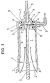
- FIG. 1 One embodiment of this invention is shown in Fig. 1.
- a piercing knife (2) is provided at the end (1') of a tubular main body (1), and its basal part (1") is communicated with a shank (3).
- a hole communicating from inside to outside the main body is disposed at a proper position.
- a casing (5) is provided around the surface of the basal part (1").
- the casing (5) has a hollow part (6) which is opened to the side opposite to the basal part (1").
- the casing (5) also has a tube (7) to communicate with an external vacuum pump (not shown).
- a bearing is installed at the abutting position of the casing (5) and basal part (I") to keep airtight in the hollow part (6) of the casing (5). Furthermore, by this bearing (8), the tubular main body can rotate relatively to the casing (5).
- Numeral (9) is a guide drill for determining the position of piercing.
- the cutting chips in the tubular main body (1) pass through the hole (4) to enter the hollow part (6), and are discharged to outside through the tube (7).
- the position of the hole (4) is not limited to the point indicated in the drawing, but it may be, for example, provided at positions (a), (b), (c), etc. in Fig. 1, and the casing (5) may be provided depending on its position.
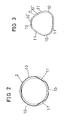
- the piercing knife (2) may be composed of, as shown in Fig. . 2 (an X-X line end section in Fig. 1), a cylindrical part (10) and a flat retreat part (11).
- the cylindrical part (10) and retreat part (11) are disposed at three positions respectively in the illustrated example, but they may be provided at more than or less than three positions, and similar effects are expected. It is for the purpose of keeping a space for allowing the cutting chips going to out side of the piercing knife (2) to escape that the retreat part (11) is provided. Therefore, the retreat part (11) may be disposed at one position, two positions, four positions, five positions, six positions or more.
- a play of about 2 mm is generally required, and it is desired that the knife tip be located on the circle having this width.
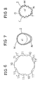
- FIG. 8 A preferred configuration of piercing knives at this time is shown in Fig. 8. This is a schematic drawing showing the position of the tip (2'). If the ellipsoidal part (N) is larger in diameter when rotating than the other round part (M), the knife tip (2") positioned at the maximum diameter portion is arranged so as to trace the track drawn by the outermost diameter of the knife tip (2') disposed in the round part (M) (that is, circle (o)). This is because the largest diameter portion of the piercing knife (2) receives the largest moment by rotation, and it is intended to lessen it to keep the balance of the load applied to the knives.
- knife tip composition is not limited to the one shown in this drawing, but it is effective also in the hole saw described below. (That is, it is intended to compose so that the rotary tracks by the knife tips placed at the largest diameter portion and the smallest diameter portion may be matched as far as possible.)
- a play of about 2 mm is generally required, and it is desired to dispose the knife tips on the circle having this width.
- the play is generally about 2 mm, and the number of knife tips, if the radius of the piercing knife (2) is about 2 or 3 cm, is around 30.
- Fig. 8 is intended to explain the position of the knife, not the number of knives.
- Other embodiment is shown in Fig. 9.
- FIG. 11 The distance from the rotary shaft (x') to the outer periphery of the piercing knife (2), that is, the diameter composes an ellipse, having the smallest part (the minor axis (p')) and largest part (the major axis (q')), and the length varies progressively.
- Fig. 12 This is a schematic drawing showing a referred example of configuration of the piercing knives (2).
- the knife tip (2") (1") disposed near the largest part may be positioned on or near the track (that is, the circle (o')) drawn by the rotation of the knife tip (2')(2') disposed near the smallest part (the minor axis (p') of the ellipse).
- the largest part of the diameter of the piercing knife (2) is subjected to the greatest moment by rotation, and it is intended to lessen it to keep balance of the load applied to the cutting knives.
- a step (p) is formed at one position in the piercing knife (2) by forming the largest part and smallest part in the distance from the rotary shaft (x'), and the other part of the piercing knife (2) gradually changes in the radius (r) from the rotary shaft (x') in one direction (that is, it is composed to keep the relation of (r1) ⁇ (r2) ⁇ ,...(rn) in the drawing).
- This step (p) may not be . limited to one position, but may be formed in two or more positions, and the object of this application may be satisfied as far as the radius (r) of the circumference of the piercing knife (2) between the steps may vary gradually.
- FIG. 14 A further different embodiment is shown in Fig. 14 in a sectional view of piercing knife (2).
- FIG. 15 Another different embodiment is shown in Fig. 15 in a sectional view of piercing knife (2).
- This is formed by combining with a circle of which center is not on the rotary shaft (x').
- Fig. 16 may be also included.
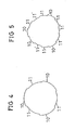
- Fig. 15, Fig. 16 instead of circles, ellipses may be combined. Or circles and ellipses may be combined, relating to Fig. 13, Fig. 14.
- the piercing knife (2) may be formed in an ordinary circular shape in the entire section, and only the vicinity of the knife tip (2') may be deformed according to the illustrated examples in the individual drawings.
- the knife tip (2') is not limited to the shown example, but the tip may be buried or mounted.
- the hole saw of this application is expected to have sufficient effects in piercing of wood, concrete, asphalt, iron, aluminum, stainless steel, other metal and other ALC, and the material of the workpiece is not limited.
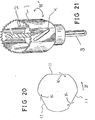
- an end tubular body (50) is composed of an arc portion (4a) and a retreat portion (5b) on a section orthogonal to its axial direction (.the state of mounting the end tubular body (50) on the end insertion part (32) of the body part (B) is shown in Fig. 1).
- the arc portion (5a) has a peripheral ratio nearly same as that of the intended hole diameter.
- the retreat portion (5b) is nearly linear withdrawing in the radial direction as compared with the arc portion (5a). This is only intended to show that the end tubular body (50) is formed detachably on the main body (10), and it is not to define the shape of the end tubular body (50).
- This end tubular body (50) if affixed to the end of the body part (B).
- flange part (31) and insertion part (32) are formed, and the end tubular body (50) is inserted in the insertion part (32) at its basal part, and abuts against the flange part (31).
- the insertion part (31) has an outer circumferential shape corresponding to the inner circumferential shape of the end tubular body (50).
- a detent groove (33) extending in the peripheral direction is formed in the arc portion (32a) of the insertion part (32), while a projection (32) is formed on the inner wall of the arc portion (5a) of the end tubular body (50).
- the flange part (31) possesses an outside diameter nearly equal to that of the end tubular part (5).
- the portion continuous to the retreat portion (32b) of the insertion part (32) has a slope (31b) obliquely cut so as to be continuous smoothly. This slope (31b) is not absolutely necessary.
- the outer circumferential shape of the flange part (31) may be made identical with that of the end tubular body (50).
- the outside diameter of the body part (B) is set smaller than the outside diameter of the flange part (31) so as to keep a space for receiving cutting chips against the inner wall of the hole, but the both (B) and (31) may be designed in the same diameter. n
- the sectional shape of the body is free, and iptead of a circle, it may be adjusted to the sectional shape of the end tubular body, or it may be polygonal, too.
- this hole saw it is possible to pierce while discharging smoothly the cutting chips from the end tubular body, and also to detach the end tubular body from the main body, so that this part only can be replaced.
- the piercing knife (2) and the tubular main body (1) may be composed in one body to make up a hole saw.
- a longitudinal groove (110) or spiral groove (120) may be formed on the end tubular body or also on the surface of the main body. Or, though not shown, the rear end of the end tubular body may be in a circular section as in the prior art.
- the hole (K) at the side of the main body (1) is provided in order to scrape out the chips collected inside the main body (1) by inserting the tip of a screwdriver or the like.
- this hole (K) is formed in the suction type hole saw, for example, as shown in Fig. 1, the cutting chips outside the retreat part (11) may be taken into the main body (11), so that it is effective to discharge.
- the taken-in effect of the cutting chips may be improved.
- a hole (K) is formed obliquely to the rotating direction (Z') of the hole saw, the opening area can be wider, and the effect be greater
- the hole saw of this invention can be applied in piercing of various materials as a rotary cutting tool, and can pierce smoothly.
Landscapes
- Engineering & Computer Science (AREA)
- Mechanical Engineering (AREA)
- Drilling Tools (AREA)
- Processing Of Stones Or Stones Resemblance Materials (AREA)
Priority Applications (1)
| Application Number | Priority Date | Filing Date | Title |
|---|---|---|---|
| AT88900114T ATE89208T1 (de) | 1987-12-18 | 1987-12-18 | Lochsaege. |
Applications Claiming Priority (5)
| Application Number | Priority Date | Filing Date | Title |
|---|---|---|---|
| JP1986195381U JPH0440811Y2 (de) | 1986-12-18 | 1986-12-18 | |
| JP1987044792U JPH039933Y2 (de) | 1987-03-25 | 1987-03-25 | |
| JP1987044791U JPS63151209U (de) | 1987-03-25 | 1987-03-25 | |
| JP1987069089U JPH0618727Y2 (ja) | 1987-05-08 | 1987-05-08 | ホ−ルソ− |
| JP1987162800U JPH071219Y2 (ja) | 1987-10-23 | 1987-10-23 | ホ−ルソ− |
Publications (3)
| Publication Number | Publication Date |
|---|---|
| EP0295309A1 true EP0295309A1 (de) | 1988-12-21 |
| EP0295309A4 EP0295309A4 (de) | 1990-05-14 |
| EP0295309B1 EP0295309B1 (de) | 1993-05-12 |
Family
ID=27522424
Family Applications (1)
| Application Number | Title | Priority Date | Filing Date |
|---|---|---|---|
| EP88900114A Expired - Lifetime EP0295309B1 (de) | 1986-12-18 | 1987-12-18 | Lochsäge |
Country Status (4)
| Country | Link |
|---|---|
| US (1) | US5007777A (de) |
| EP (1) | EP0295309B1 (de) |
| KR (1) | KR950011666B1 (de) |
| WO (1) | WO1988004588A1 (de) |
Cited By (8)
| Publication number | Priority date | Publication date | Assignee | Title |
|---|---|---|---|---|
| EP0739673A1 (de) * | 1995-04-27 | 1996-10-30 | Hawera Probst GmbH + Co. | Bohrkronenrohr |
| WO2011088269A1 (en) | 2010-01-13 | 2011-07-21 | Irwin Industrial Tool Company | Hole cutter with axially- elongated aperture defining multiple fulcrums |
| US9724766B2 (en) | 2010-01-13 | 2017-08-08 | Irwin Industrial Tool Company | Hole cutter with multiple fulcrums |
| US9782839B2 (en) | 2010-01-13 | 2017-10-10 | Irwin Industrial Tool Company | Hole cutter with chip egress aperture |
| US9808869B2 (en) | 2010-01-13 | 2017-11-07 | Irwin Industrial Tool Company | Hole cutter with chip egress aperture |
| US9884374B2 (en) | 2015-09-03 | 2018-02-06 | Irwin Industrial Tool Company | Hole cutter with multiple fulcrums |
| US10137507B2 (en) | 2010-01-13 | 2018-11-27 | Irwin Industrial Tool Company | Hole cutter with multiple fulcrums |
| USD845362S1 (en) | 2017-12-04 | 2019-04-09 | Black & Decker Inc. | Holesaw |
Families Citing this family (26)
| Publication number | Priority date | Publication date | Assignee | Title |
|---|---|---|---|---|
| US5791837A (en) * | 1996-08-16 | 1998-08-11 | Johnson; Samuel | Annular tool for cutting holes in metal |
| AT413420B (de) * | 2002-06-07 | 2006-02-15 | Techmo Entw & Vertriebs Gmbh | Verfahren und anordnung zum raschen verbinden und lösen von miteinander verbindbaren elementen |
| USD478105S1 (en) | 2002-08-02 | 2003-08-05 | South Deerfield Industries, Inc. | Hole saw |
| USD478339S1 (en) | 2002-08-02 | 2003-08-12 | South Deerfield Industries, Inc. | Hole saw |
| USD478919S1 (en) | 2002-08-02 | 2003-08-26 | South Deerfield Industries, Inc. | Hole saw |
| USD478106S1 (en) | 2002-08-02 | 2003-08-05 | South Deerfield Industries, Inc. | Hole saw |
| US20050105981A1 (en) * | 2003-09-26 | 2005-05-19 | The M. K. Morse Company | Hole cutter and method for producing |
| USD516594S1 (en) | 2004-04-30 | 2006-03-07 | Kennametal Inc. | Hole saw |
| WO2009009610A2 (en) * | 2007-07-09 | 2009-01-15 | Brigham Young University | Methods and devices for charged molecule manipulation |
| CA2694726C (en) * | 2007-08-01 | 2015-06-30 | Team Fair Holdings Limited | Hole saw system with improved slug removability |
| US20100310332A1 (en) * | 2009-06-09 | 2010-12-09 | Henry Serba | Quick core removal hole cutting product |
| CA2719726C (en) * | 2009-09-23 | 2013-04-23 | Btt Corporation | Cutting tool |
| AU2010308389B2 (en) * | 2009-10-20 | 2016-02-25 | Smith & Nephew, Inc. | Connector assembly |
| US8579554B2 (en) * | 2010-01-13 | 2013-11-12 | Irwin Industrial Tool Company | Hole cutter with axially-elongated aperture defining multiple fulcrums |
| USD659176S1 (en) | 2010-01-13 | 2012-05-08 | Irwin Industrial Tool Company | Hole saw |
| US8573907B2 (en) | 2010-01-13 | 2013-11-05 | Irwin Industrial Tool Company | Hole cutter with minimum tooth pitch to blade body thickness ratio |
| USD690334S1 (en) | 2010-01-13 | 2013-09-24 | Irwin Industrial Tool Company | Hole saw |
| WO2014015154A1 (en) | 2012-07-18 | 2014-01-23 | Milwaukee Electric Tool Corporation | Hole saw |
| EP2745965A1 (de) * | 2012-12-21 | 2014-06-25 | HILTI Aktiengesellschaft | Bohrkrone mit einem austauschbaren Schneidabschnitt |
| EP2745966A1 (de) * | 2012-12-21 | 2014-06-25 | HILTI Aktiengesellschaft | Bohrkrone mit einem austauschbaren Schneidabschnitt |
| EP2886230A1 (de) * | 2013-12-20 | 2015-06-24 | HILTI Aktiengesellschaft | Bohrkrone mit einem austauschbaren Schneidabschnitt |
| JP2018043327A (ja) * | 2016-09-16 | 2018-03-22 | 株式会社ミヤナガ | コアドリル |
| CN216028284U (zh) | 2018-07-10 | 2022-03-15 | 米沃奇电动工具公司 | 孔锯 |
| EP3986650A4 (de) | 2019-06-20 | 2023-07-19 | Milwaukee Electric Tool Corporation | Lochsäge mit kreisförmigen seitenwandöffnungen |
| USD958855S1 (en) | 2019-12-09 | 2022-07-26 | Milwaukee Electric Tool Corporation | Hole saw |
| AT526727B1 (de) * | 2022-11-17 | 2025-06-15 | Tyrolit Schleifmittelwerke Swarovski Ag & Co K G | Anordnung aus wenigstens einer Bohrkrone und wenigstens einem Anschlag |
Family Cites Families (17)
| Publication number | Priority date | Publication date | Assignee | Title |
|---|---|---|---|---|
| US1829659A (en) * | 1931-06-22 | 1931-10-27 | Albert F Kefflo | Tubular saw |
| US2179029A (en) * | 1938-11-02 | 1939-11-07 | Barnes Ernest | Boring tool |
| US2349400A (en) * | 1942-01-21 | 1944-05-23 | Milwaukee Electric Tool Corp | Saw |
| US2794469A (en) * | 1954-01-11 | 1957-06-04 | Millers Falls Co | Hole saws |
| US2779361A (en) * | 1954-03-17 | 1957-01-29 | Miller Mfg Corp | Sawing tool for cutting circular holes |
| US3382743A (en) * | 1965-12-08 | 1968-05-14 | Walter Trevathan Corp | Drilling machine bit means |
| US3495359A (en) * | 1968-10-10 | 1970-02-17 | Norton Co | Core drill |
| GB1242829A (en) * | 1970-07-06 | 1971-08-11 | Uk Ni K T I Sint Sverkhtverdyk | Tubular diamond drill |
| SU538824A1 (ru) * | 1973-07-02 | 1976-12-15 | Резцова головка | |
| DE2549731A1 (de) * | 1975-11-06 | 1977-05-12 | Hans Heinlein | Werkzeug, insbesondere zum bohren und bearbeiten von durchgangsbohrungen grossen durchmessers |
| DE2602238A1 (de) * | 1976-01-22 | 1977-08-04 | Bosch Gmbh Robert | Bohrkrone |
| DE2948682A1 (de) * | 1979-12-04 | 1981-06-11 | Friedrich Duss Maschinenfabrik GmbH & Co, 7265 Neubulach | Von hand fuehrbares bohr- oder schlagbohrgeraet mit absaugvorrichtung |
| DE8406278U1 (de) * | 1984-02-29 | 1984-05-30 | Hawera Probst Gmbh + Co, 7980 Ravensburg | Adapter mit drehbohrkrone |
| JPS61148607U (de) * | 1985-03-04 | 1986-09-13 | ||
| DE3541477C2 (de) * | 1985-08-24 | 1993-10-28 | Kaiser Gmbh & Co Kg | Bohrwerkzeug zum Herstellen von Wandausnehmungen |
| JPH0516317Y2 (de) * | 1988-01-11 | 1993-04-28 | ||
| JPH0542391U (ja) * | 1991-11-06 | 1993-06-08 | タキロン株式会社 | コンクリート構造物のライニング構造 |
-
1987
- 1987-12-18 US US07/251,221 patent/US5007777A/en not_active Expired - Fee Related
- 1987-12-18 WO PCT/JP1987/000992 patent/WO1988004588A1/ja not_active Ceased
- 1987-12-18 KR KR1019880700991A patent/KR950011666B1/ko not_active Expired - Fee Related
- 1987-12-18 EP EP88900114A patent/EP0295309B1/de not_active Expired - Lifetime
Cited By (20)
| Publication number | Priority date | Publication date | Assignee | Title |
|---|---|---|---|---|
| EP0739673A1 (de) * | 1995-04-27 | 1996-10-30 | Hawera Probst GmbH + Co. | Bohrkronenrohr |
| US5676501A (en) * | 1995-04-27 | 1997-10-14 | Hawera Probst Gmbh | Drill bit tube |
| US10137507B2 (en) | 2010-01-13 | 2018-11-27 | Irwin Industrial Tool Company | Hole cutter with multiple fulcrums |
| US10549356B2 (en) | 2010-01-13 | 2020-02-04 | Black & Decker Inc. | Hole cutter with multiple fulcrums |
| US9724766B2 (en) | 2010-01-13 | 2017-08-08 | Irwin Industrial Tool Company | Hole cutter with multiple fulcrums |
| US20170232530A1 (en) | 2010-01-13 | 2017-08-17 | Irwin Industrial Tool Company | Hole cutter with multiple fulcrums |
| US9782839B2 (en) | 2010-01-13 | 2017-10-10 | Irwin Industrial Tool Company | Hole cutter with chip egress aperture |
| US9808869B2 (en) | 2010-01-13 | 2017-11-07 | Irwin Industrial Tool Company | Hole cutter with chip egress aperture |
| US12036617B2 (en) | 2010-01-13 | 2024-07-16 | Black & Decker Inc. | Hole cutter with multiple fulcrums |
| US20180272441A1 (en) | 2010-01-13 | 2018-09-27 | Irwin Industrial Tool Company | Hole cutter with multiple fulcrums |
| WO2011088269A1 (en) | 2010-01-13 | 2011-07-21 | Irwin Industrial Tool Company | Hole cutter with axially- elongated aperture defining multiple fulcrums |
| US11103934B2 (en) | 2010-01-13 | 2021-08-31 | Black & Decker Inc. | Hole cutter with multiple fulcrums |
| US10259051B2 (en) | 2010-01-13 | 2019-04-16 | Black & Decker, Inc. | Hole cutter with chip egress aperture |
| US10500651B2 (en) | 2010-01-13 | 2019-12-10 | Black & Decker Inc. | Hole cutter with multiple fulcrums |
| US10500652B2 (en) | 2010-01-13 | 2019-12-10 | Black & Decker Inc. | Hole cutter with multiple fulcrums |
| EP2523771A4 (de) * | 2010-01-13 | 2014-04-16 | Irwin Ind Tool Co | Lochschneider mit axial verlängerter öffnung zur definition mehrerer drehpunkte |
| EP3608046A1 (de) * | 2010-01-13 | 2020-02-12 | Black & Decker Inc. | Lochschneider mit axial verlängerter öffnung zur definition mehrerer drehpunkte |
| US10835967B2 (en) | 2010-01-13 | 2020-11-17 | Black & Decker Inc. | Hole cutter with chip egress aperture |
| US9884374B2 (en) | 2015-09-03 | 2018-02-06 | Irwin Industrial Tool Company | Hole cutter with multiple fulcrums |
| USD845362S1 (en) | 2017-12-04 | 2019-04-09 | Black & Decker Inc. | Holesaw |
Also Published As
| Publication number | Publication date |
|---|---|
| KR890700056A (ko) | 1989-03-02 |
| EP0295309A4 (de) | 1990-05-14 |
| EP0295309B1 (de) | 1993-05-12 |
| US5007777A (en) | 1991-04-16 |
| WO1988004588A1 (fr) | 1988-06-30 |
| KR950011666B1 (ko) | 1995-10-07 |
Similar Documents
| Publication | Publication Date | Title |
|---|---|---|
| EP0295309A1 (de) | Lochsäge | |
| US4408935A (en) | Metal borer | |
| US4134706A (en) | Axially supported boring tool | |
| US5137098A (en) | Diamond tool for drilling and routing | |
| US6120220A (en) | Rotary cutting tool | |
| JP2004507373A (ja) | ドリルなどの回転式切削工具 | |
| US20080008548A1 (en) | Hole saw with replaceable cutting tip | |
| US8070397B2 (en) | Self feed bit | |
| US4352610A (en) | Method and tool for generating holes in composite materials | |
| JP5230201B2 (ja) | きりもみ・さらもみ工具用のドリルときりもみ・さらもみ工具 | |
| US11446743B2 (en) | Side-lock modular drill with spring-assisted bump-off | |
| JP2002120220A (ja) | 削岩ドリル | |
| JP2000107919A (ja) | ホールソーおよび孔開け工具 | |
| WO2009128183A1 (ja) | 深穴切削用ドリルヘッド | |
| KR870000760B1 (ko) | 링형커터 | |
| US5980169A (en) | Brad point drill bit | |
| EP0089123A1 (de) | Bohrer für Bohrungen mit flachem Grund | |
| JPH0615512A (ja) | ドリルおよびドリルの切刃形成方法 | |
| KR840001089B1 (ko) | 드 릴 | |
| JPH0440811Y2 (de) | ||
| JP2552135Y2 (ja) | リングビット | |
| JP3835052B2 (ja) | 転削工具 | |
| JPH039933Y2 (de) | ||
| KR200226443Y1 (ko) | 중심고정날이 구비된 코어드릴 | |
| JP4344061B2 (ja) | 切削工具 |
Legal Events
| Date | Code | Title | Description |
|---|---|---|---|
| PUAI | Public reference made under article 153(3) epc to a published international application that has entered the european phase |
Free format text: ORIGINAL CODE: 0009012 |
|
| AK | Designated contracting states |
Kind code of ref document: A1 Designated state(s): AT BE CH DE FR GB IT LI LU NL SE |
|
| 17P | Request for examination filed |
Effective date: 19881228 |
|
| A4 | Supplementary search report drawn up and despatched |
Effective date: 19900514 |
|
| 17Q | First examination report despatched |
Effective date: 19910710 |
|
| GRAA | (expected) grant |
Free format text: ORIGINAL CODE: 0009210 |
|
| AK | Designated contracting states |
Kind code of ref document: B1 Designated state(s): AT BE CH DE FR GB IT LI LU NL SE |
|
| PG25 | Lapsed in a contracting state [announced via postgrant information from national office to epo] |
Ref country code: IT Free format text: LAPSE BECAUSE OF FAILURE TO SUBMIT A TRANSLATION OF THE DESCRIPTION OR TO PAY THE FEE WITHIN THE PRE;WARNING: LAPSES OF ITALIAN PATENTS WITH EFFECTIVE DATE BEFORE 2007 MAY HAVE OCCURRED AT ANY TIME BEFORE 2007. THE CORRECT EFFECTIVE DATE MAY BE DIFFERENT FROM THE ONE RECORDED.SCRIBED TIME-LIMIT Effective date: 19930512 Ref country code: BE Effective date: 19930512 Ref country code: CH Effective date: 19930512 Ref country code: LI Effective date: 19930512 Ref country code: AT Effective date: 19930512 Ref country code: FR Effective date: 19930512 Ref country code: NL Effective date: 19930512 Ref country code: SE Effective date: 19930512 |
|
| REF | Corresponds to: |
Ref document number: 89208 Country of ref document: AT Date of ref document: 19930515 Kind code of ref document: T |
|
| REF | Corresponds to: |
Ref document number: 3785850 Country of ref document: DE Date of ref document: 19930617 |
|
| RAP2 | Party data changed (patent owner data changed or rights of a patent transferred) |
Owner name: YAMAMOTO, HIROYUKI |
|
| REG | Reference to a national code |
Ref country code: CH Ref legal event code: PL |
|
| EN | Fr: translation not filed | ||
| NLV1 | Nl: lapsed or annulled due to failure to fulfill the requirements of art. 29p and 29m of the patents act | ||
| PG25 | Lapsed in a contracting state [announced via postgrant information from national office to epo] |
Ref country code: LU Free format text: LAPSE BECAUSE OF NON-PAYMENT OF DUE FEES Effective date: 19931231 |
|
| PGFP | Annual fee paid to national office [announced via postgrant information from national office to epo] |
Ref country code: GB Payment date: 19961209 Year of fee payment: 10 |
|
| PGFP | Annual fee paid to national office [announced via postgrant information from national office to epo] |
Ref country code: DE Payment date: 19961231 Year of fee payment: 10 |
|
| PG25 | Lapsed in a contracting state [announced via postgrant information from national office to epo] |
Ref country code: GB Free format text: LAPSE BECAUSE OF NON-PAYMENT OF DUE FEES Effective date: 19971218 |
|
| GBPC | Gb: european patent ceased through non-payment of renewal fee |
Effective date: 19971218 |
|
| PG25 | Lapsed in a contracting state [announced via postgrant information from national office to epo] |
Ref country code: DE Free format text: LAPSE BECAUSE OF NON-PAYMENT OF DUE FEES Effective date: 19980901 |
|
| PLBE | No opposition filed within time limit |
Free format text: ORIGINAL CODE: 0009261 |
|
| STAA | Information on the status of an ep patent application or granted ep patent |
Free format text: STATUS: NO OPPOSITION FILED WITHIN TIME LIMIT |