EP0295372A1 - Butée avant pour fixation de sécurité pour ski déclenchable latéralement - Google Patents
Butée avant pour fixation de sécurité pour ski déclenchable latéralement Download PDFInfo
- Publication number
- EP0295372A1 EP0295372A1 EP88104782A EP88104782A EP0295372A1 EP 0295372 A1 EP0295372 A1 EP 0295372A1 EP 88104782 A EP88104782 A EP 88104782A EP 88104782 A EP88104782 A EP 88104782A EP 0295372 A1 EP0295372 A1 EP 0295372A1
- Authority
- EP
- European Patent Office
- Prior art keywords
- sole
- sole holder
- ski boot
- force
- ski
- Prior art date
- Legal status (The legal status is an assumption and is not a legal conclusion. Google has not performed a legal analysis and makes no representation as to the accuracy of the status listed.)
- Granted
Links
Images

Classifications
-
- A—HUMAN NECESSITIES
- A63—SPORTS; GAMES; AMUSEMENTS
- A63C—SKATES; SKIS; ROLLER SKATES; DESIGN OR LAYOUT OF COURTS, RINKS OR THE LIKE
- A63C9/00—Ski bindings
- A63C9/001—Anti-friction devices
-
- A—HUMAN NECESSITIES
- A63—SPORTS; GAMES; AMUSEMENTS
- A63C—SKATES; SKIS; ROLLER SKATES; DESIGN OR LAYOUT OF COURTS, RINKS OR THE LIKE
- A63C9/00—Ski bindings
- A63C9/08—Ski bindings yieldable or self-releasing in the event of an accident, i.e. safety bindings
- A63C9/085—Ski bindings yieldable or self-releasing in the event of an accident, i.e. safety bindings with sole hold-downs, e.g. swingable
- A63C9/08507—Ski bindings yieldable or self-releasing in the event of an accident, i.e. safety bindings with sole hold-downs, e.g. swingable with a plurality of mobile jaws
- A63C9/08521—Ski bindings yieldable or self-releasing in the event of an accident, i.e. safety bindings with sole hold-downs, e.g. swingable with a plurality of mobile jaws pivoting about a vertical axis, e.g. side release
-
- A—HUMAN NECESSITIES
- A63—SPORTS; GAMES; AMUSEMENTS
- A63C—SKATES; SKIS; ROLLER SKATES; DESIGN OR LAYOUT OF COURTS, RINKS OR THE LIKE
- A63C9/00—Ski bindings
- A63C9/08—Ski bindings yieldable or self-releasing in the event of an accident, i.e. safety bindings
- A63C9/085—Ski bindings yieldable or self-releasing in the event of an accident, i.e. safety bindings with sole hold-downs, e.g. swingable
- A63C9/08557—Details of the release mechanism
- A63C9/08564—Details of the release mechanism using cam or slide surface
Definitions
- the invention relates to a side-releasable cheek, in particular a toe, a safety ski binding according to the preamble of patent claim 1.
- a release front jaw for ski bindings is already known (AT-PS 300 630), in which a sole hold-down device is arranged on a side release front jaw, which can deflect resiliently upwards against the bias of a spring. This is to prevent e.g. in the case of an intermediate layer of snow between the shoe and the ski, the shoe exerts abnormal stresses on the binding and the ski and thus changes the functional properties of the binding.
- a disadvantage of this known ski binding is the need for a special hold-down spring.
- the sole hold-down device, the side jaws, the side release mechanism and the point of application of the release spring on the side release mechanism are arranged on a support part which can be swiveled up about a transverse axis relative to the binding housing, and that the transverse axis is in one such a distance above the line of action of the trigger spring, the one from the top of the trigger spring-originating, predetermined, resilient hold-down force acts on the ski boot sole.
- the trigger spring generates a torque about the transverse axis, which attempts to move the sole hold-down device downwards.
- This design not only avoids the disadvantages associated with a layer of snow between the sole of the shoe and the ski, in particular jamming of the sole of the shoe, but it also already achieves limited friction compensation. If the skier gets into a position of rest, the friction on the sole hold-down becomes somewhat increased, but at the same time the friction on the sole plate decreases greatly, so that the side release is not difficult, but rather easier, which is quite desirable in the event of a backward fall.
- a disadvantage of this known safety ski binding is that a housing which can be swiveled up about a transverse axis must be provided, which entails an increased production outlay.
- the aim of the invention is to develop a side-releasable jaw with a sole holder which can be swiveled out laterally about tilting axes, as is known, for example, from DE-PS 31 29 536, in such a way that, with little increased construction effort, the ski boot sole is clamped too tightly between them Hold-down of the sole holder and the ski surface or a step plate arranged thereon is avoided and a certain relief of the lateral release process is achieved when the skier is lying back.
- the basic idea of the invention is therefore to additionally utilize the tilting surfaces or tilting edges already required for the side release as up and down sliding surfaces for the sole holder, for which purpose only one ge Know displacement space for the sole holder and for the triggering force transmission elements acting on it and the angle defined in claim 1 between the tilt axes and the line of action of the trigger spring must be provided.
- the sole holder When a slightly thicker boot sole is inserted, the sole holder is pushed up a little along the tilt axes, while when a thinner shoe sole is subsequently inserted, the downward force component of the release spring pushes the sole holder down along the tilt axis until the hold-down device pushes against the sole of the Ski boot is lightly pressed.
- the ski boot sole is thus clamped between the tread plate on the ski surface and the hold-down device of the sole holder, the vertical tension force being supplied by the release spring. It is essential that there is such a free space in front of the tread plate under the hold-down of the sole holder that any ski boot sole can be inserted obliquely from above under the hold-down.
- the sole of the shoe can shift the sole holder somewhat upwards along the tilting axes.
- the sole of the shoe lifts off the ski surface or the step plate, so that the lateral friction which is otherwise present there is eliminated and the lateral release process is facilitated in the desired manner.
- the angle between the release spring line of action and the tilt axes can be practically implemented by the measures of claims 2 or 3, whereby in order to avoid an excessive inclination of the line of action of the release spring and the tilt axes, both measures are expediently combined in such a way that they are approximately the same contribute to the desired effect.
- a particularly expedient dimensioning of the aforementioned angle is defined by claim 4.
- the inventive design of the display extension according to claim 7 has the particular advantage that when setting a somewhat thicker shoe sole in the cheeks, which results in a stronger bias of the release spring, the display extension is also moved, so that by adjusting the thicker The sole of the shoe is caused by greater trigger hardness. By adjusting the preload of the release spring, the desired release value can be set again.
- the release spring acts on the sole holder according to the features of patent claim 9.
- the pivot shaft can be rotated relative to the sole holder, which in a simple manner enables relative rotation between the spring end engaging the sole holder and the sole holder.
- the measure according to claim 10 is provided.
- a particularly advantageous development of the invention is characterized by claim 12.
- a height release of the jaw is also guaranteed in addition to the side release.
- the only structural measures for this consist in the suitable arrangement of the height-tilt stop as well as the height-tilt counter surfaces and the free spaces in between.
- a tread plate according to claim 15 should be provided in the baking according to the invention.
- friction compensation can also be achieved when the skier is presented with an increased pressure from above on the tread plate in that the hold-down device of the sole holder is then lifted off the top of the sole , whereby the friction that is otherwise present there is made to disappear when the side is triggered.
- the friction compensation is not achieved by partial compensation of the release force, but rather only by pushing up the sole holder on the tilting surfaces.
- tread plate is characterized by claims 18 and 19.
- This embodiment can also be used independently of the jaws according to the invention, but should only be used in the case of side-releasable jaws in which, after the lateral displacement area of the tread plate has been exhausted, the restoring force acting on the jaws has already dropped to such an extent that the sum of the remaining restoring force and the friction force is significantly less than the Aösöswert.
- the step plate designed in this way offers triple security for the skier.
- the low-friction covering which is preferably made of Teflon, ensures security in the event that the sideways displacement of the tread plate due to freezing or corrosion should be eliminated. Then there is the comparatively low friction between the low-friction covering and the shoe sole.
- the emergency tread surface still offers the necessary low-friction support. It is of particular importance that the emergency tread surface does not have to be made of a very abrasion-resistant, low-friction material, because it is normally not used and only has to perform its function for a relatively short time if the laterally displaceable tread plate is lost.
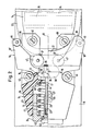
- a binding housing 11 is fastened to the surface of a ski 15 by means of screws 40, which on the side facing away from the ski boot 14 has an approximately cylindrical recess 41 running essentially in the longitudinal direction of the ski for receiving a release spring 12.
- the trigger spring 12 is supported on the shoe side on a radially inwardly projecting ring abutment 11 'and extends from there obliquely downwards and forwards into a hollow cylindrical, shell-like abutment 24, which can slide axially within the recess 41 like a piston.
- the abutment 24 has an axial display extension 25, the end of which faces the ski boot 14 is arranged below a window 27 provided with a release hardness scale 26 in the upper side of the binding housing 11.
- pull rod 23 In a central bore 42 in the front bottom of the abutment 24 one with a e.g. by a screwdriver rotatable head 43 provided pull rod 23 coaxial with the release spring 12.
- the pull rod 23 consists of a part connected to the head 43 and having an axial threaded bore 23 ⁇ , in which a second, designed as a threaded rod from the side of the ski boot 14 Part 23 'is screwed in.
- the part 23 ' extends through an opening 44 within the abutment 11' with clear play on all sides to a slightly forward-tilted, but essentially vertical pivot shaft 28, which is encompassed by means of a bore 45 in the end of part 23 ', namely in the region of an annular recess which has a conical inclined surface 29.
- the cone angle on the side of the relevant recess facing the ski boot 14 corresponds to the angle between the axis of the pull rod 23, i.e. the line of action 19 of the release spring 12 and the axis of the pivot shaft 28. In this way, the force of the release spring 12 acts perpendicularly on the inclined surface 29.
- the two halves 18 ', 18' of a sole holder 18 are articulated on the pivot shaft 28 which cannot be rotated relative to the pull rod 23.
- the two sole holder halves 18 ', 18' each extend beyond the vertical central longitudinal plane 13 and protrusions 30 ', 30' which are vertically offset in the manner shown in FIG. 1 and are in rotational engagement with the pivot shaft 23 .
- the sole holder 18 In the vertical direction, the sole holder 18 is fixed relative to the pivot shaft 28, that is to say cannot be displaced.
- tilting axes 16 are provided which are essentially upright and which are of the same design and are substantially upright on the ski surface are symmetrical to the central longitudinal plane 13. With these tilting surfaces, complementary tilting counter-surfaces 17 of the two halves 18 ', 18 ⁇ of the sole holder 18 act together through the release spring 12.
- the sole holder On the sole holder there is a hold-down device 21 resting on the sole 22 of the ski boot 14 from above; in addition, the sole holder has two lateral legs, on which lateral rollers 46 are arranged, which define lateral support points 38 for the shoe sole 22.
- the support points 38 are located in the areas of the side of the ski boot sole 22 where the sole 22 tapers forward.
- front support rollers 47 which define front support points 37 for the sole 22 of the ski boot.
- the sole holder 18 is arranged with its front regions in a free space 48 of the binding housing 11 in such a way that it can be displaced in relation to the tilting axes 16 in the vertical direction within such a range that all occurring different thicknesses of the sole 22 can be clamped in by the sole holder 18 .
- the pull rod 23 has a corresponding vertical clearance within the opening 44 of the abutment 11 '. Also, the head 43 within the abutment 24 must have a corresponding range of motion.
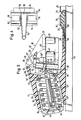
- the free space 48 is closed off by a height-tilting stop 31 which is firmly connected to the binding housing 11 and below which there is an essentially horizontal height-tilting counter surface 32 of the sole holder 18.
- a slide 33 arranged on the upper side of the sole holder 18 can be pushed over this countertop surface 32, the upper surface of which is a slightly higher second one Height tilt counter surface 32 'defined. If the lower countertop surface 32 is to take effect, the slide 33 is in the position shown in FIG. 1, in which it protrudes outwards from the shoe-side surface of the sole holder 18, so that from there in the direction of the arrow in FIG. 1 can be actuated in order to then reach the position shown in dashed lines in Fig.
- a tread plate 34 provided with a low-friction covering 35, which acts on a wedge surface 50, 50 'arranged below it on a wedge 36' which can be displaced in the longitudinal direction of the ski and which can be displaced in the longitudinal direction of the ski, just above the ski surface
- Push rod 36 ⁇ acts on a pivotable lever 36 strigos 51.
- the substantially vertically downward arm of the angle lever 36 ′′′ is acted upon by the push rod 36 ⁇ in the longitudinal direction of the ski.
- the other, essentially horizontal arm of the angle lever 36 ′′′ engages the pivot shaft 28 from below.
- the vertically downward force component N tries to pull the sole holder 18 downwards along the tilting surfaces 20 (FIG. 2).
- the tilting surfaces 17, 20 expediently consist of low-friction material, so that the force component N can overcome the friction between the tilting surfaces 17, 20.
- the sole holder 18 is in its lowermost position, which can be determined, for example, by a stop 51 'arranged under the sole holder.
- the front region of the sole 22 is inserted obliquely from above into the gap between the hold-down device 21 and the tread plate 34, the free space 52 below the hold-down device 21 ensuring that the ski boot can be introduced in this way without excessive resistance such that the sole 22 can be inserted under the holding-down device 21 until it abuts the front support rollers 47.
- the side edges of the sole 22 put on the lateral support rollers 46 and spread the two halves 18 ', 18' of the sole holder 18 just enough that the front surface of the sole 22 comes into contact with the front support rollers 47.
- the heel of the ski boot 14, not shown, is then lowered, whereupon the sole 22 comes to rest with its underside on the tread plate 34 and the upper front edge of the sole 22 raises the hold-down 21 as far as necessary, the sole holder 18 as a whole along the Tilt axis 16 slides slightly upwards.
- the sole 22 of the ski boot 14 is clamped like pliers between the hold-down device 21 and the tread plate 34, the force of the pliers being supplied by the force component N, which comes from the release spring 12.
- the side can now be triggered, as is customary with such a tilting jaw, by pivoting about one of the tilting axes 16.
- the triggering force is determined by the force component A.
- the sole 22 can move the sole holder 18 upward via the hold-down device 21, the pressure from the sole 22 on the tread plate 34 being released.
- the sole holder 18 can pivot upward about a transverse axis present at the end stop 31 and release the ski boot 14.
- the shoe sole 22 presses in the direction of arrow f onto the tread plate 34, whereby the push rod 36 'is pushed forward over the wedge surfaces 50, 50' and the wedge 36 '.
- the pressure of the hold-down 21 disappears from above onto the sole 22, so that the friction normally present there is also eliminated and the friction between the sole 22 and the covering 35 of the tread plate 34 is still present. This ensures a constant or even reduced side release force, so that in the case of a combined forward turn, the side release of the binding is preferably facilitated.
- the Hold-down device 21 In order to keep the friction between the hold-down 21 and the top of the sole 22 low, is below the Hold-down device 21 also has a friction-reducing covering 53, preferably made of Teflon.
- FIG. 3 The structure and function of the embodiment according to FIG. 3 are the same as in the embodiment according to FIGS. 1, 2, except for the friction compensator with the power deflection gear 36 ', 36 ⁇ , 36 ′′′.
- the tread plate 34 ' is mounted on the ski surface so as to be displaceable in a guide 54.
- a spreading spring 56 attached below a cover plate 55 on the surface of the ski in the longitudinal direction of the ski through a limited slot opening 57 into a lower recess 58 of the tread plate 34 ', which, however, can be seen laterally by stops 59 in FIG. 4 Way is limited. Since the safety pin-shaped spreading spring 56 in the rest position shown in FIG. 4 rests on the edges of the slot 57 and at the same time on the side stops 59 of the tread plate 34 ', the tread plate 34' is in a stable means position. However, it can be moved on both sides against the relatively low restoring forces of the spreading spring 56 within the range of motion of the spreading spring 56.
- the lateral displacement area of the tread plate 34 ' is dimensioned such that in the event of a side release, the end of the displacement area of the tread plate 34' is only reached when the restoring force exerted on the sole holder 18 by the release spring 12 has already dropped to such an extent that the sum of the remaining ones Restoring force and the friction between the shoe sole 22 and the low-friction covering 35 is significantly less than the triggering force. In this way, the effects of friction between the sole 22 and the tread plate 34 'in the critical region of the side release are negligible.
- an emergency tread surface 39 is provided behind the tread plate 34 ', the surface of which is somewhat lower than the surface of the low-friction covering 35. If the tread plate 34' spurs out of its guide 54 and is lost, then the emergency tread surface 39 is then also used to support the shoe sole 22 available. The slight difference in height between the covering 35 and the emergency tread surface 39 is easily compensated for by the forceps effect of the baking according to the invention.
- the guide 34 suitably consists of sheet metal, whereby a low coefficient of friction between the plastic foot plate 34 'and the guide 54 is achieved.
- the tread plate 34 'clamps in the guide 54 by freezing or corrosion or also by mechanical damage to the guide 54, the resistance to a lateral movement of the sole 22 remains low because the low-friction coating 35 is provided.
- the lateral range of movement of the tread plate to one side is approximately 15 mm.
- the resistance to a further sideways movement of the sole 22 is then determined by the friction between the sole 22 and the covering 35.
Landscapes
- Footwear And Its Accessory, Manufacturing Method And Apparatuses (AREA)
Priority Applications (1)
| Application Number | Priority Date | Filing Date | Title |
|---|---|---|---|
| AT88104782T ATE65705T1 (de) | 1987-06-19 | 1988-03-24 | Seitenloesbarer vorderbacken einer sicherheitsskibindung. |
Applications Claiming Priority (2)
| Application Number | Priority Date | Filing Date | Title |
|---|---|---|---|
| DE3720440 | 1987-06-19 | ||
| DE19873720440 DE3720440A1 (de) | 1987-06-19 | 1987-06-19 | Seitenausloesbarer vorderbacken einer sicherheitsskibindung |
Publications (2)
| Publication Number | Publication Date |
|---|---|
| EP0295372A1 true EP0295372A1 (fr) | 1988-12-21 |
| EP0295372B1 EP0295372B1 (fr) | 1991-07-31 |
Family
ID=6329985
Family Applications (1)
| Application Number | Title | Priority Date | Filing Date |
|---|---|---|---|
| EP88104782A Expired - Lifetime EP0295372B1 (fr) | 1987-06-19 | 1988-03-24 | Butée avant pour fixation de sécurité pour ski déclenchable latéralement |
Country Status (6)
| Country | Link |
|---|---|
| US (1) | US4889359A (fr) |
| EP (1) | EP0295372B1 (fr) |
| JP (1) | JP2907838B2 (fr) |
| AT (1) | ATE65705T1 (fr) |
| CA (1) | CA1306763C (fr) |
| DE (2) | DE3720440A1 (fr) |
Cited By (6)
| Publication number | Priority date | Publication date | Assignee | Title |
|---|---|---|---|---|
| EP0474020A3 (en) * | 1990-09-04 | 1992-08-05 | Geze Sport International Gmbh | Security ski binding with horizontally swingable sole hold-forms |
| EP0856337A1 (fr) | 1997-01-29 | 1998-08-05 | Look Fixations S.A. | Fixation de sécurité à prise sur tige |
| FR2759603A1 (fr) * | 1997-02-20 | 1998-08-21 | Look Fixations Sa | Fixation de securite de l'extremite avant d'une chaussure |
| FR2764201A1 (fr) | 1997-06-06 | 1998-12-11 | Look Fixations Sa | Dispositif elastique de rappel pour fixation de ski |
| FR2764202A1 (fr) | 1997-06-06 | 1998-12-11 | Look Fixations Sa | Fixation de securite d'une chaussure de ski |
| FR2786706A1 (fr) | 1998-12-08 | 2000-06-09 | Look Fixations Sa | Fixation de ski |
Families Citing this family (17)
| Publication number | Priority date | Publication date | Assignee | Title |
|---|---|---|---|---|
| DE3742483C2 (de) * | 1987-12-15 | 1994-07-07 | Geze Sport | Vorderbacken einer Sicherheitsskibindung |
| ATE97588T1 (de) * | 1988-07-28 | 1993-12-15 | Geze Sport | Seitenausloesbarer vorderbacken einer sicherheitsskibindung. |
| AT390889B (de) * | 1988-10-07 | 1990-07-10 | Tyrolia Freizeitgeraete | Vorderbacken |
| DE4008677A1 (de) * | 1990-03-17 | 1991-09-19 | Geze Sport | Lagervorrichtung zur seitwaerts beweglichen vertikalen abstuetzung eines skischuhes auf einem ski |
| US5449192A (en) * | 1990-09-12 | 1995-09-12 | Salomon S. A. | Boot support plate for ski binding |
| AT395823B (de) * | 1991-03-28 | 1993-03-25 | Tyrolia Freizeitgeraete | Vorrichtung fuer einen skibindungsteil |
| JP2962861B2 (ja) * | 1991-05-20 | 1999-10-12 | キヤノン株式会社 | 振動波モータ |
| AT399663B (de) * | 1992-12-21 | 1995-06-26 | Tyrolia Freizeitgeraete | Vorderbacken für eine sicherheitsbindung |
| AT402696B (de) * | 1993-10-29 | 1997-07-25 | Tyrolia Freizeitgeraete | Vorderbacken für eine sicherheitsskibindung |
| DE9401309U1 (de) * | 1994-01-26 | 1995-06-01 | Marker Deutschland Gmbh, 82438 Eschenlohe | Vorderbacken einer Skibindung |
| US5671942A (en) * | 1994-02-23 | 1997-09-30 | Marker Deutschland Gmbh | Front jaw for a ski binding |
| FR2717705B1 (fr) * | 1994-03-24 | 1996-06-07 | Frederic Paradis | Butée avant pour fixation de sécurité de ski alpin. |
| FR2769236B1 (fr) * | 1997-10-03 | 2000-02-04 | Salomon Sa | Cale d'amortissement pour dispositif de retenue d'une chaussure sur une planche de glisse destinee a la pratique du surf sur neige, et dispositif muni d'une telle cale |
| CH693129A5 (de) | 1998-11-16 | 2003-03-14 | Look Fixations Sa | Sicherheitsskibindung. |
| FR2803533B1 (fr) * | 2000-01-07 | 2002-04-05 | Look Fixations Sa | Dispositif d'appui pour l'avant d'une chaussure de ski sur un ski |
| ITTV20010150A1 (it) * | 2001-11-13 | 2003-05-13 | Benetton Spa | Dispositivo di visualizzazione della posizione di un componente particolarmente per una talloniera e/o un puntale di un attacco di sci |
| DE102013201727A1 (de) * | 2013-02-01 | 2014-08-07 | Marker Deutschland Gmbh | Fersenhalter mit rollenförmigem Sohlenhalter |
Citations (3)
| Publication number | Priority date | Publication date | Assignee | Title |
|---|---|---|---|---|
| US4337965A (en) * | 1975-12-11 | 1982-07-06 | S. A. Des Etablissements Francois Salomon & Fils | Safety binding adapted to be mounted on a ski |
| DE3230186A1 (de) * | 1982-08-13 | 1984-02-16 | Geze Gmbh, 7250 Leonberg | Seitenausloesbarer vorderbacken einer skibindung |
| FR2537442A1 (fr) * | 1982-12-13 | 1984-06-15 | Salomon & Fils F | Fixation de securite pour ski |
Family Cites Families (12)
| Publication number | Priority date | Publication date | Assignee | Title |
|---|---|---|---|---|
| US447826A (en) * | 1891-03-10 | Electric switch and cut-out | ||
| FR1603205A (fr) * | 1968-09-06 | 1971-03-22 | ||
| US4027897A (en) * | 1975-11-25 | 1977-06-07 | Kurt Hildebrand | Safety ski binding |
| DE2608073C3 (de) * | 1976-02-27 | 1981-01-29 | Marker, Hannes, 8100 Garmisch-Partenkirchen | Fersenniederhalter für Sicherheits-Skibindungen |
| AT363363B (de) * | 1979-09-19 | 1981-07-27 | Tyrolia Freizeitgeraete | Vorder- bzw. hinterbacken |
| DE3129536C2 (de) | 1981-07-27 | 1983-11-24 | Geze Gmbh, 7250 Leonberg | Sicherheitsskibindung |
| AT375269B (de) * | 1982-05-19 | 1984-07-25 | Tyrolia Freizeitgeraete | Backen, insbesondere vorderbacken |
| DE3230187C2 (de) * | 1982-08-13 | 1984-09-27 | Geze Gmbh, 7250 Leonberg | Seitenauslösbarer Vorderbacken mit zwei seitlich ausschwenkbaren Seitenbacken |
| FR2548916B1 (fr) * | 1983-06-27 | 1986-04-18 | Look Sa | Fixation de securite pour ski |
| DE3337993A1 (de) * | 1983-10-19 | 1985-05-09 | Geze Gmbh, 7250 Leonberg | Sicherheitsvorderbacken einer skibindung |
| DE3605313C2 (de) * | 1986-02-19 | 1994-12-08 | Geze Sport | Seitenauslösbare Sicherheitsskibindung |
| FR2600901B1 (fr) * | 1986-07-04 | 1988-09-09 | Salomon Sa | Fixation de securite d'une chaussure sur un ski |
-
1987
- 1987-06-19 DE DE19873720440 patent/DE3720440A1/de active Granted
-
1988
- 1988-03-24 DE DE8888104782T patent/DE3863981D1/de not_active Expired - Lifetime
- 1988-03-24 AT AT88104782T patent/ATE65705T1/de not_active IP Right Cessation
- 1988-03-24 EP EP88104782A patent/EP0295372B1/fr not_active Expired - Lifetime
- 1988-06-14 US US07/206,590 patent/US4889359A/en not_active Expired - Lifetime
- 1988-06-14 CA CA000569461A patent/CA1306763C/fr not_active Expired - Lifetime
- 1988-06-20 JP JP63152106A patent/JP2907838B2/ja not_active Expired - Lifetime
Patent Citations (3)
| Publication number | Priority date | Publication date | Assignee | Title |
|---|---|---|---|---|
| US4337965A (en) * | 1975-12-11 | 1982-07-06 | S. A. Des Etablissements Francois Salomon & Fils | Safety binding adapted to be mounted on a ski |
| DE3230186A1 (de) * | 1982-08-13 | 1984-02-16 | Geze Gmbh, 7250 Leonberg | Seitenausloesbarer vorderbacken einer skibindung |
| FR2537442A1 (fr) * | 1982-12-13 | 1984-06-15 | Salomon & Fils F | Fixation de securite pour ski |
Cited By (9)
| Publication number | Priority date | Publication date | Assignee | Title |
|---|---|---|---|---|
| EP0474020A3 (en) * | 1990-09-04 | 1992-08-05 | Geze Sport International Gmbh | Security ski binding with horizontally swingable sole hold-forms |
| EP0856337A1 (fr) | 1997-01-29 | 1998-08-05 | Look Fixations S.A. | Fixation de sécurité à prise sur tige |
| FR2759603A1 (fr) * | 1997-02-20 | 1998-08-21 | Look Fixations Sa | Fixation de securite de l'extremite avant d'une chaussure |
| EP0865806A1 (fr) * | 1997-02-20 | 1998-09-23 | Look Fixations S.A. | Fixation de sécurité de l'extrémité avant d'une chaussure |
| US6053523A (en) * | 1997-02-20 | 2000-04-25 | Look Fixations S.A. | Safety binding for the front end of a boot |
| FR2764201A1 (fr) | 1997-06-06 | 1998-12-11 | Look Fixations Sa | Dispositif elastique de rappel pour fixation de ski |
| FR2764202A1 (fr) | 1997-06-06 | 1998-12-11 | Look Fixations Sa | Fixation de securite d'une chaussure de ski |
| FR2786706A1 (fr) | 1998-12-08 | 2000-06-09 | Look Fixations Sa | Fixation de ski |
| EP1008373A1 (fr) | 1998-12-08 | 2000-06-14 | Look Fixations S.A. | Fixation de ski |
Also Published As
| Publication number | Publication date |
|---|---|
| DE3720440A1 (de) | 1989-01-05 |
| JPS6417671A (en) | 1989-01-20 |
| US4889359A (en) | 1989-12-26 |
| JP2907838B2 (ja) | 1999-06-21 |
| DE3863981D1 (de) | 1991-09-05 |
| EP0295372B1 (fr) | 1991-07-31 |
| ATE65705T1 (de) | 1991-08-15 |
| DE3720440C2 (fr) | 1989-05-03 |
| CA1306763C (fr) | 1992-08-25 |
Similar Documents
| Publication | Publication Date | Title |
|---|---|---|
| EP0295372B1 (fr) | Butée avant pour fixation de sécurité pour ski déclenchable latéralement | |
| EP0294402B1 (fr) | Systeme de reglage pour fixations de ski | |
| DE1960002C3 (de) | Auslösende Skibindung mit einer verschwenkbaren Trittplatte | |
| EP0235666B1 (fr) | Fixation de sécurité à déclenchement latéral pour le ski | |
| EP0394513B1 (fr) | Fixation de sécurité de ski | |
| EP0311832A1 (fr) | Mâchoire avant de fixation de sécurité de ski, placée devant une plaque de semelle antérieure | |
| DE3143576C2 (de) | Backen, insbesondere Vorderbacken, für Sicherheitsskibindungen | |
| DE3031611C2 (de) | Backen einer Skibindung | |
| DE2907917B2 (de) | Skisicherheitsbindung | |
| EP3195906A1 (fr) | Talonniere ayant une configuration de marche | |
| EP0408855B1 (fr) | Mâchoire avant | |
| DE3124853C2 (de) | Backen, insbesondere Vorderbacken für eine Auslöseskibindung | |
| DE2429610C3 (de) | Sicherheitsskibindung | |
| EP0443108A2 (fr) | Fixation de sécurité de ski à déclenchement intégrée aux chaussures de ski | |
| DE2211070C3 (de) | Niederhalter für eine Skibindung | |
| WO1990001358A1 (fr) | Fixation de securite pour skis | |
| DE2429609B2 (de) | Sicherheitsskibindung | |
| DE2621758C3 (de) | Sicherheits-Auslöseteil für Skibindungen | |
| EP0119518B1 (fr) | Fixation de sécurité pour ski | |
| DE2540360A1 (de) | Sicherheitsbindung fuer skischuhe mit beiderseits des skis vorgesehenen haltebacken | |
| DE3318143A1 (de) | Backen, insbesondere vorderbacken, einer skibindung | |
| EP0438659B1 (fr) | Fixation déclenchable | |
| DE2342378B2 (de) | Skibindung | |
| EP0094636A1 (fr) | Butée | |
| DE2502571C2 (de) | Auslöseskibindung |
Legal Events
| Date | Code | Title | Description |
|---|---|---|---|
| PUAI | Public reference made under article 153(3) epc to a published international application that has entered the european phase |
Free format text: ORIGINAL CODE: 0009012 |
|
| AK | Designated contracting states |
Kind code of ref document: A1 Designated state(s): AT CH DE FR LI |
|
| 17P | Request for examination filed |
Effective date: 19890201 |
|
| 17Q | First examination report despatched |
Effective date: 19900511 |
|
| GRAA | (expected) grant |
Free format text: ORIGINAL CODE: 0009210 |
|
| AK | Designated contracting states |
Kind code of ref document: B1 Designated state(s): AT CH DE FR LI |
|
| REF | Corresponds to: |
Ref document number: 65705 Country of ref document: AT Date of ref document: 19910815 Kind code of ref document: T |
|
| REF | Corresponds to: |
Ref document number: 3863981 Country of ref document: DE Date of ref document: 19910905 |
|
| ET | Fr: translation filed | ||
| PLBE | No opposition filed within time limit |
Free format text: ORIGINAL CODE: 0009261 |
|
| STAA | Information on the status of an ep patent application or granted ep patent |
Free format text: STATUS: NO OPPOSITION FILED WITHIN TIME LIMIT |
|
| 26N | No opposition filed | ||
| REG | Reference to a national code |
Ref country code: FR Ref legal event code: TP |
|
| PGFP | Annual fee paid to national office [announced via postgrant information from national office to epo] |
Ref country code: CH Payment date: 20020325 Year of fee payment: 15 |
|
| PG25 | Lapsed in a contracting state [announced via postgrant information from national office to epo] |
Ref country code: LI Free format text: LAPSE BECAUSE OF NON-PAYMENT OF DUE FEES Effective date: 20030331 Ref country code: CH Free format text: LAPSE BECAUSE OF NON-PAYMENT OF DUE FEES Effective date: 20030331 |
|
| REG | Reference to a national code |
Ref country code: CH Ref legal event code: PL |
|
| PGFP | Annual fee paid to national office [announced via postgrant information from national office to epo] |
Ref country code: AT Payment date: 20070313 Year of fee payment: 20 |
|
| PGFP | Annual fee paid to national office [announced via postgrant information from national office to epo] |
Ref country code: DE Payment date: 20070531 Year of fee payment: 20 |
|
| PGFP | Annual fee paid to national office [announced via postgrant information from national office to epo] |
Ref country code: FR Payment date: 20070319 Year of fee payment: 20 |