EP0295487A1 - Elément tranchant - Google Patents
Elément tranchant Download PDFInfo
- Publication number
- EP0295487A1 EP0295487A1 EP88108630A EP88108630A EP0295487A1 EP 0295487 A1 EP0295487 A1 EP 0295487A1 EP 88108630 A EP88108630 A EP 88108630A EP 88108630 A EP88108630 A EP 88108630A EP 0295487 A1 EP0295487 A1 EP 0295487A1
- Authority
- EP
- European Patent Office
- Prior art keywords
- cutting
- positive
- angle
- insert
- cutting insert
- Prior art date
- Legal status (The legal status is an assumption and is not a legal conclusion. Google has not performed a legal analysis and makes no representation as to the accuracy of the status listed.)
- Withdrawn
Links
Images

Classifications
-
- B—PERFORMING OPERATIONS; TRANSPORTING
- B23—MACHINE TOOLS; METAL-WORKING NOT OTHERWISE PROVIDED FOR
- B23C—MILLING
- B23C5/00—Milling-cutters
- B23C5/16—Milling-cutters characterised by physical features other than shape
- B23C5/20—Milling-cutters characterised by physical features other than shape with removable cutter bits or teeth or cutting inserts
- B23C5/22—Securing arrangements for bits or teeth or cutting inserts
- B23C5/2204—Securing arrangements for bits or teeth or cutting inserts with cutting inserts clamped against the walls of the recess in the cutter body by a clamping member acting upon the wall of a hole in the insert
- B23C5/2208—Securing arrangements for bits or teeth or cutting inserts with cutting inserts clamped against the walls of the recess in the cutter body by a clamping member acting upon the wall of a hole in the insert for plate-like cutting inserts
- B23C5/2213—Securing arrangements for bits or teeth or cutting inserts with cutting inserts clamped against the walls of the recess in the cutter body by a clamping member acting upon the wall of a hole in the insert for plate-like cutting inserts having a special shape
-
- B—PERFORMING OPERATIONS; TRANSPORTING
- B23—MACHINE TOOLS; METAL-WORKING NOT OTHERWISE PROVIDED FOR
- B23C—MILLING
- B23C2200/00—Details of milling cutting inserts
- B23C2200/04—Overall shape
- B23C2200/0433—Parallelogram
-
- B—PERFORMING OPERATIONS; TRANSPORTING
- B23—MACHINE TOOLS; METAL-WORKING NOT OTHERWISE PROVIDED FOR
- B23C—MILLING
- B23C2200/00—Details of milling cutting inserts
- B23C2200/08—Rake or top surfaces
- B23C2200/085—Rake or top surfaces discontinuous
-
- B—PERFORMING OPERATIONS; TRANSPORTING
- B23—MACHINE TOOLS; METAL-WORKING NOT OTHERWISE PROVIDED FOR
- B23C—MILLING
- B23C2200/00—Details of milling cutting inserts
- B23C2200/20—Top or side views of the cutting edge
- B23C2200/205—Discontinuous cutting edges
-
- B—PERFORMING OPERATIONS; TRANSPORTING
- B23—MACHINE TOOLS; METAL-WORKING NOT OTHERWISE PROVIDED FOR
- B23C—MILLING
- B23C2200/00—Details of milling cutting inserts
- B23C2200/36—Other features of the milling insert not covered by B23C2200/04 - B23C2200/32
- B23C2200/367—Mounted tangentially, i.e. where the rake face is not the face with largest area
Definitions
- Positive “lay down” inserts having substantial backup material strength for absorbing cutting pressures have conventionally employed uniform positive cutting face angles, although in some cases “standup" positive insert cutting faces have been provided with a less acute primary angle intersecting with the main positive face angle in order to strengthen the cutting edge.
- a stronger lay down insert face cutting edge is necessary to obtain full advantage of inserts constructed of brittle material, and can be provided without increasing horsepower by the addition of a neutral or less acute positive rake primary angle at the relatively narrow face cutting edge of, for example, a trapezoidal positive cutting face.
- Such primary angle intersects the remaining positive angle of the cutting face at a depth no greater than the thickness of stock removal by the individual cutter.
- Such primary angle may, with beneficial effect, range from neutral to any angle less than the remaining positive angle of the cutting face with a preferred range of 0-5° positive leading to a remaining positive angle of 17-20°.
- Any attempt to further strengthen the cutting edge through a negative primary angle increases the horsepower by urging the cut material toward the workpiece while employment of a primary angle in the range of 0 -5° positive, limited to the cutting thickness of the stock removed, will strengthen the cutting edge without interfering with the chip flow away from the workpiece induced by the remaining substantial positive cutting face angle.
- the mounting may be employed on multiple cutter heads for either face milling or counterboring cutter heads with screw attachment through the center of the major mounting faces in pockets which may be directly machined in the body of the heads.
- face mill 10 is provided with a plurality of equally spaced peripheral cutter inserts 11 each located in a pocket provided with a bottom seat 12, side wall 13 and backup wall 14. Gullet 15 ahead of each pocket accommodates chip flow from cutting edge 16 of cutting face 17 hereinafter described in detail.
- Each insert is secured in its pocket in any of four indexable positions by a central screw 18 providing "lay down" side edge cutter action with seat angularity and insert geometry configuration providing side relief clearance 19 in the direction of feed relative to workpiece 20 and a generally positive face 17 for both radial and axial rake angles.
- the same cutter insert 11 is mounted in counterboring cutter 21 having insert pockets each including mounting seat 22, side wall 23 and backup wall 24 with adjacent chip gullet 25.
- pocket angularity and trapezoidal insert geometry provides side clearance 26 in the direction of feed and positive cutting action relative to both radial and axial rake for use of the insert in counterboring as in the case of face milling previously described.
- central screws 18 are employed in securing the inserts in their respective pockets.
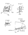
- FIGs. 5-8 the parallel parallelogram faces and trapezoidal geometry of cutter insert 11 per se is illustrated.
- Such geometry is known in the art in general configuration as disclosed in U. S. Patent No. 3,541,655 with the exception of applicant's addition of the primary angle 27 on each cutting face extending from the cutting edge to a depth preferably no greater than stock removal cutting chip thickness at a point of intersection with the positive clearance angle 28 of the main cutting face 17 preferably in the order of 17-20° positive.
- the primary angle 27 shown neutral in full line and dotted line angle designated " ⁇ " at 29 may be any angle from 90° as shown at 30 to an angle, ⁇ 29, which is less than the clearance angle 28, again with a preferred range of 0-5° positive.
- the parallelogram/trapezoid configuration provides four index positions for each insert in either face mill or boring cutter application through the provision of double taper screw hole 31 in the insert to accommodate two indexing positions on either side.
- the provision of a less acute primary angle effectively strengthens the cutting edge without increasing the horsepower required to form the cut and without losing the characteristics of a substantially positive cutting action.
- the improvement is particularly useful on current brittle materials such as ceramics, silicon nitrides or combinations thereof which can be employed with higher cutting speeds and durability if properly protected against edge fracturing incident to the conventional unqualified acute cutting edge angle of a positive cutting face combined with a flank clearance angle.
- the primary angle provides quieter, smoother and better size control cutting action because the edge is more durable.
Landscapes
- Engineering & Computer Science (AREA)
- Mechanical Engineering (AREA)
- Cutting Tools, Boring Holders, And Turrets (AREA)
- Milling Processes (AREA)
- Ceramic Products (AREA)
Applications Claiming Priority (2)
| Application Number | Priority Date | Filing Date | Title |
|---|---|---|---|
| US6136987A | 1987-06-15 | 1987-06-15 | |
| US61369 | 1987-06-15 |
Publications (1)
| Publication Number | Publication Date |
|---|---|
| EP0295487A1 true EP0295487A1 (fr) | 1988-12-21 |
Family
ID=22035350
Family Applications (1)
| Application Number | Title | Priority Date | Filing Date |
|---|---|---|---|
| EP88108630A Withdrawn EP0295487A1 (fr) | 1987-06-15 | 1988-05-30 | Elément tranchant |
Country Status (3)
| Country | Link |
|---|---|
| EP (1) | EP0295487A1 (fr) |
| JP (1) | JPS6416303A (fr) |
| DE (1) | DE295487T1 (fr) |
Cited By (1)
| Publication number | Priority date | Publication date | Assignee | Title |
|---|---|---|---|---|
| EP4306245A1 (fr) * | 2022-07-11 | 2024-01-17 | Tungaloy Corporation | Plaquette de coupe et outil de coupe équipé de la plaquette de coupe |
Families Citing this family (1)
| Publication number | Priority date | Publication date | Assignee | Title |
|---|---|---|---|---|
| JP2009184036A (ja) * | 2008-02-04 | 2009-08-20 | Mitsubishi Materials Corp | 切削工具 |
Citations (5)
| Publication number | Priority date | Publication date | Assignee | Title |
|---|---|---|---|---|
| US3541655A (en) * | 1967-12-29 | 1970-11-24 | Carmet Co | Indexable and reversible cutting inserts |
| FR2172542A5 (fr) * | 1972-02-17 | 1973-09-28 | Ballesteros Daniel | |
| US3930529A (en) * | 1974-05-09 | 1976-01-06 | Kennametal Inc. | Method and apparatus for removing tread from tires |
| FR2312325A1 (fr) * | 1975-05-19 | 1976-12-24 | Kennametal Inc | Element coupant pour fraises a rainurer |
| DE2938381A1 (de) * | 1979-02-02 | 1980-04-17 | Vunar Vyskumny Ustav Naradia | Auswechselbare schneideplatte, vor allem zum fraesen |
-
1988
- 1988-05-30 DE DE198888108630T patent/DE295487T1/de active Pending
- 1988-05-30 EP EP88108630A patent/EP0295487A1/fr not_active Withdrawn
- 1988-06-14 JP JP63144906A patent/JPS6416303A/ja active Pending
Patent Citations (5)
| Publication number | Priority date | Publication date | Assignee | Title |
|---|---|---|---|---|
| US3541655A (en) * | 1967-12-29 | 1970-11-24 | Carmet Co | Indexable and reversible cutting inserts |
| FR2172542A5 (fr) * | 1972-02-17 | 1973-09-28 | Ballesteros Daniel | |
| US3930529A (en) * | 1974-05-09 | 1976-01-06 | Kennametal Inc. | Method and apparatus for removing tread from tires |
| FR2312325A1 (fr) * | 1975-05-19 | 1976-12-24 | Kennametal Inc | Element coupant pour fraises a rainurer |
| DE2938381A1 (de) * | 1979-02-02 | 1980-04-17 | Vunar Vyskumny Ustav Naradia | Auswechselbare schneideplatte, vor allem zum fraesen |
Cited By (1)
| Publication number | Priority date | Publication date | Assignee | Title |
|---|---|---|---|---|
| EP4306245A1 (fr) * | 2022-07-11 | 2024-01-17 | Tungaloy Corporation | Plaquette de coupe et outil de coupe équipé de la plaquette de coupe |
Also Published As
| Publication number | Publication date |
|---|---|
| JPS6416303A (en) | 1989-01-19 |
| DE295487T1 (de) | 1989-07-13 |
Similar Documents
| Publication | Publication Date | Title |
|---|---|---|
| US7094007B2 (en) | Tangential cutting insert and milling cutter | |
| JP3057781B2 (ja) | スローアウェイチップ | |
| EP2119520B1 (fr) | Plaquette de fraisage | |
| US7972091B2 (en) | Milling tool, a cutting insert for milling tool as well as a solid milling tool | |
| US4597695A (en) | Face milling apparatus with eight-edged insert | |
| EP0494646B1 (fr) | Plaquette de coupe à contrÔle de copeaux | |
| US5330295A (en) | Indexable insert for roughing and finishing | |
| EP0464825B1 (fr) | Plaquette de coupe et outil de coupe | |
| US5028175A (en) | Indexable insert for roughing and finishing | |
| US20050042044A1 (en) | Tangential cutting insert and milling cutter | |
| US5158401A (en) | Indexable insert for roughing and finishing | |
| EP0462954B1 (fr) | Fraise à bout sphérique et plaquette de coupe pour une telle fraise | |
| JP2522862Y2 (ja) | 転削工具 | |
| JP2002066811A (ja) | スローアウェイチップ | |
| US5020944A (en) | Indexable insert for roughing and finishing | |
| EP0514894A2 (fr) | Fraise sphérique | |
| EP0295487A1 (fr) | Elément tranchant | |
| JP3118956B2 (ja) | スローアウェイチップ | |
| CA1260689A (fr) | Mise de fraise en bout | |
| JPH0698524B2 (ja) | スロ−アウエイチツプ | |
| JPH0433565B2 (fr) | ||
| JPS6119859Y2 (fr) | ||
| US20250289068A1 (en) | Double-sided negative cutting insert and milling tool | |
| JP3010760B2 (ja) | スローアウェイチップ及びスローアウェイ式カッタ | |
| JPH05138425A (ja) | ボールエンドミル |
Legal Events
| Date | Code | Title | Description |
|---|---|---|---|
| PUAI | Public reference made under article 153(3) epc to a published international application that has entered the european phase |
Free format text: ORIGINAL CODE: 0009012 |
|
| AK | Designated contracting states |
Kind code of ref document: A1 Designated state(s): DE SE |
|
| DET | De: translation of patent claims | ||
| 17P | Request for examination filed |
Effective date: 19890621 |
|
| 17Q | First examination report despatched |
Effective date: 19900809 |
|
| STAA | Information on the status of an ep patent application or granted ep patent |
Free format text: STATUS: THE APPLICATION IS DEEMED TO BE WITHDRAWN |
|
| 18D | Application deemed to be withdrawn |
Effective date: 19901219 |