EP0295641A2 - Système de haut-parleur - Google Patents
Système de haut-parleur Download PDFInfo
- Publication number
- EP0295641A2 EP0295641A2 EP88109508A EP88109508A EP0295641A2 EP 0295641 A2 EP0295641 A2 EP 0295641A2 EP 88109508 A EP88109508 A EP 88109508A EP 88109508 A EP88109508 A EP 88109508A EP 0295641 A2 EP0295641 A2 EP 0295641A2
- Authority
- EP
- European Patent Office
- Prior art keywords
- horn
- loudspeaker
- unit
- frequency
- loudspeaker system
- Prior art date
- Legal status (The legal status is an assumption and is not a legal conclusion. Google has not performed a legal analysis and makes no representation as to the accuracy of the status listed.)
- Granted
Links
Images


Classifications
-
- H—ELECTRICITY
- H04—ELECTRIC COMMUNICATION TECHNIQUE
- H04R—LOUDSPEAKERS, MICROPHONES, GRAMOPHONE PICK-UPS OR LIKE ACOUSTIC ELECTROMECHANICAL TRANSDUCERS; ELECTRIC HEARING AIDS; PUBLIC ADDRESS SYSTEMS
- H04R1/00—Details of transducers, loudspeakers or microphones
- H04R1/20—Arrangements for obtaining desired frequency or directional characteristics
- H04R1/22—Arrangements for obtaining desired frequency or directional characteristics for obtaining desired frequency characteristic only
- H04R1/28—Transducer mountings or enclosures modified by provision of mechanical or acoustic impedances, e.g. resonator, damping means
- H04R1/2807—Enclosures comprising vibrating or resonating arrangements
- H04R1/2853—Enclosures comprising vibrating or resonating arrangements using an acoustic labyrinth or a transmission line
- H04R1/2857—Enclosures comprising vibrating or resonating arrangements using an acoustic labyrinth or a transmission line for loudspeaker transducers
-
- H—ELECTRICITY
- H04—ELECTRIC COMMUNICATION TECHNIQUE
- H04R—LOUDSPEAKERS, MICROPHONES, GRAMOPHONE PICK-UPS OR LIKE ACOUSTIC ELECTROMECHANICAL TRANSDUCERS; ELECTRIC HEARING AIDS; PUBLIC ADDRESS SYSTEMS
- H04R1/00—Details of transducers, loudspeakers or microphones
- H04R1/20—Arrangements for obtaining desired frequency or directional characteristics
- H04R1/22—Arrangements for obtaining desired frequency or directional characteristics for obtaining desired frequency characteristic only
- H04R1/28—Transducer mountings or enclosures modified by provision of mechanical or acoustic impedances, e.g. resonator, damping means
- H04R1/2807—Enclosures comprising vibrating or resonating arrangements
- H04R1/2861—Enclosures comprising vibrating or resonating arrangements using a back-loaded horn
- H04R1/2865—Enclosures comprising vibrating or resonating arrangements using a back-loaded horn for loudspeaker transducers
-
- H—ELECTRICITY
- H04—ELECTRIC COMMUNICATION TECHNIQUE
- H04R—LOUDSPEAKERS, MICROPHONES, GRAMOPHONE PICK-UPS OR LIKE ACOUSTIC ELECTROMECHANICAL TRANSDUCERS; ELECTRIC HEARING AIDS; PUBLIC ADDRESS SYSTEMS
- H04R1/00—Details of transducers, loudspeakers or microphones
- H04R1/20—Arrangements for obtaining desired frequency or directional characteristics
- H04R1/22—Arrangements for obtaining desired frequency or directional characteristics for obtaining desired frequency characteristic only
- H04R1/28—Transducer mountings or enclosures modified by provision of mechanical or acoustic impedances, e.g. resonator, damping means
- H04R1/2807—Enclosures comprising vibrating or resonating arrangements
- H04R1/283—Enclosures comprising vibrating or resonating arrangements using a passive diaphragm
- H04R1/2834—Enclosures comprising vibrating or resonating arrangements using a passive diaphragm for loudspeaker transducers
Definitions
- the present invention relates to a loudspeaker system of a type having a horn behind a loudspeaker unit.
- loudspeaker systems capable of enhancing sounds within a low frequency region
- a loudspeaker system of back-loaded horn type As one example of loudspeaker systems capable of enhancing sounds within a low frequency region, there is well known a loudspeaker system of back-loaded horn type.
- This prior art loudspeaker system of back-loaded horn type comprises a loudspeaker unit having a horn disposed behind the loudspeaker unit and has a cavity defined in the connection between the loudspeaker unit and the throat of the horn.
- the mechanical reactance presented by the cavity that is, the acoustic volume
- the mechanical reactance presented by the cavity that is, the acoustic volume
- the mechanical reactance of the acoustic volume lowers to a value smaller than the mechanical impedance of the throat of the horn. Accordingly, the acoustic sounds emanating from the horn attenuate and a relatively large portion of the acoustic output emanates from the front of the loudspeaker unit.
- the acoustic radiation efficiency at the low frequency region can be improved by the presence of the horn.
- the opening (mouth) of the horn must be increased.
- the cavity defined at the connection between the back of the loudspeaker unit and the horn throat which cavity acts to attenuate medium-to-high frequency sounds which would propagate from the mouth of the horn, must have a relatively great volume in order for the medium-to-high frequency sounds to be completely attenuated and, in practice, with increase in frequency, the horn tends to undergo the above described operation repeatedly to such an extent as to result in creation of hills and dale in sound pressure of composite sounds formed by the sound propagating from the front of the loudspeaker unit and those from the mouth of the horn. This brings about reduction in quality of the sounds reproduced from the loudspeaker system as a whole.
- the present invention has been developed with a view to substantially solving the above described problems and has for its essential object to provide an improved loudspeaker system having an improved acoustical radiation efficiency at the low frequency range and capable of providing a high quality sound having a minimized distortion in sound pressure over a relatively wide range.
- a loudspeaker system comprises a loudspeaker unit, a horn unit having a throat coupled to the back of the loudspeaker and an acoustic filter provided in the horn.
- the acoustic filter may be constituted by a throat or constricted area defined in the horn unit and having a cross-sectional area smaller than that of the horn unit, or by a shielding plate in the form of a draw cone made of a vibratory diaphragm that is supported by a suspension means within a substantially intermediate portion of the horn unit.
- the horn unit disposed behind the loudspeaker unit comprises a horn complex constituted by a plurality of horns having respective portions which are different in length from each other and which have a common mouth, the length of each of said portions being smaller than one half of the overall length of the horn unit.
- the acoustic filter is disposed within a common horn portion.
- the provision of the acoustic filter which may be either the throat or constricted area having its cross-sectional area smaller than that of the horn or the drone cone inside the horn is effective in that a portion of the horn between the loudspeaker unit and the acoustic filter acts at the frequency fd as if it were a straight acoustic tube to produce a primary harmonic resonance.
- the sound pressure immediately preceding the acoustic filter is very high enough to permit a sound pressure proportional to this sound pressure to be reproduced from the mouth of the horn.
- the sound pressure propagating from the horn to the free atmosphere is high and the composite sound pressure of the loudspeaker system as a whole which is the difference between these sounds is of a level sufficient to compensate for the dale in the sound pressure produced by the prior art loudspeaker system.
- the acoustic filter provided according to the present invention has a reactance component, the acoustic filter concurrently acts as a acoustic high frequency cut-off filter effective to cut off the medium-to-high frequency range radiated from the mouth of the horn, and therefore, at this frequency range, the interference between the sound propagating from the front of the loudspeaker unit and the sound propagating from the mouth of the horn can be eliminated to accomplish the reproduction of a flat medium-to-high frequency range.
- the horn length of another one of the horns is limited to an even-number multiple of the one-half wavelength and that the horns are coupled to the common mouth to complete the horn complex while the acoustic filter is disposed in the common horn portion, hills and dales produced in the respective sound pressures propagating in these horns can be counteracted to diminish and, in combination with the cumulative effects of the acoustic filter, the sound pressure characteristic can be rendered very flat as compared with that in the prior art loudspeaker system. Therefore, with the present invention, it is possible to provide the loudspeaker system having no substantial reduction in quality of the reproduced sounds.
- a loudspeaker system shown therein comprises a cabinet 2 of generally box-like configuration, a loudspeaker unit 1 fixedly installed within the cabinet 2, and a horn 4 having a throat 3, communicated with an opening defined in a rear wall of the cabinet 2, and also having a mouth 6 opposite to the throat 3.
- the horn 4 has an acoustic filter 5 formed therein and constituted by a throat or constricted area having a cross-sectional area smaller than that of the horn 4 and positioned intermediate between the throat 3 and the mouth 6.
- the loudspeaker system so constructed as shown in Fig. 1 operates in the following manner.
- a sound pressure radiated from the loudspeaker system as a whole is a composite of the sound propagating from the front of the loudspeaker unit 1 and the sound propagating from the mouth 6 of the horn 4.
- the length Lf of an upstream portion of the horn 4 from the throat 3 to the acoustic filter 5 is so selected as to be generally equal to one half of the wavelength of the first frequency fd of the low frequency range in the cyclic dales of sound pressure which would occur as a result of the opposite phase relationship between the sound from the front of the loudspeaker unit 1 and that from the mouth 6 of the horn 6.
- the acoustic filter 5 so disposed as hereinabove described is effective to render the acoustical impedance of the horn 4 to be discontinuous and acts as if it were an acoustic tube having its opposite ends closed by the loudspeaker unit 1 and the acoustic filter 5.
- a node occurs at an intermediate point while loops occur at opposite ends, and a relatively great sound pressure occur at the entrance to the acoustic filter 5.
- the horn operates in a manner similar to the horn in the conventional loudspeaker system with a new source of sound constituted at the entrance to the acoustic filter 5, thereby producing from the mouth 6 of the horn a sound pressure proportional to the great sound pressure of standing waves.
- the downstream portion of the horn 4 acts in a manner similar to the horn used in the prior art loudspeaker system as if a source of sound were to be positioned at the entrance to the acoustic filter 5, thereby to produce from the mouth 6 of the horn 4 acoustical sounds of a magnitude proportional to the magnitude of the standing waves within the upstream portion of the horn 4.
- the position of the acoustic filter 5 is so selected as to be about equal to one half of the wavelength as the frequency fd, the primary harmonic resonance of the close-ended straight acoustic tube occurs between the loudspeaker unit 1 and the acoustic filter 5. Because of this, at a frequency range in the vicinity of the frequency fd, the sound pressure radiated from the mouth 6 of the horn will become very great, and the difference between the sound propagating from the front of the loudspeaker unit 1 and that from the horn is of a level sufficient to compensate for the relatively large dale produced in the sound pressure according to the prior art system.
- the sound pressure versus frequency characteristic of the loudspeaker system according to the embodiment shown in Fig.
- the reactance component increases with increase of the frequency enough to cut off a component of the intermediate-to-high frequency range then passing through the acoustic filter 5, thereby considerably attenuating the level of the sound pressure radiated from the mouth 6 of the horn while acting as an acoustic high frequency cut-off filter.
- the sound pressure within the medium-to-high frequency range produced by the loudspeaker system is transformed into sounds substantially radiated from the front of the loudspeaker unit 1, and the hills and dales in the sound pressure which are formed by the interference between the sounds radiating from the front of the loudspeaker unit 1 and the mouth 6 of the horn can be minimized.
- the loudspeaker system according to a second preferred embodiment of the present invention is illustrated in Fig. 3.
- the loudspeaker system shown in Fig. 3 may possibly be a version of the loudspeaker system of Fig. 1 in which a portion of the throat of the horn 4 is divided into a plurality of sections of different lengths.
- the horn unit shown in Fig. 3 may be termed a composite horn and is comprised of two horn sections 9 and 10 of different lengths having their respective throats 7 and 9 communicated to the cabinet 2 behind the loudspeaker unit 1, respective openings of said horn sections 9 and 10 opposite to the throats 7 and 9 being communicated with a common horn section 11.
- the common horn section 11 has a constricted area or throat defined therein so as to constitute an acoustic filter 15 similar to the acoustic filter 5 shown in Fig. 1.
- the loudspeaker system according to the second embodiment of the present invention shown in and described with reference to Fig. 3 operates in the following manner. Assuming that the respective lengths of the horn sections 9 and 10 are expressed by L1 and L2 and the length of the common horn section 11 is expressed by L3, the operation of the horn unit at the medium-to-high frequency range at which the wavelength is relatively short can be considered as that of a composite of horns one having a length of L1 + L3 and the other having a length of L2 + L3.
- Fig. 4 illustrates sound pressure versus frequency characteristics of the respective horns of L1 + L3 and L2 + L3 in length, respectively, with no acoustic filter used in the horn unit.
- the sounds radiated from the front of the loudspeaker unit and that from the mouth of the horn unit are matched in phase with each other while, at the frequency at which the horn length is generally equal to an even-number multiple of the one-half wavelength, the both are opposite in phase to each other.
- the respective horn lengths of the horn sections are so selected that, at the frequency at which the horn length of one horn section is equal to an odd number multiple of the one-half wavelength, the horn length of the other horn section becomes equal to an even-number multiple of the one-half wavelength, and vice versa.
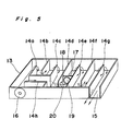
- Fig. 5 illustrates a loudspeaker system according to a third preferred embodiment of the present invention in a perspective representation with a portion cut away.
- the loudspeaker system shown therein comprises a cabinet 13 of generally rectangular box-like configuration having a plurality of partition plates 14a to 14h so disposed and so positioned within the interior of the cabinet 13 as to form two acoustic tubes of different lengths adjacent a loudspeaker unit 16 and one common acoustic tube communicated at one end with the shorter and longer acoustic tubes and at the opposite end 15 opening to the free atmosphere.
- acoustic filter 17 that is in the form of a drone cone constituted by a shielding plate 18, a vibratory diaphragm 19 and a suspension 20.
- Arrow-headed broken lines employed in Fig. 5 represent the passage of sounds through the shorter acoustic tube whereas arrow-headed solid lines employed therein represent the passage of sounds through the longer acoustic tube.
- the acoustic filter 17 is constituted by the drone cone 19 supported through the suspension 20 by the shielding plate 18 capable of acoustically shielding the interior of the horn as shown in Fig. 5, the acoustical impedance within the interior of the horn can be rendered discontinuous, and in the vicinity of the frequency at which the length between the horn throat and the drone cone is equal to the one-half of the wavelength, it can work in a manner similar to the close-ended straight acoustic tube thereby to exhibiting effects similar to those exhibited by the loudspeaker system shown in and described with reference to Fig. 1.
- the position of the acoustic filter is so selected as to be spaced from the loudspeaker unit a distance corresponding to about one half of the wavelength at the frequency fd.
- the position of the acoustic filter may require adjustment depending on the volume of the space behind the loudspeaker unit and/or the ratio between the size of a vibrating diaphragm of the loudspeaker unit and the size of the horn throat.
Landscapes
- Health & Medical Sciences (AREA)
- Otolaryngology (AREA)
- Physics & Mathematics (AREA)
- Engineering & Computer Science (AREA)
- Acoustics & Sound (AREA)
- Signal Processing (AREA)
- Obtaining Desirable Characteristics In Audible-Bandwidth Transducers (AREA)
Applications Claiming Priority (8)
| Application Number | Priority Date | Filing Date | Title |
|---|---|---|---|
| JP62149647A JP2653377B2 (ja) | 1987-06-16 | 1987-06-16 | スピーカシステム |
| JP149647/87 | 1987-06-16 | ||
| JP177427/87 | 1987-07-16 | ||
| JP17742787A JPH0632527B2 (ja) | 1987-07-16 | 1987-07-16 | スピ−カシステム |
| JP248718/87 | 1987-10-01 | ||
| JP24871887A JPH0691680B2 (ja) | 1987-10-01 | 1987-10-01 | スピーカシステム |
| JP68563/88 | 1988-03-22 | ||
| JP63068563A JP2517053B2 (ja) | 1988-03-22 | 1988-03-22 | スピ―カシステム |
Publications (3)
| Publication Number | Publication Date |
|---|---|
| EP0295641A2 true EP0295641A2 (fr) | 1988-12-21 |
| EP0295641A3 EP0295641A3 (en) | 1990-12-27 |
| EP0295641B1 EP0295641B1 (fr) | 1993-09-01 |
Family
ID=27465012
Family Applications (1)
| Application Number | Title | Priority Date | Filing Date |
|---|---|---|---|
| EP88109508A Expired - Lifetime EP0295641B1 (fr) | 1987-06-16 | 1988-06-15 | Système de haut-parleur |
Country Status (3)
| Country | Link |
|---|---|
| US (1) | US4930596A (fr) |
| EP (1) | EP0295641B1 (fr) |
| DE (1) | DE3883624T2 (fr) |
Cited By (5)
| Publication number | Priority date | Publication date | Assignee | Title |
|---|---|---|---|---|
| EP0429121A1 (fr) * | 1989-11-16 | 1991-05-29 | Koninklijke Philips Electronics N.V. | Système de haut-parleurs comportant un résonateur de Helmholtz couplé à un tube acoustique |
| WO1998051121A1 (fr) * | 1997-05-02 | 1998-11-12 | B & W Loudspeakers Limited | Systemes haut-parleur |
| DE102012107645A1 (de) * | 2012-08-21 | 2014-02-27 | D & B Audiotechnik Gmbh | Akustischer wandler |
| ITMO20130336A1 (it) * | 2013-12-11 | 2015-06-12 | Ixoost S R L | Dispositivo per la diffusione del suono |
| EP3107311A1 (fr) * | 2015-06-18 | 2016-12-21 | Yamaha Corporation | Structure acoustique et panneau acoustique |
Families Citing this family (42)
| Publication number | Priority date | Publication date | Assignee | Title |
|---|---|---|---|---|
| US5111509A (en) * | 1987-12-25 | 1992-05-05 | Yamaha Corporation | Electric acoustic converter |
| US5025886A (en) * | 1990-06-01 | 1991-06-25 | Jung Gin K | Multi-ported and multi-directional loudspeaker system |
| US5206465A (en) * | 1990-06-01 | 1993-04-27 | Gin Kon Jung | Sound collecting and concentrating device for attaching to the back of a loudspeaker |
| US5296656A (en) * | 1990-06-01 | 1994-03-22 | Gin Kon Jung | Sound collecting and concentrating device for attaching to the back of multiple loudspeakers |
| US5187333A (en) * | 1990-12-03 | 1993-02-16 | Adair John F | Coiled exponential bass/midrange/high frequency horn loudspeaker |
| US5740259A (en) * | 1992-06-04 | 1998-04-14 | Bose Corporation | Pressure wave transducing |
| US6278789B1 (en) * | 1993-05-06 | 2001-08-21 | Bose Corporation | Frequency selective acoustic waveguide damping |
| KR960011026B1 (ko) * | 1993-07-26 | 1996-08-16 | 대우전자 주식회사 | 텔레비전의 스피커시스템 |
| US6141428A (en) * | 1993-10-28 | 2000-10-31 | Narus; Chris | Audio speaker system |
| US5535284A (en) * | 1994-08-03 | 1996-07-09 | Thornhill; James A. | Woofer speaker and acoustically coupled sub-woofer speaker system |
| US5734728A (en) * | 1994-11-30 | 1998-03-31 | Meissner; Juergen P. | Portable sound speaker system and driving circuit therefor |
| US5920633A (en) * | 1996-02-12 | 1999-07-06 | Yang; Yi-Fu | Thin-wall multi-concentric cylinder speaker enclosure with audio amplifier tunable to listening room |
| US5844176A (en) * | 1996-09-19 | 1998-12-01 | Clark; Steven | Speaker enclosure having parallel porting channels for mid-range and bass speakers |
| JPH10313495A (ja) * | 1997-05-12 | 1998-11-24 | Sony Corp | 音響装置 |
| US5872339A (en) * | 1997-08-28 | 1999-02-16 | Hanson; Charles Anthony | High performance loudspeaker system |
| US6771787B1 (en) * | 1998-09-03 | 2004-08-03 | Bose Corporation | Waveguide electroacoustical transducing |
| US6912290B1 (en) * | 2000-11-16 | 2005-06-28 | Alpine Electronics, Inc. | Speaker unit for low frequency reproduction |
| RU2201044C2 (ru) * | 2001-01-12 | 2003-03-20 | Гоц Сергей Степанович | Акустическая система |
| FR2824990B1 (fr) * | 2001-05-15 | 2003-09-26 | Jean Pierre Morkerken | Emetteur de son et haut-parleur |
| US7392880B2 (en) * | 2002-04-02 | 2008-07-01 | Gibson Guitar Corp. | Dual range horn with acoustic crossover |
| TW568493U (en) * | 2003-01-21 | 2003-12-21 | High Tech Comp Corp | Trumpet module |
| US7565948B2 (en) * | 2004-03-19 | 2009-07-28 | Bose Corporation | Acoustic waveguiding |
| US7584820B2 (en) * | 2004-03-19 | 2009-09-08 | Bose Corporation | Acoustic radiating |
| US20060078136A1 (en) * | 2004-10-07 | 2006-04-13 | Stiles Enrique M | Chamber-loaded augmented passive radiator |
| US7748495B2 (en) * | 2005-04-20 | 2010-07-06 | Krueger Paul M | Tubular loudspeaker |
| JP2011501579A (ja) | 2007-10-22 | 2011-01-06 | デイビッド マエシバ, | 音響システム |
| US20090188745A1 (en) * | 2008-01-30 | 2009-07-30 | Paul Wilke | Helmholz resonator loudspeaker |
| US8295526B2 (en) * | 2008-02-21 | 2012-10-23 | Bose Corporation | Low frequency enclosure for video display devices |
| US8351629B2 (en) * | 2008-02-21 | 2013-01-08 | Robert Preston Parker | Waveguide electroacoustical transducing |
| US8351630B2 (en) * | 2008-05-02 | 2013-01-08 | Bose Corporation | Passive directional acoustical radiating |
| WO2011007436A1 (fr) * | 2009-07-16 | 2011-01-20 | 株式会社 東芝 | Dispositif de reproduction acoustique |
| US8094855B2 (en) * | 2009-09-08 | 2012-01-10 | Clements Philip R | Inverse horn loudspeakers |
| US8265310B2 (en) * | 2010-03-03 | 2012-09-11 | Bose Corporation | Multi-element directional acoustic arrays |
| US8553894B2 (en) | 2010-08-12 | 2013-10-08 | Bose Corporation | Active and passive directional acoustic radiating |
| JP5817762B2 (ja) * | 2013-03-07 | 2015-11-18 | ヤマハ株式会社 | 音響装置 |
| JP6258089B2 (ja) * | 2014-03-18 | 2018-01-10 | 株式会社東芝 | スピーカシステム |
| US10057701B2 (en) | 2015-03-31 | 2018-08-21 | Bose Corporation | Method of manufacturing a loudspeaker |
| US9451355B1 (en) | 2015-03-31 | 2016-09-20 | Bose Corporation | Directional acoustic device |
| KR101901906B1 (ko) * | 2017-05-25 | 2018-09-27 | 주식회사 성주음향 | 혼 스피커 |
| US9820032B1 (en) * | 2017-06-16 | 2017-11-14 | Unisinger LTD. | Speaker system for high fidelity reproduction of audio signals |
| GB2577569B (en) * | 2018-09-29 | 2022-06-15 | Barefaced Ltd | Loudspeaker enclosure with slot/horn apparatus for improved polar response and low frequency output |
| CN116491128A (zh) * | 2020-11-13 | 2023-07-25 | 松下电器(美国)知识产权公司 | 音响装置 |
Family Cites Families (9)
| Publication number | Priority date | Publication date | Assignee | Title |
|---|---|---|---|---|
| US1965405A (en) * | 1933-02-28 | 1934-07-03 | Bell Telephone Labor Inc | Acoustic device |
| US2866513A (en) * | 1952-11-24 | 1958-12-30 | Edward V Bracken | Apparatus for generating sound |
| US3122215A (en) * | 1962-02-05 | 1964-02-25 | Eugene E Sutton | Resonant, acoustical booster with air damping |
| US3669215A (en) * | 1970-02-12 | 1972-06-13 | Sansui Electric Co | Passive radiator for use in a bass reflex loudspeaker system |
| JPS5037425A (fr) * | 1973-08-04 | 1975-04-08 | ||
| US3923124A (en) * | 1974-01-02 | 1975-12-02 | John P Hancock | Back loaded folded corner horn speaker |
| FR2470511A1 (fr) * | 1979-11-20 | 1981-05-29 | Faugeras Alain | Enceinte acoustique du type " actif - passif " associee a un resonateur |
| US4301332A (en) * | 1980-01-08 | 1981-11-17 | Norman Dusanek | Woofer loudspeaker |
| US4524846A (en) * | 1983-03-02 | 1985-06-25 | Whitby Ronney J | Loudspeaker system |
-
1988
- 1988-06-09 US US07/204,523 patent/US4930596A/en not_active Expired - Lifetime
- 1988-06-15 DE DE88109508T patent/DE3883624T2/de not_active Expired - Lifetime
- 1988-06-15 EP EP88109508A patent/EP0295641B1/fr not_active Expired - Lifetime
Cited By (12)
| Publication number | Priority date | Publication date | Assignee | Title |
|---|---|---|---|---|
| EP0429121A1 (fr) * | 1989-11-16 | 1991-05-29 | Koninklijke Philips Electronics N.V. | Système de haut-parleurs comportant un résonateur de Helmholtz couplé à un tube acoustique |
| US5261006A (en) * | 1989-11-16 | 1993-11-09 | U.S. Philips Corporation | Loudspeaker system comprising a helmholtz resonator coupled to an acoustic tube |
| WO1998051121A1 (fr) * | 1997-05-02 | 1998-11-12 | B & W Loudspeakers Limited | Systemes haut-parleur |
| US6377696B1 (en) | 1997-05-02 | 2002-04-23 | B & W Loudspeakers Limited | Loudspeaker systems |
| DE102012107645A1 (de) * | 2012-08-21 | 2014-02-27 | D & B Audiotechnik Gmbh | Akustischer wandler |
| DE102012107645B4 (de) * | 2012-08-21 | 2015-04-30 | D & B Audiotechnik Gmbh | Akustischer wandler |
| ITMO20130336A1 (it) * | 2013-12-11 | 2015-06-12 | Ixoost S R L | Dispositivo per la diffusione del suono |
| WO2015087246A1 (fr) * | 2013-12-11 | 2015-06-18 | Ixoost S.R.L. | Dispositif pour la diffusion d'un son |
| EP3107311A1 (fr) * | 2015-06-18 | 2016-12-21 | Yamaha Corporation | Structure acoustique et panneau acoustique |
| CN106257933A (zh) * | 2015-06-18 | 2016-12-28 | 雅马哈株式会社 | 声学结构和音响板 |
| US10045119B2 (en) | 2015-06-18 | 2018-08-07 | Yamaha Corporation | Acoustic structure and acoustic panel |
| CN106257933B (zh) * | 2015-06-18 | 2019-08-30 | 雅马哈株式会社 | 声学结构和音响板 |
Also Published As
| Publication number | Publication date |
|---|---|
| DE3883624D1 (de) | 1993-10-07 |
| DE3883624T2 (de) | 1993-12-16 |
| EP0295641B1 (fr) | 1993-09-01 |
| US4930596A (en) | 1990-06-05 |
| EP0295641A3 (en) | 1990-12-27 |
Similar Documents
| Publication | Publication Date | Title |
|---|---|---|
| EP0295641B1 (fr) | Système de haut-parleur | |
| KR0158885B1 (ko) | 음향관에 결합된 헬름홀쯔 공명기를 구비한 확성기 시스템 | |
| CA1226820A (fr) | Generateur d'ondes de pression | |
| US5092424A (en) | Electroacoustical transducing with at least three cascaded subchambers | |
| US4391346A (en) | Loud-speaker | |
| US7207413B2 (en) | Closed loop embedded audio transmission line technology for loudspeaker enclosures and systems | |
| US6002781A (en) | Speaker system | |
| US3944757A (en) | High-fidelity moving-coil loudspeaker | |
| US6343134B1 (en) | Loudspeaker and horn with an additional transducer | |
| JPH06205491A (ja) | スピーカーシステム | |
| GB2258365A (en) | Speaker system with opposed drive units | |
| WO2000065874A1 (fr) | Reproduction du son utilisant des baffles a ouverture a groupement d'unites | |
| US5804774A (en) | Ported reflex horn | |
| CN1187087A (zh) | 视频显示装置用的扬声器壳体 | |
| US5844176A (en) | Speaker enclosure having parallel porting channels for mid-range and bass speakers | |
| GB2256343A (en) | High efficiency low frequency speaker system | |
| US20020106097A1 (en) | Sound reproduction employing unity summation aperture loudspeakers | |
| US6038326A (en) | Loudspeaker and horn with an additional transducer | |
| US2816619A (en) | Acoustic transducers | |
| US4196790A (en) | Acoustic transducer having multiple frequency resonance | |
| US3186509A (en) | High fidelity loudspeaker system | |
| JPH099384A (ja) | 定在波等の低減装置 | |
| CN119485119A (zh) | 在宽频范围内减少后侧声音辐射的扬声器系统 | |
| JP2517053B2 (ja) | スピ―カシステム | |
| CN109040897B (zh) | 高清晰度扬声器音箱 |
Legal Events
| Date | Code | Title | Description |
|---|---|---|---|
| PUAI | Public reference made under article 153(3) epc to a published international application that has entered the european phase |
Free format text: ORIGINAL CODE: 0009012 |
|
| 17P | Request for examination filed |
Effective date: 19880615 |
|
| AK | Designated contracting states |
Kind code of ref document: A2 Designated state(s): DE FR GB |
|
| PUAL | Search report despatched |
Free format text: ORIGINAL CODE: 0009013 |
|
| AK | Designated contracting states |
Kind code of ref document: A3 Designated state(s): DE FR GB |
|
| 17Q | First examination report despatched |
Effective date: 19921201 |
|
| GRAA | (expected) grant |
Free format text: ORIGINAL CODE: 0009210 |
|
| AK | Designated contracting states |
Kind code of ref document: B1 Designated state(s): DE FR GB |
|
| REF | Corresponds to: |
Ref document number: 3883624 Country of ref document: DE Date of ref document: 19931007 |
|
| ET | Fr: translation filed | ||
| PLBE | No opposition filed within time limit |
Free format text: ORIGINAL CODE: 0009261 |
|
| STAA | Information on the status of an ep patent application or granted ep patent |
Free format text: STATUS: NO OPPOSITION FILED WITHIN TIME LIMIT |
|
| 26N | No opposition filed | ||
| REG | Reference to a national code |
Ref country code: GB Ref legal event code: IF02 |
|
| REG | Reference to a national code |
Ref country code: GB Ref legal event code: 746 Effective date: 20031002 |
|
| REG | Reference to a national code |
Ref country code: FR Ref legal event code: D6 |
|
| PGFP | Annual fee paid to national office [announced via postgrant information from national office to epo] |
Ref country code: DE Payment date: 20070607 Year of fee payment: 20 |
|
| PGFP | Annual fee paid to national office [announced via postgrant information from national office to epo] |
Ref country code: GB Payment date: 20070613 Year of fee payment: 20 |
|
| PGFP | Annual fee paid to national office [announced via postgrant information from national office to epo] |
Ref country code: FR Payment date: 20070608 Year of fee payment: 20 |
|
| REG | Reference to a national code |
Ref country code: GB Ref legal event code: PE20 Expiry date: 20080614 |
|
| PG25 | Lapsed in a contracting state [announced via postgrant information from national office to epo] |
Ref country code: GB Free format text: LAPSE BECAUSE OF EXPIRATION OF PROTECTION Effective date: 20080614 |