EP0295687A1 - Lese- ond/oder Schreibeinrichtung für eine Zusatzspur eines Kinofilms, insbesondere für eine Tonspur und Beleuchtungsvorrichtung für diese Einrichtung - Google Patents
Lese- ond/oder Schreibeinrichtung für eine Zusatzspur eines Kinofilms, insbesondere für eine Tonspur und Beleuchtungsvorrichtung für diese Einrichtung Download PDFInfo
- Publication number
- EP0295687A1 EP0295687A1 EP88109665A EP88109665A EP0295687A1 EP 0295687 A1 EP0295687 A1 EP 0295687A1 EP 88109665 A EP88109665 A EP 88109665A EP 88109665 A EP88109665 A EP 88109665A EP 0295687 A1 EP0295687 A1 EP 0295687A1
- Authority
- EP
- European Patent Office
- Prior art keywords
- reading
- mirror
- film
- light
- head
- Prior art date
- Legal status (The legal status is an assumption and is not a legal conclusion. Google has not performed a legal analysis and makes no representation as to the accuracy of the status listed.)
- Granted
Links
- 230000003287 optical effect Effects 0.000 claims description 9
- 238000010438 heat treatment Methods 0.000 claims description 3
- 230000003071 parasitic effect Effects 0.000 claims description 2
- 239000004065 semiconductor Substances 0.000 claims description 2
- 230000005236 sound signal Effects 0.000 abstract description 2
- 238000005286 illumination Methods 0.000 description 2
- 238000004519 manufacturing process Methods 0.000 description 2
- 238000001454 recorded image Methods 0.000 description 2
- 230000004075 alteration Effects 0.000 description 1
- 230000001427 coherent effect Effects 0.000 description 1
- 238000005265 energy consumption Methods 0.000 description 1
- 230000001105 regulatory effect Effects 0.000 description 1
- 230000035945 sensitivity Effects 0.000 description 1
Images

Classifications
-
- G—PHYSICS
- G03—PHOTOGRAPHY; CINEMATOGRAPHY; ANALOGOUS TECHNIQUES USING WAVES OTHER THAN OPTICAL WAVES; ELECTROGRAPHY; HOLOGRAPHY
- G03B—APPARATUS OR ARRANGEMENTS FOR TAKING PHOTOGRAPHS OR FOR PROJECTING OR VIEWING THEM; APPARATUS OR ARRANGEMENTS EMPLOYING ANALOGOUS TECHNIQUES USING WAVES OTHER THAN OPTICAL WAVES; ACCESSORIES THEREFOR
- G03B31/00—Associated working of cameras or projectors with sound-recording or sound-reproducing means
- G03B31/02—Associated working of cameras or projectors with sound-recording or sound-reproducing means in which sound track is on a moving-picture film
Definitions
- the present invention relates to cinematographic projection.
- a film used for such a projection has a main strip which occupies a majority fraction of its width and on which the images to be projected follow one another. Appropriate means make it scroll, image by image, by placing the main strip between an intense light source and a lens. From the recorded image thus illuminated, this objective forms an image projected on a screen.
- the film comprises at least one auxiliary recording tape, which is in practice a soundtrack carrying an audible signal, but which could just as easily carry an auxiliary signal of another nature. , for example a clock or synchronization signal etc ...
- a soundtrack comprises a middle fraction of its width which is transparent and two opaque fractions which remain symmetrically on the two edges.
- the signal consists of the variable width of the transparent middle fraction.
- Such a strip is scrolled at constant speed between a lighting head and a photoelectric cell which supplies an electrical signal representative of the sound signal to be reproduced.
- a signal can be amplified and applied to the speakers of a movie theater.
- the lighting head illuminates the film by forming a reading window the length of which constitutes the width of the auxiliary strip and the width of which is oriented according to the direction of travel of the film.
- the writing that is to say the recording of the auxiliary signal, is done analogously using a lighting head forming a reading window of which only a fraction of the length is lit, this fraction being modulated by this signal.
- the bandwidth of such a device is all the smaller the larger the width of the reading window. This is due to the fact that the speed of movement of the film is imposed elsewhere and that the sensitive surface of the photoelectric cell has a width greater than that of the reading window previously defined, only this latter width therefore defining the bandwidth. We therefore seek to reduce the width of this window.
- a lighting head comprising a relatively powerful light source which illuminates a diaphragm pierced with a slot. An image of the thus lit slot is formed on the film by a lens. In this known device, it constitutes the previously defined reading window.
- This known device has in particular two drawbacks. First of all the optical quality of the objective prevents obtaining a window as narrow as one would like it even if the slit pierced in the diaphragm is by itself sufficiently narrow. This limits the bandwidth of the device. Then, given the limited sensitivity of the photocell, the light source must be excessively powerful because only a small fraction of its light passes through the narrow slit pierced in the diaphragm. This results in energy consumption and heating which can be troublesome.
- the object of the present invention is in particular: to increase the bandwidth of a device for reading and / or writing an auxiliary band of a cinematographic film, in particular of a sound band, and / or - to reduce the electrical power consumed and / or the calorific power released by such a device, and / or - to allow easy adjustment of such a device, and / or - make this adjustment independent of the wavelength of the light used, and / or - To easily produce such a device within a preexisting cinematographic device by mounting in this device a space-saving lighting head and / or of simple manufacture.
- this device for reading and / or writing an auxiliary strip of a cinematographic film, in particular of a sound track, this device being intended to supply at least one read signal measuring an average optical density over at least one narrow reading window which is elongated along a reading line and / or to record such a density so as to allow the development of such a reading signal during a subsequent reading, this line being a transverse line of a film which runs in a running direction, the length of this reading window covering at least partially the width of an auxiliary recording tape written on this film to record an auxiliary signal, so that this reading signal or this entered density represents this auxiliary signal, the parasitic width of this window being oriented along this direction of travel of the film and limiting the frequency bandwidth of the device if, - this device comprising for this a light source, - an optical system forming with this light a reading and / or writing beam focused on said film to illuminate a thin light spot which forms said reading window; - And a transducer such as a photo
- said mean angle of inclination is between five and eighty degrees.
- said surface of revolution is a spherical surface so that it is easy to form and so that the coincidence of a said axis of revolution with said reading line is intrinsically achieved by the situation of said point origin on this line.
- the present invention also relates to a reading window lighting head, this head being intended to be mounted in a cinematographic device to constitute such a reading and / or writing device, this head being characterized in that it includes: - a lighting head frame, said source, this source being carried by this frame, said focusing mirror, this mirror being carried by this frame, - And fixing means of the frame to fix this frame to said cinematographic apparatus, so that the position of this source relative to this mirror is adjusted before the fixing of this head to this projector.
- This head has a longitudinal direction along a mean direction of said reading beam, with a front side and a rear side such that this beam propagates from back to front, two directions substantially perpendicular to each other and to this direction.
- longitudinal being a running direction intended to be oriented parallel to said running direction of said film, and a transverse direction oriented parallel to said reading line.
- this front assembly comprises a front assembly and a rear assembly connected by said frame, this rear assembly comprising - said focusing mirror, - and said light source, this source being offset with respect to this mirror in said transverse direction on one side which is a light arrival side, this source emitting a primary light beam directed towards the front, - And this front assembly comprising a deflection mirror receiving said primary beam and reflecting it towards the rear towards said focusing mirror to form said incident beam.
- Said frame fixing means have the form of a hollow cylindrical or prismatic fixing structure whose generatrices extend in said longitudinal direction, which belongs to said front assembly, and which locally surrounds said reading and / or writing beam, of so that this fixing structure can fix the frame by being slidably mounted in a lighting opening formed in a support wall which belongs to said cinematographic apparatus, this opening being provided to allow this reading beam to pass, - Said deflecting mirror being offset with respect to this structure in said transverse direction of said light arrival side.
- the head further comprises means for adjusting and fixing its position, these means bearing on said support wall to allow adjustment of the position of said reading beam by sliding of said fixing structure in said lighting opening.
- Said light source is a laser semiconductor diode emitting a primary beam of point origin at a finite distance, this beam having a relatively small divergence, of the order of 20 degrees, so as to avoid energy losses and / or harmful heating.
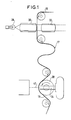
- a cinematographic projector allows the projection of a film 16 which is unwound from an input coil not shown and which is rewound on an output coil also not shown.
- the projector performs two functions simultaneously. It projects images on a screen and provides amplifiers and speakers with two electrical signals representative of stereophonic sound.
- the film therefore has a main strip for images and two auxiliary strips on the same side of the main strip for sound. To simplify the presentation, we will consider below that there is only one such band called soundtrack.
- the film first passes in front of a powerful projection lamp 28 which illuminates an image of it via a condenser 30.
- the light transmitted through this recorded image is projected by a lens 32 on a projection screen not shown.
- the film is driven discontinuously, image by image, by a drive device, not shown. It then forms a loop of cyclically variable length 17 allowing it to be then driven continuously on a reading drum 20 by a pick-up roller 36 (fig.4), this to allow the soundtrack to be played.
- the drum 20, which rotates about an axis 22 parallel to said transverse direction, has in this direction a width less than that of the film so as not to prevent light from passing through the soundtrack.
- a photoelectric cell 34 On a longitudinally front side of the film, in the immediate vicinity of the latter and of the drum 20, facing the soundtrack, is a photoelectric cell 34 having a sensitive surface 35 for receiving the fraction of an illumination light which passed through this soundtrack, and to provide in response said read signal.
- This signal is representative of the sound which corresponds to the images projected at the same instant.
- the lighting light in question is directed onto the film in the form of a reading beam 40, by a removable lighting head comprising a frame 14 whose general shape is that of a hollow truncated cone of revolution at longitudinal axis 42 coincides with that of the beam 40.
- This frame roughly follows the shape of the reading beam 40 in its rear part inside this frame. It extends forward from its small base, by a short tubular fastening structure with longitudinal generatrices 25 which slides with gentle friction in a circular lighting opening. This opening is formed in a thick support wall 27 forming part of the main frame of the projector. It is opposite the photoelectric cell 34.
- Means for fixing and adjusting the position of the frame are provided. They are symbolically represented in FIG.
- the lighting light is monochromatic and coherent. It is emitted, in the form of a primary beam 3 of wavelength 0.78 micrometer for example, by a laser diode 4 which is carried at the rear of the frame 14 and forms part of the rear assembly previously mentioned 2, 4.
- This diode is supplied and regulated from a housing 5. It would be modulated from this same housing in the case of a writing device. It is mounted so that it can undergo a position adjustment. It provides a beam with low divergence of substantially point origin. This beam is directed forward and reflected by a plane deflection mirror 12 carried at the front of the frame 14 to form the incident beam 9 previously mentioned.
- This mirror is arranged so that the virtual point origin 8 of this incident beam is, possibly after adjusting the position of the diode 4, located on a reading line 6 aligned along a generatrix of the drum 20 opposite the sensitive surface 35 of cell 34.
- this reading line is the extension of a transverse line of the section of the film whose main strip is in abutment on the drum 20.
- the part of this line which extends over the width of the soundtrack constitutes the elongated reading window previously mentioned.
- the planar shape of the deflection mirror has the advantage of forming a point virtual image without aberration, while being of simple realization and of low cost.
- the position of the reading window is, of course, adjusted not exactly on a generatrix of the cylindrical surface of the reading drum 20 but on the exposed face of the film 16.
- the incident beam thus formed has a point origin at a finite distance
- an incident beam whose point origin is still located on the same line of reading, but at infinite distance, that is to say that this incident beam would be a parallel beam whose direction would be that of this reading line.
- the reading beam 40 is formed from the incident beam 9 by reflection on a focusing mirror 2 which is carried at the rear of the frame 14.
- the passage of the incident beam is allowed by a wide opening 15 formed for this purpose in the frustoconical wall of the frame 14.
- the mirror 2, or more precisely its reflecting surface constitutes part of a spherical surface whose center 10 is located on the reading line 6 approximately in the middle between the virtual source 8 and the medium of the width of the soundtrack of the film 16. This center 10 constitutes the center of curvature of the mirror 2.
- the essential is only that the focusing mirror is part of a surface of revolution around the reading line. This ensures that any incident light ray comparable to a straight line passing through the point source 8 is reflected by the focusing mirror according to a ray passing exactly through this reading line. This theoretically makes the width of the reading window formed on the film by such rays zero, this width being measured according to the direction of travel of the film.
- the soundtrack must however be lit across its entire width. This is obtained in particular thanks to a suitable choice of the above-mentioned mean angle of inclination.
- This angle 7 can for example be measured from the center 11 of the mirror 2. It extends between the directions going from this center towards the point source 8 and towards the center of curvature 10. It is for example 10 degrees, the angular extent of the incident beam, for example 20 degrees.
Landscapes
- Physics & Mathematics (AREA)
- General Physics & Mathematics (AREA)
- Optical Recording Or Reproduction (AREA)
- Optical Head (AREA)
- Drawing Aids And Blackboards (AREA)
- Camera Data Copying Or Recording (AREA)
- Color Television Image Signal Generators (AREA)
Priority Applications (1)
| Application Number | Priority Date | Filing Date | Title |
|---|---|---|---|
| AT88109665T ATE86768T1 (de) | 1987-06-19 | 1988-06-16 | Lese- ond/oder schreibeinrichtung fuer eine zusatzspur eines kinofilms, insbesondere fuer eine tonspur und beleuchtungsvorrichtung fuer diese einrichtung. |
Applications Claiming Priority (2)
| Application Number | Priority Date | Filing Date | Title |
|---|---|---|---|
| FR8708618A FR2616951B1 (fr) | 1987-06-19 | 1987-06-19 | Dispositif de lecture et/ou ecriture d'une bande auxiliaire d'un film cinematographique, notamment d'une bande son, et tete d'eclairage pour ce dispositif |
| FR8708618 | 1987-06-19 |
Publications (2)
| Publication Number | Publication Date |
|---|---|
| EP0295687A1 true EP0295687A1 (de) | 1988-12-21 |
| EP0295687B1 EP0295687B1 (de) | 1993-03-10 |
Family
ID=9352263
Family Applications (1)
| Application Number | Title | Priority Date | Filing Date |
|---|---|---|---|
| EP88109665A Expired - Lifetime EP0295687B1 (de) | 1987-06-19 | 1988-06-16 | Lese- ond/oder Schreibeinrichtung für eine Zusatzspur eines Kinofilms, insbesondere für eine Tonspur und Beleuchtungsvorrichtung für diese Einrichtung |
Country Status (8)
| Country | Link |
|---|---|
| US (1) | US4942566A (de) |
| EP (1) | EP0295687B1 (de) |
| JP (1) | JP2525226B2 (de) |
| AT (1) | ATE86768T1 (de) |
| CA (1) | CA1328364C (de) |
| DE (1) | DE3878998T2 (de) |
| ES (1) | ES2039507T3 (de) |
| FR (1) | FR2616951B1 (de) |
Families Citing this family (2)
| Publication number | Priority date | Publication date | Assignee | Title |
|---|---|---|---|---|
| DE19521034B4 (de) * | 1995-06-09 | 2005-04-21 | Raytheon Marine Gmbh | Lichttonkopf und Tonfilmprojektor damit |
| US5774174A (en) * | 1996-02-07 | 1998-06-30 | Hardie; Robert Joseph | Laser projector |
Citations (3)
| Publication number | Priority date | Publication date | Assignee | Title |
|---|---|---|---|---|
| DE371528C (de) * | 1921-04-19 | 1923-03-16 | Rudolf Mylo | Verfahren und Einrichtung zur Herstellung von Schallwellenphotogrammen |
| US4149781A (en) * | 1974-01-15 | 1979-04-17 | The United States Of America As Represented By The Secretary Of The Army | Sealed, super 8, optical sound, projection means |
| WO1981001217A1 (en) * | 1979-10-26 | 1981-04-30 | G Bird | Fluorescent soundtrack readout system |
Family Cites Families (5)
| Publication number | Priority date | Publication date | Assignee | Title |
|---|---|---|---|---|
| US3514776A (en) | 1968-05-27 | 1970-05-26 | United Aircraft Corp | Mirror device |
| JPS52130305A (en) * | 1976-04-24 | 1977-11-01 | Chinon Ind Inc | Optically recording signal detector |
| JPS5587329A (en) * | 1978-12-22 | 1980-07-02 | Matsushita Electric Ind Co Ltd | Optical recorder/reproducer |
| IL66817A0 (en) * | 1982-09-16 | 1982-12-31 | Gaz Moshe | Special visual and sound effects in cinematography using beam lasers on positive and negative copies |
| US4603099A (en) * | 1982-11-22 | 1986-07-29 | Drexler Technology Corporation | Method for recording motion picture images and laser written data |
-
1987
- 1987-06-19 FR FR8708618A patent/FR2616951B1/fr not_active Expired
-
1988
- 1988-06-16 ES ES198888109665T patent/ES2039507T3/es not_active Expired - Lifetime
- 1988-06-16 AT AT88109665T patent/ATE86768T1/de not_active IP Right Cessation
- 1988-06-16 DE DE8888109665T patent/DE3878998T2/de not_active Expired - Fee Related
- 1988-06-16 EP EP88109665A patent/EP0295687B1/de not_active Expired - Lifetime
- 1988-06-17 CA CA000569763A patent/CA1328364C/fr not_active Expired - Fee Related
- 1988-06-17 JP JP63149932A patent/JP2525226B2/ja not_active Expired - Lifetime
- 1988-06-20 US US07/208,617 patent/US4942566A/en not_active Expired - Fee Related
Patent Citations (3)
| Publication number | Priority date | Publication date | Assignee | Title |
|---|---|---|---|---|
| DE371528C (de) * | 1921-04-19 | 1923-03-16 | Rudolf Mylo | Verfahren und Einrichtung zur Herstellung von Schallwellenphotogrammen |
| US4149781A (en) * | 1974-01-15 | 1979-04-17 | The United States Of America As Represented By The Secretary Of The Army | Sealed, super 8, optical sound, projection means |
| WO1981001217A1 (en) * | 1979-10-26 | 1981-04-30 | G Bird | Fluorescent soundtrack readout system |
Also Published As
| Publication number | Publication date |
|---|---|
| ES2039507T3 (es) | 1993-10-01 |
| FR2616951B1 (fr) | 1989-09-15 |
| US4942566A (en) | 1990-07-17 |
| JP2525226B2 (ja) | 1996-08-14 |
| DE3878998D1 (de) | 1993-04-15 |
| FR2616951A1 (fr) | 1988-12-23 |
| EP0295687B1 (de) | 1993-03-10 |
| JPS6419540A (en) | 1989-01-23 |
| DE3878998T2 (de) | 1993-06-17 |
| CA1328364C (fr) | 1994-04-12 |
| ATE86768T1 (de) | 1993-03-15 |
Similar Documents
| Publication | Publication Date | Title |
|---|---|---|
| EP0030875B1 (de) | Beleuchtungsvorrichtung für einen grossen Schirm | |
| EP0014609B1 (de) | Vorrichtung zur Bilddarstellung auf einem grossen Bildschirm | |
| FR2487993A1 (fr) | Ensemble d'eclairement artificiel pour appareil photographique et reflecteur pour cet ensemble | |
| EP0015820A1 (de) | Vorrichtung zum berührungslosen und markierungslosen Messen von linearen Geschwindigkeiten | |
| FR2930030A1 (fr) | Dispositif de controle de la qualite d'une surface | |
| EP0374027B1 (de) | Mehrrichtungslaseranemometer | |
| FR2625850A1 (fr) | Appareil optique a laser | |
| FR2460523A1 (fr) | Tete de lecture optique a source laser a semi-conducteur et dispositif de lecture par reflexion d'un support d'information comportant une telle tete optique | |
| EP0295687B1 (de) | Lese- ond/oder Schreibeinrichtung für eine Zusatzspur eines Kinofilms, insbesondere für eine Tonspur und Beleuchtungsvorrichtung für diese Einrichtung | |
| FR2581771A2 (fr) | Appareil de projection et de retroprojection de diapositives avec effet de fondu enchaine | |
| EP2804032A1 (de) | Optische Vorrichtung mit Schnellverschluss | |
| FR2479511A1 (fr) | Perfectionnements aux lecteurs de code electro-optiques | |
| FR2471600A3 (fr) | Dispositif pour le comptage des accidents lumineux survenant dans un materiau de faible epaisseur | |
| EP1831820B1 (de) | Optische biometrikerfassungsvorrichtung mit informationsanzeige für den benutzer | |
| FR2733112A1 (fr) | Televiseur ou moniteur video compact du type a retroprojection | |
| EP0852698B1 (de) | Vibrationskreisel | |
| FR2735245A1 (fr) | Tete de son optique et projecteur pour films sonores ainsi equipe | |
| EP1383316A1 (de) | Ungekühlter optischer Bildaufnahmesensor | |
| CH425265A (fr) | Système optique auto-collimateur | |
| FR2693561A1 (fr) | Source de lumière polarisée et rétroprojecteur utilisant cette source. | |
| WO1997038352A1 (fr) | Dispositif de repartition de lumiere sur un support d'image | |
| WO1992006398A1 (fr) | Dispositif de prise de vue et de projection | |
| FR2645263A1 (fr) | Capteur de position optique pour gyrometre a laser | |
| FR2642836A1 (fr) | Capteur de deplacement | |
| FR2645261A1 (fr) | Dispositif de melange et de lecture pour gyrometre a laser |
Legal Events
| Date | Code | Title | Description |
|---|---|---|---|
| PUAI | Public reference made under article 153(3) epc to a published international application that has entered the european phase |
Free format text: ORIGINAL CODE: 0009012 |
|
| AK | Designated contracting states |
Kind code of ref document: A1 Designated state(s): AT BE CH DE ES FR GB GR IT LI LU NL SE |
|
| 17P | Request for examination filed |
Effective date: 19890605 |
|
| RAP1 | Party data changed (applicant data changed or rights of an application transferred) |
Owner name: GODARD, BRUNO Owner name: ALCATEL ALSTHOM COMPAGNIE GENERALE D'ELECTRICITE |
|
| 17Q | First examination report despatched |
Effective date: 19910814 |
|
| GRAA | (expected) grant |
Free format text: ORIGINAL CODE: 0009210 |
|
| AK | Designated contracting states |
Kind code of ref document: B1 Designated state(s): AT BE CH DE ES FR GB GR IT LI LU NL SE |
|
| REF | Corresponds to: |
Ref document number: 86768 Country of ref document: AT Date of ref document: 19930315 Kind code of ref document: T |
|
| REF | Corresponds to: |
Ref document number: 3878998 Country of ref document: DE Date of ref document: 19930415 |
|
| GBT | Gb: translation of ep patent filed (gb section 77(6)(a)/1977) |
Effective date: 19930323 |
|
| ITF | It: translation for a ep patent filed | ||
| REG | Reference to a national code |
Ref country code: GR Ref legal event code: FG4A Free format text: 3007888 |
|
| REG | Reference to a national code |
Ref country code: ES Ref legal event code: FG2A Ref document number: 2039507 Country of ref document: ES Kind code of ref document: T3 |
|
| PLBE | No opposition filed within time limit |
Free format text: ORIGINAL CODE: 0009261 |
|
| STAA | Information on the status of an ep patent application or granted ep patent |
Free format text: STATUS: NO OPPOSITION FILED WITHIN TIME LIMIT |
|
| 26N | No opposition filed | ||
| EPTA | Lu: last paid annual fee | ||
| EAL | Se: european patent in force in sweden |
Ref document number: 88109665.5 |
|
| PGFP | Annual fee paid to national office [announced via postgrant information from national office to epo] |
Ref country code: GB Payment date: 19990511 Year of fee payment: 12 |
|
| PGFP | Annual fee paid to national office [announced via postgrant information from national office to epo] |
Ref country code: FR Payment date: 19990512 Year of fee payment: 12 |
|
| PGFP | Annual fee paid to national office [announced via postgrant information from national office to epo] |
Ref country code: CH Payment date: 19990514 Year of fee payment: 12 |
|
| PGFP | Annual fee paid to national office [announced via postgrant information from national office to epo] |
Ref country code: AT Payment date: 19990521 Year of fee payment: 12 |
|
| PGFP | Annual fee paid to national office [announced via postgrant information from national office to epo] |
Ref country code: SE Payment date: 19990525 Year of fee payment: 12 Ref country code: DE Payment date: 19990525 Year of fee payment: 12 |
|
| PGFP | Annual fee paid to national office [announced via postgrant information from national office to epo] |
Ref country code: NL Payment date: 19990527 Year of fee payment: 12 |
|
| PGFP | Annual fee paid to national office [announced via postgrant information from national office to epo] |
Ref country code: LU Payment date: 19990528 Year of fee payment: 12 |
|
| PGFP | Annual fee paid to national office [announced via postgrant information from national office to epo] |
Ref country code: GR Payment date: 19990610 Year of fee payment: 12 |
|
| PGFP | Annual fee paid to national office [announced via postgrant information from national office to epo] |
Ref country code: BE Payment date: 19990614 Year of fee payment: 12 |
|
| PGFP | Annual fee paid to national office [announced via postgrant information from national office to epo] |
Ref country code: ES Payment date: 19990714 Year of fee payment: 12 |
|
| PG25 | Lapsed in a contracting state [announced via postgrant information from national office to epo] |
Ref country code: LU Free format text: LAPSE BECAUSE OF NON-PAYMENT OF DUE FEES Effective date: 20000616 Ref country code: GB Free format text: LAPSE BECAUSE OF NON-PAYMENT OF DUE FEES Effective date: 20000616 Ref country code: AT Free format text: LAPSE BECAUSE OF NON-PAYMENT OF DUE FEES Effective date: 20000616 |
|
| PG25 | Lapsed in a contracting state [announced via postgrant information from national office to epo] |
Ref country code: SE Free format text: LAPSE BECAUSE OF NON-PAYMENT OF DUE FEES Effective date: 20000617 Ref country code: ES Free format text: THE PATENT HAS BEEN ANNULLED BY A DECISION OF A NATIONAL AUTHORITY Effective date: 20000617 |
|
| PG25 | Lapsed in a contracting state [announced via postgrant information from national office to epo] |
Ref country code: LI Free format text: LAPSE BECAUSE OF NON-PAYMENT OF DUE FEES Effective date: 20000630 Ref country code: GR Free format text: LAPSE BECAUSE OF NON-PAYMENT OF DUE FEES Effective date: 20000630 Ref country code: CH Free format text: LAPSE BECAUSE OF NON-PAYMENT OF DUE FEES Effective date: 20000630 Ref country code: BE Free format text: LAPSE BECAUSE OF NON-PAYMENT OF DUE FEES Effective date: 20000630 |
|
| BERE | Be: lapsed |
Owner name: GODARD BRUNO Effective date: 20000630 Owner name: ALCATEL ALSTHOM CIE GENERALE D'ELECTRICITE Effective date: 20000630 |
|
| PG25 | Lapsed in a contracting state [announced via postgrant information from national office to epo] |
Ref country code: NL Free format text: LAPSE BECAUSE OF NON-PAYMENT OF DUE FEES Effective date: 20010101 |
|
| GBPC | Gb: european patent ceased through non-payment of renewal fee |
Effective date: 20000616 |
|
| REG | Reference to a national code |
Ref country code: CH Ref legal event code: PL |
|
| EUG | Se: european patent has lapsed |
Ref document number: 88109665.5 |
|
| PG25 | Lapsed in a contracting state [announced via postgrant information from national office to epo] |
Ref country code: FR Free format text: LAPSE BECAUSE OF NON-PAYMENT OF DUE FEES Effective date: 20010228 |
|
| NLV4 | Nl: lapsed or anulled due to non-payment of the annual fee |
Effective date: 20010101 |
|
| REG | Reference to a national code |
Ref country code: FR Ref legal event code: ST |
|
| PG25 | Lapsed in a contracting state [announced via postgrant information from national office to epo] |
Ref country code: DE Free format text: LAPSE BECAUSE OF NON-PAYMENT OF DUE FEES Effective date: 20010403 |
|
| REG | Reference to a national code |
Ref country code: ES Ref legal event code: FD2A Effective date: 20020204 |
|
| PG25 | Lapsed in a contracting state [announced via postgrant information from national office to epo] |
Ref country code: IT Free format text: LAPSE BECAUSE OF NON-PAYMENT OF DUE FEES;WARNING: LAPSES OF ITALIAN PATENTS WITH EFFECTIVE DATE BEFORE 2007 MAY HAVE OCCURRED AT ANY TIME BEFORE 2007. THE CORRECT EFFECTIVE DATE MAY BE DIFFERENT FROM THE ONE RECORDED. Effective date: 20050616 |