EP0297271A2 - Station d'inspection de feuilles avec guidage pneumatique de la feuille - Google Patents
Station d'inspection de feuilles avec guidage pneumatique de la feuille Download PDFInfo
- Publication number
- EP0297271A2 EP0297271A2 EP88108116A EP88108116A EP0297271A2 EP 0297271 A2 EP0297271 A2 EP 0297271A2 EP 88108116 A EP88108116 A EP 88108116A EP 88108116 A EP88108116 A EP 88108116A EP 0297271 A2 EP0297271 A2 EP 0297271A2
- Authority
- EP
- European Patent Office
- Prior art keywords
- sheet
- air
- sensor package
- inspection station
- directing
- Prior art date
- Legal status (The legal status is an assumption and is not a legal conclusion. Google has not performed a legal analysis and makes no representation as to the accuracy of the status listed.)
- Withdrawn
Links
Images


Classifications
-
- B—PERFORMING OPERATIONS; TRANSPORTING
- B65—CONVEYING; PACKING; STORING; HANDLING THIN OR FILAMENTARY MATERIAL
- B65H—HANDLING THIN OR FILAMENTARY MATERIAL, e.g. SHEETS, WEBS, CABLES
- B65H23/00—Registering, tensioning, smoothing or guiding webs
- B65H23/04—Registering, tensioning, smoothing or guiding webs longitudinally
- B65H23/24—Registering, tensioning, smoothing or guiding webs longitudinally by fluid action, e.g. to retard the running web
-
- G—PHYSICS
- G01—MEASURING; TESTING
- G01N—INVESTIGATING OR ANALYSING MATERIALS BY DETERMINING THEIR CHEMICAL OR PHYSICAL PROPERTIES
- G01N21/00—Investigating or analysing materials by the use of optical means, i.e. using sub-millimetre waves, infrared, visible or ultraviolet light
- G01N21/84—Systems specially adapted for particular applications
- G01N21/88—Investigating the presence of flaws or contamination
- G01N21/89—Investigating the presence of flaws or contamination in moving material, e.g. running paper or textiles
-
- G—PHYSICS
- G01—MEASURING; TESTING
- G01N—INVESTIGATING OR ANALYSING MATERIALS BY DETERMINING THEIR CHEMICAL OR PHYSICAL PROPERTIES
- G01N33/00—Investigating or analysing materials by specific methods not covered by groups G01N1/00 - G01N31/00
- G01N33/34—Paper
- G01N33/346—Paper sheets
-
- B—PERFORMING OPERATIONS; TRANSPORTING
- B65—CONVEYING; PACKING; STORING; HANDLING THIN OR FILAMENTARY MATERIAL
- B65H—HANDLING THIN OR FILAMENTARY MATERIAL, e.g. SHEETS, WEBS, CABLES
- B65H2406/00—Means using fluid
- B65H2406/10—Means using fluid made only for exhausting gaseous medium
- B65H2406/11—Means using fluid made only for exhausting gaseous medium producing fluidised bed
- B65H2406/112—Means using fluid made only for exhausting gaseous medium producing fluidised bed for handling material along preferably rectilinear path, e.g. nozzle bed for web
-
- G—PHYSICS
- G01—MEASURING; TESTING
- G01B—MEASURING LENGTH, THICKNESS OR SIMILAR LINEAR DIMENSIONS; MEASURING ANGLES; MEASURING AREAS; MEASURING IRREGULARITIES OF SURFACES OR CONTOURS
- G01B2210/00—Aspects not specifically covered by any group under G01B, e.g. of wheel alignment, caliper-like sensors
- G01B2210/40—Caliper-like sensors
- G01B2210/44—Caliper-like sensors with detectors on both sides of the object to be measured
Definitions
- This invention relates to sheet inspection stations used in the manufacture of continuous-sheet materials such as papers, plastics, foils, and the like. More particularly, it relates to the means by which the sheet of material is guided through the inspection station. Yet more particularly, it concerns sheet inspection stations and associated processes employing pneumatic means for guiding the sheet through the inspection station in non-contacting fashion.
- Continuous-manufacturing processes employ measurement and control systems to derive material savings and enhance quality control.
- sheet inspection stations are used to continuously monitor certain physical properties of a material which is being continuously produced in sheet form.
- These inspection stations employ one or more measurement sensors.
- these sensors are collectively referred to as a "sensor package”.
- the sensor package is mounted usually through a carriage or sheet traversing mechanism on a conventional frame.
- the frame typically houses a drive system that enables movement of the carriage, with the sensor package, back and forth across the sheet of material so that measurement of the relevant physical properties can be made across the entire cross-machine width of the sheet.
- the sensors making up the sensor package are technically sophisticated apparatus that typically employ a source of electromagnetic radiation in conjunction with a radiation detection device in order to produce electrical output signals, the magnitudes of which vary according to the degree of interaction of the radiation with one or more constituents of the sheet. These output signals are delivered to a remote signal processing unit such as a digital computer, where they are appropriately processed to produce measurements of the physical properties of interest.
- a remote signal processing unit such as a digital computer
- This invention provides a sheet inspection station that eliminates measurement error resulting from fiber/dust buildup associated with friction between conventional guide rails and the sheet. In addition, the invention eliminates the need for periodic replacement of guide rails which are worn flat from continuous contact with the sheet.
- the present invention provides sheet inspection stations and associated processes that employ pneumatic means for guiding a sheet of material past a sensor package in non-contacting fashion.
- the invention thus eliminates measurement error resulting from the buildup of fiber or dust created by continuous contact of the sheet with conventional guide rails.
- the invention directs streams of air onto the sheet at four different machine-direction positions. Two of these positions are upstream from the sensor package and the streams of air directed thereat cooperate to orient the sheet in accordance with a desired path of motion and guide the sheet into a housing in which the sensor package is contained. The remaining two positions are downstream from the sensor package and the streams of air directed thereat cooperate to maintain the desired orientation of the sheet and guide the sheet out from the housing. The sheet is thus guided past the sensor package in non-contacting fashion.
- the streams of air collectively cooperate to effect a slight increase in tension of the sheet over a range which includes the sensor package.
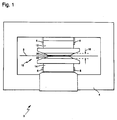
- the numeral 2 designates a sheet of material that is in motion during its continuous production. An edge view of the entire cross-machine width of the sheet 2 is indicated.
- the sheet 2 is illustrated as passing through a sheet inspection station, (designated generally by the numeral 3), and may be viewed as moving into the drawing.
- the sheet inspection station 3 includes a conventional frame 4 to which a carriage mechanism comprising an upper carriage member 6 and a lower carriage member 8 is movably secured.
- the carriage mechanism is mechanically responsive to motion produced by a drive system (not shown) contained in the frame 4.
- the upper and lower carriage members 6, 8 move together across the sheet 2 to one extreme thereof, and then move back across the sheet to the opposite extreme.
- This reciprocating motion hereinafter referred to as "scanning" continues during production of the sheet material, and is effected in a known manner by the drive system.
- Housing for a sensor package is indicated generally by the numeral 10 and includes an upper housing 12 rigidly secured to the upper carriage member 6, and a lower housing 14 rigidly secured to the lower carriage member 8.
- the desired path of motion for the sheet 2 is through a pass gap 16 separating the upper and lower housings 12, 14.
- the housing 10 contains a sensor package comprising at least one, but typically plural sensors or gauges adapted to produce electrical signals indicative of one or more physical properties of the sheet 2. These sensors may have both upper and lower portions that are aligned and located in the upper and lower housings 12, 14, respectively, or may have a single portion located in either the upper or lower housing.
- a sensor package is represented by a dashed line 15 enclosing upper portions of three sensors 16, 17, 18.
- a cross-machine width 19 of the sensor package 15 is defined by the maximum range over which the sensors extend in the cross-machine direction.
- pneumatic means for guiding the sheet 2 past the sensor package 15 includes four air-directing components 20, 22, 24, 26 located between the housing 10 and the sensor package 15. Air is directed from each of these components onto the sheet 2. In contrast with conventional guide rails, (See, e.g. those designated with the numeral 23 in Fig. 2.), the air-directing components 20, 22, 24, 26 do not contact the sheet 2 during normal operation.
- the components are oriented with respect to the sensor package 15 to direct the sheet 2 through the pass gap 16.
- the components are positioned to direct air over a portion of the sheet width which includes the entire cross-machine width 19 of the sensor package 15.
- Components 20 and 24 are secured to the upper carriage member 6, and components 22 and 26 are secured to the lower carriage member 8 as hereinafter described.
- Components 20 and 22 form a first pair 21 of air-directing components for guiding the sheet 2 into the housing 10.
- Components 24 and 26 form a second pair 25 of air-directing components for guiding the sheet 2 out from the housing 10.
- Air-regulated air is supplied to the air-directing components 20, 22, 24, 26 from a remote source, (not shown), and conventional flow regulating means 28, 30 are provided as indicated in Figure 5. Since air-directing components 22 and 26 must overcome the local weight of the sheet 2 to form air bearings, they can be expected to require higher flow rates than will be required for air-directing components 20 and 24. Accordingly, it is preferred that components 22 and 26 be in fluid communication with a common flow regulating means 28 while components 20 and 24 be in fluid communication with a second common flow regulating means 30.
- components 20 and 24 are secured to the upper carriage member 6, and components 22 and 26 are secured to the lower carriage member 8. This is done in the manner shown for component 20 in Fig. 4, and is similar to the manner in which the sensors 16, 17, 18 are secured to the carriage mechanism.
- rods 32, 34 having flattened ends are fitted and secured in slots 37 (Fig. 6) formed in each end of the component 20.
- the rods 32, 34 are slidably disposed within bores 38, 39 formed in slotted guide mounts 40, 42.
- the clearance between component 20 and its pair-counterpart (component 22) is thus adjustable by movement of the rods 32, 34 within their respective bores or by movement of similar rods for the pair-counterpart.
- the clearance is fixed via set-screws (as at 44).
- the guide mounts 40, 42 slide over square rails 46, 48 attached to interior surfaces of the upper housing 12, and are secured to the housing through threaded bores 50, 52.
- the upper housing 12 is bolted to the upper carriage member 6 (Fig. 1) through holes (as at 54, 56) which are arranged to provide for adjustment of the pass angle.
- Component 24 is secured to the opposite end of the upper carriage member 6 in similar fashion and components 22 and 26 are likewise secured to the lower carriage member 8.
- the above-described mounting arrangement for the air-directing components 20, 22, 24, 26 is one of many possible arrangements, and the arrangement used is not seen as particularly important in the practice of this invention, although the feature of adjustable clearance between the components of each pair is seen as important in minimizing the air flow required to form air bearings between the sheet 2 and each component.
- the clearance may be positive, near zero (See, e.g. Fig. 5), or even slightly negative depending on the physical characteristics of the sheet 2.
- each air-directing component may be positioned differently, as determined along the machine direction, from the air-directing component of the same pair.
- two vertical bores (as at 38 and 57) are provided in each guide mount.
- any air-directing component may be inserted in either of two positions.
- the sheet 2 travels in the machine direction indicated by the arrow 58.
- the first pair 21 of components is upstream from the sensor package 15 (Fig. 3), and the second pair 25 is downstream from the sensor package.
- the air-directing components of each pair 21, 25 are in different machine-direction positions as indicated.
- This difference in machine-direction positions is provided to increase sheet stability by maintaining slight tension on the sheet 2 over a range extending between the two pairs 21, 25. In addition to minimizing sheet flutter, this facilitates guiding the sheet 2 into and out from the housing 10 (Fig. 1).
- streams of air continuously directed from four locations corresponding to components 20, 22, 24 and 26 impinge the sheet 2 at four machine-direction positions.
- Components 20 and 24 direct streams of air onto a first surface 60 corresponding to the top of the sheet 2 to urge the sheet away from the components.
- components 22 and 26 which face generally a direction opposite that faced by their pair-counterparts, direct streams of air onto a second surface 62 corresponding to the bottom of the sheet to urge the sheet away from these components.
- Arrows 64 and 66 indicate the approximate center positions of displacement ranges 68 and 70, respectively. It will be recognized from the drawing that the components of each pair 21, 25 cooperate to exert a slight rotation of the sheet 2 about positions 64 and 66, respectively. The rotation about position 64 is in a direction opposite the rotation about point 66. The two pairs 21, 25 thus cooperate to produce an increase in tension of the sheet over a range extending between the center positions 64, 66.
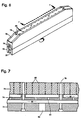
- the current design is shown in Figs. 5 and 6 and comprises a base section 72, a staging section 74, and a delivery section 76.
- a channel is cut in the staging section 74 to accommodate the delivery section 76.
- the three sections 72, 74, 76 are secured with bolts extending through threaded bores (as at 78).
- An interior channel in the base section 72 is milled from the surface facing the staging section 74 to form a main plenum 80. Air flows into the main plenum 80 via a threaded supply bore 82.
- a plurality of separate interior channels of the staging section 74 are milled from the surface facing the delivery section 76 to form a plurality of staging plenums (as at 84).
- the machine-direction width of the staging plenums 84 is substantially the same as that of the delivery section 76.
- At least one hole (as at 86) is drilled in the staging section 74 for each staging plenum 84 to provide a flow channel between the main plenum 80 and each staging plenum.
- a plurality of V-notches are cut along hidden surfaces of the delivery section 76 to provide air delivery from the staging plenums 84 to the sheet 2.
- the staging plenums 84 are provided in anticipation of difficulty in maintaining air bearings when a portion of the pneumatic sheet-guiding means is "off-sheet". Thus, they are unnecessary in the case of non-scanning sensor packages, and may prove unnecessary in any event. Moreover, where the aperture or apertures (e.g. the V-notches of Figs. 5 and 6) can be sized to provide the required air bearings at a flow rate which is near saturation, any effect from off-sheet positioning should be negligible.
- the invention can be used by replacing the second pair 25 of air-directing components 24, 26 with conventional guide rails, and most of the advantages provided by the invention will still be realized since guide rails positioned downstream from the sensor package 15 do not contribute as heavily to the dust buildup problem as those positioned upstream from the sensor package.
- the pneumatic sheet guiding means be located inside the housing 10, although such a location is preferable for both practical and aesthetic reasons.
- the invention be restricted to scanning sensor packages, or to sensor packages having both upper and lower portions, and those skilled in the art will recognize that the invention can easily be adapted for other embodiments.
Landscapes
- Health & Medical Sciences (AREA)
- Life Sciences & Earth Sciences (AREA)
- Chemical & Material Sciences (AREA)
- Pathology (AREA)
- Physics & Mathematics (AREA)
- Analytical Chemistry (AREA)
- Biochemistry (AREA)
- General Health & Medical Sciences (AREA)
- General Physics & Mathematics (AREA)
- Immunology (AREA)
- Engineering & Computer Science (AREA)
- Food Science & Technology (AREA)
- Medicinal Chemistry (AREA)
- Textile Engineering (AREA)
- Treatment Of Fiber Materials (AREA)
- Length Measuring Devices With Unspecified Measuring Means (AREA)
Applications Claiming Priority (2)
| Application Number | Priority Date | Filing Date | Title |
|---|---|---|---|
| US5602587A | 1987-06-01 | 1987-06-01 | |
| US56025 | 1987-06-01 |
Publications (2)
| Publication Number | Publication Date |
|---|---|
| EP0297271A2 true EP0297271A2 (fr) | 1989-01-04 |
| EP0297271A3 EP0297271A3 (fr) | 1989-07-26 |
Family
ID=22001679
Family Applications (1)
| Application Number | Title | Priority Date | Filing Date |
|---|---|---|---|
| EP88108116A Withdrawn EP0297271A3 (fr) | 1987-06-01 | 1988-05-20 | Station d'inspection de feuilles avec guidage pneumatique de la feuille |
Country Status (3)
| Country | Link |
|---|---|
| EP (1) | EP0297271A3 (fr) |
| CA (1) | CA1291243C (fr) |
| FI (1) | FI882566A7 (fr) |
Cited By (4)
| Publication number | Priority date | Publication date | Assignee | Title |
|---|---|---|---|---|
| DE19525779A1 (de) * | 1995-07-13 | 1997-01-16 | Siemens Ag | Verfahren zur Bestimmung der mechanischen Eigenschaften von Papier und Anordnung zur Durchführung des Verfahrens |
| US6091501A (en) * | 1998-07-14 | 2000-07-18 | Neles Automation Oy | Method of keeping measuring window of measuring device clean, and measuring device |
| WO2004000708A1 (fr) * | 2002-06-24 | 2003-12-31 | Nextrom Holding S.A. | Dispositif dans un processus de traitement de fibre |
| EP1621883A3 (fr) * | 2004-07-08 | 2006-06-07 | LSC Process- und Laborsysteme GmbH | Dispositif d'inspection d'une bande de matériau |
Families Citing this family (1)
| Publication number | Priority date | Publication date | Assignee | Title |
|---|---|---|---|---|
| CN110927081B (zh) * | 2019-11-06 | 2022-05-10 | 华为技术有限公司 | 一种气体浓度检测装置、电子设备及方法 |
Family Cites Families (4)
| Publication number | Priority date | Publication date | Assignee | Title |
|---|---|---|---|---|
| US3552203A (en) * | 1967-11-13 | 1971-01-05 | Industrial Nucleonics Corp | System for and method of measuring sheet properties |
| US4201323A (en) * | 1978-10-12 | 1980-05-06 | W. R. Grace & Co. | High velocity web floating air bar having a recessed Coanda plate |
| US4319847A (en) * | 1979-12-05 | 1982-03-16 | Measurex Corporation | Apparatus to measure select properties of a moving sheet with improved standardization means |
| US4786817A (en) * | 1986-08-29 | 1988-11-22 | Measurex Corporation | System and method for measurement of traveling webs |
-
1988
- 1988-05-20 EP EP88108116A patent/EP0297271A3/fr not_active Withdrawn
- 1988-05-24 CA CA000567504A patent/CA1291243C/fr not_active Expired
- 1988-05-31 FI FI882566A patent/FI882566A7/fi not_active Application Discontinuation
Cited By (5)
| Publication number | Priority date | Publication date | Assignee | Title |
|---|---|---|---|---|
| DE19525779A1 (de) * | 1995-07-13 | 1997-01-16 | Siemens Ag | Verfahren zur Bestimmung der mechanischen Eigenschaften von Papier und Anordnung zur Durchführung des Verfahrens |
| US6091501A (en) * | 1998-07-14 | 2000-07-18 | Neles Automation Oy | Method of keeping measuring window of measuring device clean, and measuring device |
| WO2004000708A1 (fr) * | 2002-06-24 | 2003-12-31 | Nextrom Holding S.A. | Dispositif dans un processus de traitement de fibre |
| CN100341758C (zh) * | 2002-06-24 | 2007-10-10 | 奈克斯特罗姆·霍尔丁公司 | 纤维处理设备 |
| EP1621883A3 (fr) * | 2004-07-08 | 2006-06-07 | LSC Process- und Laborsysteme GmbH | Dispositif d'inspection d'une bande de matériau |
Also Published As
| Publication number | Publication date |
|---|---|
| FI882566A0 (fi) | 1988-05-31 |
| EP0297271A3 (fr) | 1989-07-26 |
| CA1291243C (fr) | 1991-10-22 |
| FI882566L (fi) | 1988-12-02 |
| FI882566A7 (fi) | 1988-12-02 |
Similar Documents
| Publication | Publication Date | Title |
|---|---|---|
| US4877485A (en) | Sheet inspection station with pneumatic sheet guide | |
| EP1436569B1 (fr) | Systeme et procede de detection de feuille sans contact | |
| EP1273879B1 (fr) | Méthode et appareil pour mesurer au moins une propriété d'une bande en mouvement | |
| US3528002A (en) | Caliper with air bearings for continuously moving sheet material | |
| US4955720A (en) | On-line fiber orientation distribution measurement | |
| US8083895B2 (en) | Sheet stabilization with dual opposing cross direction air clamps | |
| EP2091854B1 (fr) | Appareil et procédé permettant la stabilisation d'une feuille mobile par rapport à un capteur | |
| US5226577A (en) | Web guide for elongated flexible web | |
| US6640391B2 (en) | Pressure regulating device for use on a carding machine | |
| US7296717B2 (en) | Method and apparatus for controlling a moving web | |
| US6431778B1 (en) | Device for symbol printing and franking machine comprising same | |
| CA1291243C (fr) | Poste de controle de feuilles a guide-feuilles pneumatique | |
| US5613790A (en) | Apparatus for normalizing top-of-form registration in a moving web printer | |
| EP0389265B1 (fr) | Jauge d'épaisseur pour matériau en feuille en mouvement | |
| US4373993A (en) | Slice lip forming a smooth continuous surface | |
| JPH08225333A (ja) | 板ガラスの切断方法及び装置 | |
| US5745244A (en) | Scanning device for scanning a physical property of a fibrous web | |
| US5191222A (en) | Apparatus for synchronizing data reading capabilities of an optical reader | |
| US6494081B1 (en) | Method of measuring properties of paper, and arrangement in a paper measuring apparatus | |
| US4516446A (en) | Precision rotating rod guide | |
| US20040070646A1 (en) | Image forming apparatus | |
| EP0133818A1 (fr) | Machines pour l'alimentation en feuilles | |
| JPH02305751A (ja) | ループ量制御装置 | |
| FI110639B (fi) | Menetelmä paperin ominaisuuksien mittaamiseksi ja mittalaite | |
| SE508873C2 (sv) | Anordning vid mätstation |
Legal Events
| Date | Code | Title | Description |
|---|---|---|---|
| PUAI | Public reference made under article 153(3) epc to a published international application that has entered the european phase |
Free format text: ORIGINAL CODE: 0009012 |
|
| AK | Designated contracting states |
Kind code of ref document: A2 Designated state(s): DE FR GB IT SE |
|
| PUAL | Search report despatched |
Free format text: ORIGINAL CODE: 0009013 |
|
| AK | Designated contracting states |
Kind code of ref document: A3 Designated state(s): DE FR GB IT SE |
|
| 17P | Request for examination filed |
Effective date: 19891219 |
|
| RAP1 | Party data changed (applicant data changed or rights of an application transferred) |
Owner name: ABB PROCESS AUTOMATION INC. |
|
| 17Q | First examination report despatched |
Effective date: 19911017 |
|
| STAA | Information on the status of an ep patent application or granted ep patent |
Free format text: STATUS: THE APPLICATION IS DEEMED TO BE WITHDRAWN |
|
| 18D | Application deemed to be withdrawn |
Effective date: 19940215 |