EP0297668A2 - Verfahren zum Bedrucken plattenförmiger Informationsträger - Google Patents
Verfahren zum Bedrucken plattenförmiger Informationsträger Download PDFInfo
- Publication number
- EP0297668A2 EP0297668A2 EP88201322A EP88201322A EP0297668A2 EP 0297668 A2 EP0297668 A2 EP 0297668A2 EP 88201322 A EP88201322 A EP 88201322A EP 88201322 A EP88201322 A EP 88201322A EP 0297668 A2 EP0297668 A2 EP 0297668A2
- Authority
- EP
- European Patent Office
- Prior art keywords
- information
- printing
- printer
- information carrier
- label information
- Prior art date
- Legal status (The legal status is an assumption and is not a legal conclusion. Google has not performed a legal analysis and makes no representation as to the accuracy of the status listed.)
- Granted
Links
Images

Classifications
-
- G—PHYSICS
- G06—COMPUTING OR CALCULATING; COUNTING
- G06V—IMAGE OR VIDEO RECOGNITION OR UNDERSTANDING
- G06V10/00—Arrangements for image or video recognition or understanding
- G06V10/88—Image or video recognition using optical means, e.g. reference filters, holographic masks, frequency domain filters or spatial domain filters
-
- G—PHYSICS
- G06—COMPUTING OR CALCULATING; COUNTING
- G06K—GRAPHICAL DATA READING; PRESENTATION OF DATA; RECORD CARRIERS; HANDLING RECORD CARRIERS
- G06K1/00—Methods or arrangements for marking the record carrier in digital fashion
- G06K1/12—Methods or arrangements for marking the record carrier in digital fashion otherwise than by punching
- G06K1/121—Methods or arrangements for marking the record carrier in digital fashion otherwise than by punching by printing code marks
-
- B—PERFORMING OPERATIONS; TRANSPORTING
- B41—PRINTING; LINING MACHINES; TYPEWRITERS; STAMPS
- B41J—TYPEWRITERS; SELECTIVE PRINTING MECHANISMS, i.e. MECHANISMS PRINTING OTHERWISE THAN FROM A FORME; CORRECTION OF TYPOGRAPHICAL ERRORS
- B41J19/00—Character- or line-spacing mechanisms
- B41J19/16—Special spacing mechanisms for circular, spiral, or diagonal-printing apparatus
-
- B—PERFORMING OPERATIONS; TRANSPORTING
- B41—PRINTING; LINING MACHINES; TYPEWRITERS; STAMPS
- B41J—TYPEWRITERS; SELECTIVE PRINTING MECHANISMS, i.e. MECHANISMS PRINTING OTHERWISE THAN FROM A FORME; CORRECTION OF TYPOGRAPHICAL ERRORS
- B41J3/00—Typewriters or selective printing or marking mechanisms characterised by the purpose for which they are constructed
- B41J3/407—Typewriters or selective printing or marking mechanisms characterised by the purpose for which they are constructed for marking on special material
- B41J3/4071—Printing on disk-shaped media, e.g. CDs
-
- G—PHYSICS
- G11—INFORMATION STORAGE
- G11B—INFORMATION STORAGE BASED ON RELATIVE MOVEMENT BETWEEN RECORD CARRIER AND TRANSDUCER
- G11B23/00—Record carriers not specific to the method of recording or reproducing; Accessories, e.g. containers, specially adapted for co-operation with the recording or reproducing apparatus ; Intermediate mediums; Apparatus or processes specially adapted for their manufacture
- G11B23/38—Visual features other than those contained in record tracks or represented by sprocket holes the visual signals being auxiliary signals
- G11B23/40—Identifying or analogous means applied to or incorporated in the record carrier and not intended for visual display simultaneously with the playing-back of the record carrier, e.g. label, leader, photograph
Definitions
- the invention relates to a method for printing plate-shaped information carriers with label information in the form of graphics and / or writing, which is applied to at least one side of the information carrier in at least one partial area thereof.
- so-called label information is attached to plate-shaped information carriers, which, among other things, provides information about the information content of the information carrier.
- the label information generally contains both writing and graphics.
- the label information is provided on one side of the information carrier in a wide, annular region which is arranged concentrically to the center hole.
- This label information is applied by known methods in a screen printing or in a pad printing process. In both processes, a film must first be produced and then a cliché, the production of which takes time and is time-consuming.
- the known printing processes are inflexible, ie a quick change of different label information for printing Different information carriers are not possible with high machine throughputs. It is practically not possible to individually label each information carrier.
- label information is created by means of a data processing system, the label information is prepared for a printer and passed on to it, and the information carrier is printed by the printer in accordance with this label information.
- Print is understood to mean any device that is suitable for providing the information carrier with a visible identification.
- the method according to the invention for printing plate-shaped information carriers initially offers the advantage that the label information, or at least not all label information, no longer has to be created in an elaborate phototechnical way down to a cliché, but that label information is now possible in a data processing system, for example using a graphics program.
- Such programs are known, for example, for the layout of Production of newspapers and magazines. These programs make it possible to initially create label information in the desired type and form purely electronically in the data processing system. At this stage it is easy to change the label information.
- This label information thus created in the data processing system which is still purely electronic, is then prepared for a printer and forwarded to it.
- the preparation of the label information consists e.g. B. in that this is broken down line by line in the desired structure so that a printer can process it accordingly.
- Such programs are also known in large numbers for printers, for example matrix or inkjet printers in data processing systems.
- Some known printing methods that can be used are e.g. B. described in the journal Computer Design / January 1, 1988, pages 43 to 49, z. B. inkjet printing process, "solid ink print process”, “thermal transfer process”, “type diffusion process”.
- the prepared and forwarded to the printer label information now controls the printer, which prints the information carrier with the label information.
- the creation of label information in a data processing system is quickly possible using a suitable program.
- a change is also possible quickly during the creation process as well as later.
- Various label information for plate-shaped information carriers with different information content can be created in the data processing system.
- a file of various label information can thus be created, from which the desired label information can be called up very quickly and applied to the information carrier by means of the printer. It is thus possible to switch quickly between different label information when printing on information carriers.
- the process is extremely flexible.
- Programs required for processing the label information in the data processing system such as, for example, graphic programs and programs for processing the information for a printer, are available in large numbers on the market and are usually already provided in data processing systems.
- a print head for printing an annular area of the information carrier, a print head is moved radially over the annular area and the information carrier is rotated.
- the label information created in the data processing system is prepared for the printer by means of a suitable program.
- Such programs are known and work in such a way that the information is broken down into lines which can then be processed one after the other by the printer.
- plate-shaped information carriers are to be provided with a label imprint in an annular area, it is advantageous to design the printer or its printing unit in such a way that the print head is positioned radially above it can move annular region of the information carrier.
- the plate-shaped information carrier is rotated. By a sensible combination of these two movements, it is thus possible to print the plate-shaped information carrier one after the other in the annular region to be printed, line by line, by means of the printer.
- a radially running line is first printed, then the information carrier is rotated further by a certain angle, then the next line is printed, and so on.
- the main advantage here is that the structure of the device to be provided for such printing is simple.
- Another possibility is to continuously rotate the information carrier so that the label information is printed in concentric or spiral tracks. The print head is moved radially accordingly.
- the program must be adapted to this procedure.
- the latter and the print head are each moved on a straight line, both of which run at a right angle to one another.
- Such a method is particularly advantageous in cases where not only a partial area of the information carrier but almost an entire page is to be printed.
- a simple line-by-line decomposition of label information takes place, for example the decomposition for one conventional paper printer is identical.
- the advantage of this method is that programs for processing the information for a printer, which are already available for paper printers, can also be used for printing plate-shaped information carriers.
- an inkjet printer is provided as the printer.
- Inkjet printers are particularly suitable for the method according to the invention because the method works without contact.
- a method is also possible, which is characterized in that for each printing operation a laser-sensitive exposure roller is exposed by a laser in accordance with computer graphics, that the exposed areas are wetted via an ink container and transferred to a printing roller, and that this printing information is transmitted to one over each Transport device introduced information carrier is transmitted. High quality prints are possible with this process.
- the invention also relates to a device for carrying out the latter laser printing method.
- This device is characterized by an exposure roller which can be exposed by a laser and to which an ink container is assigned, and by a printing roller which interacts with the exposure roller and which in turn is arranged in the immediate vicinity of a transport device for the CD disks to be printed.
- an embodiment of the method of the invention is advantageous in many cases if the printed information carrier is provided with a transparent protective layer.
- the method offers the important possibility of providing plate-shaped information carriers of a series with the same information content with individual identifiers. This is of interest, for example, in the case of the so-called CD-ROM disks.
- Individual labeling enables a specific item to be traced, i.e. control over whether the user of this copy has lawfully acquired it. This option is particularly important in connection with copyright protection.
- Such individual labeling can also be of importance for information media containing music, since it detects so-called pirated presses, i.e. H. That is, pressings with plates of the same information content that were not created by third parties are made possible.
- a data processing system is created.
- the basic information brand, manufacturer, etc.
- the additional variable information title, composer, numbers, individual identification, etc.
- the process can be easily combined with the screen printing or pad printing processes known from the prior art. With these methods known from the prior art, z. B. easily create a colored background, which can then be printed by means of the method according to the invention with further detailed information, which may be different for different series.
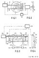
- a first device for printing plate-shaped information carriers is shown schematically in front view.
- a plate-shaped information carrier 1, which can be a compact disc, for example, is to be printed in an annular area 2.
- the plate-shaped information carrier 1 has a centrally arranged central hole 3, to which the annular region 2 is arranged concentrically.
- An area 4 is provided between the annular area 2 to be printed and the center hole 3, in which, for example, the catalog number of the information carrier or the like can be identified in a conventional manner.
- a schematically illustrated inkjet printer with a print head 19 is arranged over the annular region 2 of the plate-shaped information carrier 1.
- 5 schematically denotes a greatly enlarged pressure range.
- the print head 19 is movable along an arrow 6, which extends radially over the annular region 2.
- the print head 19 is guided over a guide rod 20 and is driven by a stepper motor 22 via a drive rod 21 (threaded spindle).
- the inkjet printer prints a radial line starting from the inner edge of the annular area 2 to the outer edge of the area, the print head 19 moving along the arrow 6 in the printing area 5.
- the plate-shaped information carrier 1 is then rotated further by a predetermined angular amount. For example, as indicated in FIG. 1 by arrow 7, this can be done clockwise.
- a radially running line is then printed again by means of the inkjet printer. This process continues in the same way until the information carrier 1 has rotated once and the annular region 2 is thus printed in a closed manner.
- a print head array can be created so that several tracks can be written at the same time and the radial path of the print head can be reduced accordingly.
- FIG. 2 shows a schematic illustration of the device according to FIG. 1 in a side view, the inkjet printer not being shown.
- the plate-shaped information carrier 1 is clamped in a receptacle 10.
- This receptacle 10 is connected to a stepper motor 12 via a shaft 11.
- the stepper motor 12 serves the plate-shaped information carrier after printing a line by means of the inkjet printer to rotate further by a defined angle.
- Both the stepper motors 12, 22 and the print head 19 of the inkjet printer are advantageously controlled in their mechanical movement by means of a suitable print program in a data processing system which also supplies the label information.
- the data processing system is indicated schematically at 23.
- Fig. 3 shows the schematic representation of another embodiment of an apparatus for use in the method for printing plate-shaped information carriers.
- the plate-shaped information carrier 31 to be printed is moved along a straight line and is not rotated in the process.
- the information carrier 1 is connected in a manner not shown in FIG. 4 to two treadmills 313, each of which runs over a deflection device 314 at its ends.
- the direction of movement resulting from the device runs from top to bottom in the plane of the drawing, as indicated by the arrow 315 in FIG. 3.
- an ink jet printer with a print head 319 is indicated above the plate-shaped information carrier 31.
- This print head 319 is along a straight line 317, which extends at a right angle to the direction of movement 315 of the plate-shaped information carrier 31, over the entire diameter of the plate-shaped information carrier 31 is movably arranged.
- With 316 the pressure area is shown schematically enlarged.
- Both the movement of the print head 319 and that of the plate-shaped information carrier 31 are advantageously controlled, similarly to the device according to FIGS. 1 and 2, by means of the same data processing system 323, which also supplies the print program for the inkjet printer.
- the information carrier 31 or 1 in FIG. 1 can be provided with other basic label information before or after the application of label information, e.g. B. is applied with a tampon or screen printing process.
- the basic information is to be regarded as fixed label information.
- the variable label information is printed on using the method according to the invention.
- FIG. 4 shows a schematic illustration of the device according to FIG. 3 in a side view, the inkjet printer not being shown.
- the plate-shaped information carrier 31 is fastened to a receptacle 318 which is connected to the two treadmills 313.
- the treadmills 13 run above and below the deflection device 314.
- the movement of the information carrier 31 by means of the treadmills 313 and the deflection device 314 can be carried out, for example, by means of a stepping motor 312 which is provided on one of the axes of the deflection devices 314.
- Printing of the plate-shaped information carrier 31 with the aid of the device shown schematically in FIGS. 3 and 4 is thus carried out in a manner similar to printing on a sheet of paper by means of a suitable printer.
- the print head 19 of the inkjet printer is moved along the straight line 17.
- the plate-shaped information carrier 31 is moved one line, for example along the straight line 315.
- the next line is printed, etc. and immediately.
- the plate-shaped information carrier if desired on the whole side, is printed with print lines running side by side and parallel to one another.
- FIG. 5 schematically shows a device for printing information carriers 51 with a laser printer 524.
- This contains a laser 525 for exposing an exposure roller 526, which is provided with an electrically chargeable layer 527 (eg selenium roller).
- the exposure roller 526 to which an ink container 528 is assigned, works together with a printing roller 529.
- 530 denotes a transport device for information carriers 51 to be printed which are transported in the direction 531.
- the data processing system 523 supplies the label information and controls the laser 525.
- z. B. CD disc there is a separate printing process. 5
- the plate 51a is already printed (see FIG. 6), the plate 51b is currently being printed, and the plate 51c is not yet printed.
- the roller 526 is exposed in accordance with the computer graphics, (label information).
- the ink from the container 528 is transferred to the printing roller 529 and from there to the pretreated CD plates 51 to be printed.
- the printed CD disk 51a is then provided with a transparent scratch protection layer.
- FIG. 6 shows a view of the exposure roller in the direction 532.
- the exposure area of the laser 525 is designated 533 and the exposed area 534.
- FIG. 7 shows a finished CD disc 51a.
- the actual information of the CD disc is located between the polycarbonate layer 535 and the metallization 536.
- 537 is a protective lacquer
- 538 the printing layer applied according to the invention and with 539 a transparent scratch protection layer, eg. B. UV paint.
Landscapes
- Engineering & Computer Science (AREA)
- General Physics & Mathematics (AREA)
- Theoretical Computer Science (AREA)
- Physics & Mathematics (AREA)
- Multimedia (AREA)
- Dot-Matrix Printers And Others (AREA)
- Ink Jet (AREA)
- Optical Record Carriers And Manufacture Thereof (AREA)
- Record Information Processing For Printing (AREA)
- Credit Cards Or The Like (AREA)
- Manufacturing Optical Record Carriers (AREA)
- Accessory Devices And Overall Control Thereof (AREA)
- Laser Beam Printer (AREA)
Abstract
Description
- Die Erfindung bezieht sich auf ein Verfahren zum Bedrucken plattenförmiger Informationsträger mit Label-Information in Form von Grafik und/oder Schrift, welche auf wenigstens einer Seite des Informationsträgers wenigstens in einem Teilbereich auf diesen aufgebracht wird.
- Auf plattenförmigen Informationsträgern ist im Regelfalle eine sogenannte Label-Information angebracht, die u. a. über den Informationsinhalt des Informationsträgers informiert. Die Label-Information enthält im allgemeinen sowohl Schrift als auch Grafik. Bei optisch auslesbaren plattenförmigen Informationsträgern, beispielsweise den sogenannten Compact-Discs, ist die Label-Information auf einer Seite des Informationsträgers in einem breiten, konzentrisch zum Mittelloch angeordneten ringförmigen Bereich vorgesehen. Diese Label-Information wird nach bekannten Verfahren in einem Siebdruck- oder in einem Tampondruckverfahren aufgebracht. Bei beiden Verfahren müssen zunächst ein Film und anschließend ein Klischee hergestellt werden, deren Anfertigung Zeit benötigt und aufwendig ist. Darüber hinaus sind die bekannten Druckverfahren unflexibel, d. h. ein schneller Wechsel verschiedener Label-Informationen zum Bedrucken verschiedener Informationsträger ist bei hohen Maschinendurchsätzen nicht möglich. Es ist praktisch nicht möglich, jeden Informationsträger individuell zu kennzeichnen.
- Es ist Aufgabe der Erfindung, ein Verfahren zum Bedrucken plattenförmiger Informationsträger der eingangs genannten Art anzugeben, welches einen flexiblen Wechsel zwischen verschiedenen Label-Informationsaufdrucken für verschiedene plattenförmige Informationsträger gestattet.
- Diese Aufgabe ist erfindungsgemäß dadurch gelöst, daß Label-Information mittels einer Datenverarbeitungsanlage erstellt wird, die Label-Information für einen Drucker aufbereitet und an diesen weiterleitet und daß der Informationsträger nach Maßgabe dieser Label-Information von dem Drucker bedruckt wird.
- Unter "Drucker" wird jede Vorrichtung verstanden, die dazu geeignet ist, den Informationsträger mit einer sichtbaren Kennzeichnung zu versehen.
- Das erfindungsgemäße Verfahren zum Bedrucken plattenförmiger Informationsträger bietet zunächst den Vorteil, daß die Label-Information oder wenigstens nicht alle Label-Information nicht mehr auf einem aufwendigen phototechnischen Wege bis hin zu einem Klischee erstellt werden muß, sondern daß es nunmehr möglich ist,Label-Information in einer Datenverarbeitungsanlage, beispielsweise unter Verwendung eines Grafikprogrammes, zu erstellen. Derartige Programme sind beispielsweise bekannt für die Lay-Out- Herstellung von Zeitungen und Zeitschriften. Diese Programme ermöglichen es, Label-Information in der gewünschten Art und Form zunächst in der Datenverarbeitungsanlage rein elektronisch zu erstellen. In diesem Stadium ist eine Änderung der Label-Information einfach möglich.
- Diese so in der Datenverarbeitungsanlage erstellte, noch rein elektronisch vorliegende Label-Information wird dann für einen Drucker aufbereitet und an diesen weitergeleitet. Die Aufbereitung der Label-Information besteht z. B. darin, daß diese in der jeweils gewünschten Struktur zeilenweise zerlegt wird, so daß ein Drucker sie entsprechend verarbeiten kann. Derartige Programme sind ebenfalls in großer Zahl bekannt für Drucker, beispielsweise Matrix- oder Tintenstrahldrucker in Datenverarbeitungsanlagen.
- Einige bekannte Druckverfahren, die angewendet werden können, sind z. B. beschrieben in der Zeitschrift Computer Design/January 1, 1988, Seiten 43 bis 49, z. B. Tintenstrahl-Druckverfahren, "solid-ink-print-Verfahren", "thermal-transfer-Verfahren", "type-diffusion-Verfahren".
- Zum weiteren Stand der Technik wird verwiesen z. B. auf die US-PSen 43 93 386, 46 04 631 und 46 80 596, in denen u. a. Druckverfahren in der Verwendung von Datenverarbeitungsanlagen beschrieben werden.
- Der Inhalt der oben genannten Druckschriften soll hiermit als in die vorliegende Beschreibung einbezogen betrachtet werden.
- Die aufbereitete und an den Drucker weitergeleitete Label-Information steuert nun den Drucker, der den Informationsträger mit der Label-Information bedruckt.
- Beim erfindungsgemäßen Verfahren ist die Erstellung von Label-Information in einer Datenverarbeitungsanlage mittels eines geeigneten Programmes schnell möglich. Auch ist eine Änderung sowohl während des Erstellungsvorganges, wie auch später rasch möglich. In der Datenverarbeitungsanlage können verschiedene Label-Informationen für plattenförmige Informationsträger mit verschiedenem Informationsinhalt erstellt werden. Es kann so regelrecht eine Datei verschiedener Label-Informationen angelegt werden, von denen die jeweils gewünschte Label-Information sehr schnell abrufbar und mittels des Druckers auf den Informationsträger aufbringbar ist. Es ist so also ein schneller Wechsel zwischen verschiedenen Label-Informationen beim Bedrucken von Informationsträgern möglich. Das Verfahren ist damit äußerst flexibel. Für die Bearbeitung der Label-Information in der Datenverarbeitungsanlage benötigte Programme, wie beispielsweise Grafikprogramme und Programme zum Aufarbeiten der Information für einen Drucker, sind in großer Zahl am Markt erhältlich und in Datenverarbeitungsanlagen meist ohnehin vorgesehen.
- Es ergibt sich außerdem der Vorteil einer kürzeren Anlaufzeit, d.h. es ist möglich, in sehr viel kürzerer Zeit als bei den Verfahren nach dem Stande der Technik eine neue Label-Information zu erstellen und plattenförmige Informationsträger einer neuen Serie damit zu bedrucken. Auch sind beispielsweise Musterandrucke in kurzer Zeit erstellbar. Damit ergibt sich durch das Bedrucken plattenförmiger Informationsträger bei Anlauf neuer Serien keine Zeitverzögerung mehr durch die Erstellung der Label-Information, bzw. der bei dem Verfahren nach dem Stande der Technik benötigten Klischees etc.
- Infolge der äußerst flexiblen Bedruckung plattenförmiger Informationsträger mit verschiedenen Label-Informationen kann sich insbesondere für kleine Stückzahlen von Informationsträgern ein Zeit- und Kostenvorteil ergeben, der das Auflegen sehr kleiner Serien mit eigenem Labelaufdruck überhaupt erst wirtschaftlich macht.
- Nach einer weitere Ausgestaltung der Erfindung ist vorgesehen, daß zum Bedrucken eines ringförmigen Bereichs des Informationsträgers ein Druckkopf radial über den ringförmigen Bereich bewegt und der Informationsträger gedreht wird.
- Wie oben bereits erwähnt, wird die in der Datenverarbeitungsanlage erstellte Label-Information mittels eines geeigneten Programmes für den Drucker aufbereitet. Derartige Programme sind bekannt und arbeiten in der Weise, daß die Information in Zeilen zerlegt wird, die dann nacheinander vom Drucker verarbeitet werden können. Sollen plattenförmige Informationsträger in einem ringförmigen Bereich mit einem Label-Aufdruck versehen werden, so ist es vorteilhaft, den Drucker bzw. dessen Druckwerk so auszulegen, daß sich der Druckkopf radial über diesen ringförmigen Bereich des Informationsträgers bewegen kann. Zusätzlich wird der plattenförmige Informationsträger gedreht. Durch eine sinnvolle Kombination dieser beiden Bewegungen ist es also möglich, den plattenförmigen Informationsträger in dem zu bedruckenden ringförmigen Bereich nacheinander zeilenweise mittels des Druckers zu bedrucken. Dazu wird beispielsweise zunächst eine radial verlaufende Zeile bedruckt, anschließend wird der Informationsträger um einen bestimmten Winkel weitergedreht, sodann wird die nächste Zeile bedruckt, und so fort. Es ergibt sich dabei vor allem der Vorteil, daß die für ein derartiges Bedrucken vorzusehende Vorrichtung in ihrem Aufbau einfach ist. Eine andere Möglichkeit besteht darin, den Informationsträger kontinuierlich zu drehen, so daß die Label-Information in konzentrischen oder spiralförmigen Spuren aufgedruckt wird. Dabei wird der Druckkopf entsprechend radial bewegt. Das Programm muß an dieses Verfahren angepaßt sein.
- Bei einer weiteren Ausgestaltung der Erfindung ist vorgesehen, daß zum Bedrucken des Informationsträgers dieser und der Druckkopf auf je einer Geraden bewegt werden, die beide in einem rechten Winkel zueinander verlaufen.
- Insbesondere in den Fällen, in denen nicht nur ein Teilbereich des Informationsträgers, sondern nahezu eine gesamte Seite bedruckt werden soll, ist ein derartiges Verfahren von Vorteil. Bei diesem Verfahren findet eine einfache zeilenweise Zerlegung von Label-Information statt, die beispielsweise der Zerlegung für einen konventionellen Papierdrucker identisch ist. Der Vorteil dieses Verfahrens besteht also darin, daß hier für Papierdrucker ohnehin vorhandene Programme zum Aufarbeiten der Information für einen Drucker auch für das Bedrucken plattenförmiger Informationsträger eingesetzt werden können.
- Nach einer weiteren Ausgestaltung der Erfindung ist als Drucker ein Tintenstrahldrucker vorgesehen. Tintenstrahldrucker eignen sich ganz besonders für das erfindungsgemäße Verfahren, weil das Verfahren kontaktlos arbeitet.
- Auch ist ein Verfahren möglich, das dadurch gekennzeichnet ist, daß für jeden Druckvorgang eine laserempfindliche Belichtungswalze entsprechend einer Computergrafik von einem Laser belichtet wird, daß die belichteten Stellen über einen Farbbehälter benetzt und auf eine Druckwalze übertragen werden und daß diese Druckinformation auf je einen über eine Transporteinrichtung herangeführten Informationsträger übertragen wird. Es sind mit diesem Verfahren qualitativ hochwertige Drucke möglich.
- Die Erfindung bezieht sich auch auf eine Vorrichtung zur Durchführung des letztgenannten Laserdruckverfahrens. Diese Vorrichtung ist gekennzeichnet durch eine von einem Laser belichtbare Belichtungswalze, der ein Farbbehälter zugeordnet ist, und durch eine mit der Belichtungswalze zusammenwirkende Druckwalze, die ihrerseits in unmittelbarer Nähe einer Transporteinrichtung für die zu bedruckenden CD-Platten angeordnet ist.
- Zum Schutz des Bedruckens ist in vielen Fällen eine Ausgestaltung des Verfahrens der Erfindung vorteilhaft, wenn der bedruckte Informationsträger mit einer transparenten Schutzschicht versehen ist.
- Nach einer weiteren Ausgestaltung der Erfindung ist für Informationsträger, die mittels des erfindungsgemäßen Verfahrens hergestellt wurden, vorgesehen, daß die Label-Information jedes einzelnen Informationsträgers eine individuelle Kennzeichnung aufweist.
- Das Verfahren bietet die wichtige Möglichkeit, plattenförmige Informationsträger einer Serie mit gleichem Informationsinhalt mit individuellen Kennungen zu versehen. Dies ist beispielsweise bei den sogenannten CD-ROM-Platten von Interesse. Eine individuelle Kennzeichnung ermöglicht die Rückverfolgung eines bestimmten Exemplars, d.h. die Kontrolle darüber, ob der Benutzer dieses Exemplars dieses rechtmäßig erworben hat. Diese Möglichkeit ist insbesondere im Zusammenhang mit dem Urheberrechtsschutz von Bedeutung. Eine solche individuelle Kennzeichnung kann auch für Musik enthaltende Informationsträger von Bedeutung sein, da sie ein Feststellen von sogenannten Raubpressungen, d. h. also von Dritten nicht rechtens erstellten Pressungen mit Platten gleichen Informationsinhalts, ermöglicht.
- In einer vorteilhaften Ausgestaltung der Erfindung können auch mehrere Verfahren zur Anwendung kommen, wobei die Label-Information mindestens eines dieser Verfahren durch eine Datenverarbeitungsanlage erstellt wird. Dabei kann z. B. die Grundinformation (Marke, Hersteller, usw.) in einem üblichen Tampon- oder Siebdruckverfahren aufgebracht werden, während die zusätzliche variable Information (Titel, Komponist, Nummern, individuelle Kennzeichnung, usw.) mit einem zusätzlichen Drucker aufgebracht wird, wobei diese Label-Information mittels einer Datenverarbeitungsanlage erstellt wird.
- Das Verfahren läßt sich ohne viel Aufwand mit den nach dem Stande der Technik bekannten Siebdruck- oder Tampondruckverfahren kombinieren. Mit diesen nach dem Stande der Technik bekannten Verfahren läßt sich z. B. auf leichte Weise ein farbiger Hintergrund erstellen, der dann mittels des Verfahrens nach der Erfindung mit weiteren, detallierten Informationen, die für verschiedene Serien verschieden sein können, bedruckt werden können.
- Anhand der Figuren werden Beispiele von Vorrichtungen zur Durchführung des erfindungsgemäßen Verfahrens näher erläutert. Es zeigen:
- Fig. 1 die schematische Darstellung der Frontansicht einer Vorrichtung zum Bedrucken plattenförmiger Informationsträger, in der diese zum Bedrucken gedreht werden,
- Fig. 2 die Vorrichtung nach Fig. 1 in Seitenansicht,
- Fig. 3 eine zweite Vorrichtung zum Bedrucken plattenförmiger Informationsträger in schematischer Darstellung und in Frontansicht,
- Fig. 4 die Vorrichtung nach Fig. 3 in Seitenansicht,
- Fig. 5 eine Vorrichtung mit einem Laserdrucker und
- Fig. 6 und 7 Einzelheiten gemäß Fig. 5.
- In Fig. 1 ist eine erste Vorrichtung zum Bedrucken plattenförmiger Informationsträger schematisch in Frontansicht dargestellt. Ein plattenförmiger Informationsträger 1, der beispielsweise eine Compact Disc sein kann, soll in einem ringförmigen Bereich 2 bedruckt werden. Der plattenförmige Informationsträger 1 weist ein zentral angeordnetes Mittelloch 3 auf, zu dem der ringförmige Bereich 2 konzentrisch angeordnet ist. Zwischen dem ringförmigen, zu bedruckenden Bereich 2 und dem Mittelloch 3 ist ein Bereich 4 vorgesehen, in dem beispielsweise eine Kennzeichnung der Katalognummer des Informationsträgers oder ähnliches in üblicher Weise vorgesehen sein kann. Über den ringförmigen Bereich 2 des plattenförmigen Informationsträgers 1 ist in diesem Ausführungsbeispiel ein schematisch dargestellter Tintenstrahldrucker mit einem Druckkopf 19 angeordnet. Mit 5 ist schematisch ein stark vergrößerter Druckbereich bezeichnet. Der Druckkopf 19 ist längs eines Pfeiles 6 beweglich, der radial über den ringförmigen Bereich 2 verläuft. Der Druckkopf 19 ist über eine Führungsstange 20 geführt und wird über eine Antriebsstange 21 (Gewindespindel) von einem Schrittmotor 22 angetrieben.
- Zum Bedrucken des ringförmigen Bereichs 2 wird nun beispielsweise zunächst eine radial in dem ringförmigen Bereich 2 verlaufende Bildzeile in der Weise gedruckt, daß der Tintenstrahldrucker beginnend am inneren Rand des ringförmigen Bereiches 2 bis zum äußeren Rand des Bereiches eine radial verlaufende Zeile druckt, wobei sich der Druckkopf 19 längs des Pfeiles 6 im Druckbereich 5 bewegt. Anschließend wird der plattenförmige Informationsträger 1 um einen festgelegten Winkelbetrag weitergedreht. Dies kann beispielsweise, wie in der Fig. 1 mittels des Pfeiles 7 angedeutet, im Uhrzeigersinn geschehen. Nach diesem Weiterdrehen des Informationsträgers 1 wird dann wiederum eine radial verlaufende Zeile mittels des Tintenstrahldruckers gedruckt. Dieser Vorgang setzt sich in gleicher Weise fort, bis der Informationsträger 1 sich einmal gedreht hat und somit der ringförmige Bereich 2 geschlossen bedruckt ist.
- Es ist alternativ möglich, die Platte 1 kontinuierlich zu drehen und die Label-Information in konzentrischen oder spiralförmigen Spuren aufzudrucken. Statt eines Druckkopfes 19 kann ein Druckkopfarray verursacht werden, so daß mehrere Spuren gleichzeitig geschrieben werden und der radiale Weg des Druckkopfes entsprechend verkleinert werden kann.
- Die Fig. 2 zeigt in schematischer Darstellung die Vorrichtung nach Fig. 1 in Seitenansicht, wobei der Tintenstrahldrucker nicht dargestellt ist. Der plattenförmige Informationsträger 1 ist in einer Aufnahme 10 festgeklemmt. Diese Aufnahme 10 ist über eine Welle 11 mit einem Schrittmotor 12 verbunden. Der Schrittmotor 12 dient dazu, den plattenförmigen Informationsträger nach Bedrucken einer Zeile mittels des Tintenstrahldruckers um einen definierten Winkel weiterzudrehen. In vorteilhafter Weise werden sowohl die Schrittmotoren 12, 22, wie auch der Druckkopf 19 des Tintenstrahldruckers in ihrer mechanischen Bewegung mittels eines geeigneten Druckprogramms in einer Datenverarbeitungsanlage, die auch die Label-Information liefert, gesteuert. Die Datenverarbeitungsanlage ist schematisch mit 23 angedeutet.
- Fig. 3 zeigt die schematische Darstellung einer anderen Ausführungsform einer Vorrichtung zum Einsatz für das Verfahren zum Bedrucken plattenförmiger Informationsträger. Bei dieser in Fig. 3 dargestellten Vorrichtung wird der zu bedruckende plattenförmige Informationsträger 31 entlang einer Geraden bewegt und dabei nicht gedreht. Der Informationsträger 1 ist dazu in in der Fig. 4 nicht näher dargestellter Weise mit zwei Laufbändern 313 verbunden, die an ihren Enden über je eine Umlenkvorrichtung 314 laufen. Die sich mittels der Vorrichtung ergebende Bewegungsrichtung verläuft in der Zeichenebene von oben nach unten, wie dies in der Fig. 3 mittels des Pfeiles 315 angedeutet ist.
- Oberhalb des plattenförmigen Informationsträgers 31 ist in diesem Ausführungsbeispiel ein Tintenstrahldrucker mit einem Druckkopf 319 (oder Druckkopfarray) angedeutet. Dieser Druckkopf 319 ist längs einer Geraden 317, welche in einem rechten Winkel zu der Bewegungsrichtung 315 des plattenförmigen Informationsträgers 31 verläuft, über den gesamten Durchmesser des plattenförmigen Informationsträgers 31 beweglich angeordnet. Mit 316 ist schematisch der stark vergrößert dargestellte Druckbereich dargestellt.
- Sowohl die Bewegung des Druckkopfes 319 als auch die des plattenförmigen Informationsträgers 31 werden vorteilhafterweise, ähnlich wie bei der Vorrichtung nach den Fig. 1 und 2, mittels der gleichen Datenverarbeitungsanlage 323 angesteuert, die auch das Druckprogramm für den Tintenstrahldrucker liefert. Der Informationsträger 31 oder 1 in Fig. 1 kann vor oder nach Aufbringen einer Label-Information mit einer anderen Grund-Label-Information versehen sein, die z. B. mit einem Tampon- oder Siebdruckverfahren aufgebracht wird. Die Grundinformation ist als feste Label-Information zu betrachten. Die variable Label-Information wird mittels des erfindungsgemäßen Verfahrens aufgedruckt.
- In Fig. 4 ist eine schematische Darstellung der Vorrichtung nach Fig. 3 in Seitenansicht dargestellt, wobei der Tintenstrahldrucker nicht dargestellt ist. Der plattenförmige Informationsträger 31 ist an einer Aufnahme 318 befestigt, welche mit den beiden Laufbändern 313 verbunden ist. Die Laufbänder 13 laufen oben und unten über die Umlenkvorrichtung 314. Die Bewegung des Informationsträgers 31 mittels der Laufbänder 313 und der Umlenkvorrichtung 314 kann beispielsweise mittels eines Schrittmotors 312 vorgenommen werden, der auf einer der Achsen der Umlenkvorrichtungen 314 vorgesehen ist.
- Eine Bedruckung des plattenförmigen Informationsträgers 31 mit Hilfe der in den Fig. 3 und 4 schematisch dargestellten Vorrichtung wird also in ähnlicher Weise wie das Bedrucken eines Blattes Papier mittels eines geeigneten Druckers vorgenommen. Für das Drucken einer Zeile wird der Druckkopf 19 des Tintenstrahldruckers längs der Geraden 17 bewegt. Nach Bedrucken dieser Zeile wird der plattenförmige Informationsträger 31 eine Zeile, beispielsweise längs der Geraden 315 weiterbewegt. Anschließend wird die nächste Zeile gedruckt, usw. und sofort. Auf diese Weise wird der plattenförmige Informationsträger, gewünschtenfalls ganzseitig, mit nebeneinander und parallel zueinander verlaufenden Druckzeilen bedruckt.
- Fig. 5 zeigt schematisch eine Vorrichtung zum Bedrucken von Informationsträgern 51 mit einem Laserdrucker 524. Dieser enthält einen Laser 525 zum Belichten einer Belichtungswalze 526, die mit einer elektrisch aufladbaren Schicht 527 versehen ist (z. B. Selenwalze). Die Belichtungswalze 526, der ein Farbbehälter 528 zugeordnet ist, arbeitet zusammen mit einer Druckwalze 529. Mit 530 ist eine Transporteinrichtung für in Richtung 531 transportierte, zu bedruckende Informationsträger 51 bezeichnet. Die Datenverarbeitungsanlage 523 liefert die Label-Information und steuert den Laser 525 an. Für jeden einzelnen zu bedruckenden Informationsträger 51, z. B. CD-Platte, erfolgt ein gesonderter Druckvorgang. Gemäß Fig. 5 ist die Platte 51a fertig bedruckt (siehe Fig. 6), die Platte 51b wird gerade bedruckt, und die Platte 51c ist noch nicht bedruckt.
- Die Walze 526 wird entsprechend der Computergrafik, (Label-Information) belichtet. Die Farbe aus dem Behälter 528 wird auf die Druckwalze 529 und von hier auf die vorbehandelten, zu bedruckenden CD-Platten 51 übertragen. Die bedruckte CD-Platte 51a wird anschließend mit einer transparenten Kratzschutzschicht versehen.
- Fig. 6 zeigt eine Ansicht der Belichtungswalze in Richtung 532. Dabei ist der Belichtungsbereich des Lasers 525 mit 533 und der belichtete Bereich mit 534 bezeichnet.
- Fig. 7 zeigt eine fertige CD-Platte 51a. Die eigentliche Information der CD-Platte befindet sich zwischen der Polykarbonatschicht 535 und der Metallisierung 536. Mit 537 ist ein Schutzlack, mit 538 die gemäß der Erfindung aufgebrachte Druckschicht und mit 539 eine transparente Kratzschutzschicht, z. B. UV-Lack, bezeichnet.
- Die Verwendung eines Laserdruckers erfordert wenig Aufwand und liefert qualitativ hochwertige Drucke.
Claims (9)
Applications Claiming Priority (2)
| Application Number | Priority Date | Filing Date | Title |
|---|---|---|---|
| DE19873721651 DE3721651A1 (de) | 1987-07-01 | 1987-07-01 | Verfahren zum bedrucken plattenfoermiger informationstraeger |
| DE3721651 | 1987-07-01 |
Publications (3)
| Publication Number | Publication Date |
|---|---|
| EP0297668A2 true EP0297668A2 (de) | 1989-01-04 |
| EP0297668A3 EP0297668A3 (de) | 1991-03-20 |
| EP0297668B1 EP0297668B1 (de) | 1994-09-28 |
Family
ID=6330620
Family Applications (1)
| Application Number | Title | Priority Date | Filing Date |
|---|---|---|---|
| EP88201322A Expired - Lifetime EP0297668B1 (de) | 1987-07-01 | 1988-06-27 | Verfahren zum Bedrucken plattenförmiger Informationsträger |
Country Status (8)
| Country | Link |
|---|---|
| US (1) | US5317337A (de) |
| EP (1) | EP0297668B1 (de) |
| JP (2) | JP2794628B2 (de) |
| KR (1) | KR960001643B1 (de) |
| AT (1) | ATE112404T1 (de) |
| DE (2) | DE3721651A1 (de) |
| ES (1) | ES2066780T3 (de) |
| HK (1) | HK65996A (de) |
Cited By (17)
| Publication number | Priority date | Publication date | Assignee | Title |
|---|---|---|---|---|
| EP0574860A3 (de) * | 1992-06-13 | 1994-01-12 | Taiyo Yuden Kk | |
| EP0591041A3 (de) * | 1992-09-28 | 1994-11-23 | Sony Corp | Selbstklebendes Informationsetikett für Aufzeichnungsträgerkassette und Etikettienverfahren damit. |
| EP0628956A1 (de) * | 1993-04-10 | 1994-12-14 | Taiyo Yuden Co., Ltd. | Optisches Informationsaufzeichnungsmedium und Verfahren zu dessen Herstellung |
| WO1997001800A1 (en) * | 1995-06-29 | 1997-01-16 | Eastman Kodak Company | Apparatus and method for digital disc labelling and packaging |
| WO1997001843A1 (en) * | 1995-06-29 | 1997-01-16 | Eastman Kodak Company | Method and apparatus for preparing, on demand, a selected information package, including digital and print media, from a catalog of information packages |
| WO1997001844A1 (en) * | 1995-06-29 | 1997-01-16 | Eastman Kodak Company | Method and apparatus for writing and labelling individual digital discs |
| WO1997001845A1 (en) * | 1995-06-29 | 1997-01-16 | Eastman Kodak Company | Method and apparatus for preparing labelled digital disc |
| EP0754123A4 (de) * | 1995-02-03 | 1997-06-11 | Rimage Corp | Vorrichtung zum drucken auf einer kunststoffscheibe |
| EP0762420A3 (de) * | 1995-08-31 | 1997-07-16 | Eastman Kodak Co | Klemmgerät zum Eindrucken von scheibenförmigen Informationsmedien |
| EP0768666A3 (de) * | 1995-10-12 | 1997-07-16 | Eastman Kodak Co | Klemmvorrichtung zum Bedrucken von plattenförmigen Informationsträgern |
| US5907345A (en) * | 1996-06-18 | 1999-05-25 | Eastman Kodak Company | Apparatus and method for digital disc labelling and packaging |
| WO1999052713A1 (en) * | 1998-04-15 | 1999-10-21 | Stephen David Woods | Inkjet printer for printing compact disks |
| WO1999064242A3 (en) * | 1998-06-08 | 2000-03-16 | Primera Technology Inc | Compact disc and recordable compact disc thermal transfer printer |
| US6109324A (en) * | 1996-06-17 | 2000-08-29 | Eastman Kodak Company | Method and apparatus for preparing labelled digital disc |
| US6302601B1 (en) | 1998-06-08 | 2001-10-16 | Primera Technology, Inc. | Substrate carrier and printhead mounting for printer |
| US6447181B1 (en) | 1998-06-08 | 2002-09-10 | Primera Technology, Inc. | Variable position, force and velocity printer |
| EP1501087A3 (de) * | 2003-07-24 | 2006-04-26 | Hewlett-Packard Development Company, L.P. | Schreiben von Pixeln in letzte Pixelbruchteilsstellen in Spuren auf optischen Platten |
Families Citing this family (118)
| Publication number | Priority date | Publication date | Assignee | Title |
|---|---|---|---|---|
| JP2515557B2 (ja) * | 1987-08-12 | 1996-07-10 | キヤノン株式会社 | 光記録媒体およびその製造方法 |
| DE3901806A1 (de) * | 1989-01-23 | 1990-07-26 | Pavel Wilfried Maschinen | Verfahren zum anbringen eines maschinenlesbaren identifikationscodes an kleiderbuegel und kleiderbuegel mit maschinenlesbarem identifikationscode |
| US5518325A (en) * | 1994-02-28 | 1996-05-21 | Compulog | Disk label printing |
| US6264321B1 (en) | 1994-05-31 | 2001-07-24 | Eastman Kodak Company | Method of producing recorded images having enhanced durability on a variety of substrates |
| US5592596A (en) * | 1995-06-08 | 1997-01-07 | Sony Corporation | System and method for the automatic printing of storage media labels |
| JPH10505454A (ja) * | 1995-06-29 | 1998-05-26 | イーストマン コダック カンパニー | デジタルディスクに転写可能な画像を融着する方法および積層ジャケット |
| JPH10505438A (ja) * | 1995-06-29 | 1998-05-26 | イーストマン コダック カンパニー | 転写支持体及びデジタルディスクへの転写性画像の融合方法 |
| JP3126302B2 (ja) * | 1995-09-29 | 2001-01-22 | 株式会社マスターマインド | 板状記録媒体の印刷装置 |
| DE19604204A1 (de) | 1996-02-06 | 1997-08-07 | Kodak Ag | Transportvorrichtung zum linearen Bewegen eines Transporttisches |
| US6019151A (en) * | 1997-01-07 | 2000-02-01 | Eastman Kodak Company | Printing onto discs such as compact discs and the like |
| GB2320912B (en) * | 1997-01-07 | 2001-12-05 | Eastman Kodak Co | Apparatus and process for digital printing images in annular-radial coordinate s onto discs |
| US5894069A (en) * | 1997-02-12 | 1999-04-13 | Eastman Kodak Company | Transferring colorant from a donor element to a compact disc |
| US5781221A (en) * | 1997-02-28 | 1998-07-14 | Eastman Kodak Company | Method of printing visually readable information on a compact disk |
| US5915858A (en) * | 1997-03-07 | 1999-06-29 | Eastman Kodak Company | Organizing pixels of different density levels for printing human readable information on CDs |
| US5854175A (en) * | 1997-04-09 | 1998-12-29 | Eastman Kodak Company | Embossed compact disc surfaces for laser thermal labeling |
| US6222800B1 (en) | 1997-06-02 | 2001-04-24 | Copy Pro, Inc. | Autoload disk copier system |
| EP0895242A1 (de) | 1997-07-28 | 1999-02-03 | THOMSON multimedia | Verfahren zur Benutzeranpassung eiens Datenspeichermediums |
| US6074031A (en) * | 1997-12-11 | 2000-06-13 | Compulog Corporation | Method and apparatus for printing labels on digital recording media |
| US6270176B1 (en) * | 1997-12-11 | 2001-08-07 | Compulog Corporation | Method and apparatus for printing labels on digital recording media |
| US5967676A (en) * | 1998-03-31 | 1999-10-19 | Microtech Conversion Systems, Inc. | Image orientation system for disk printing |
| US7850276B2 (en) * | 1998-04-17 | 2010-12-14 | Elesys, Inc. | Radial sled printing apparatus and methods |
| US7085017B1 (en) * | 2001-08-03 | 2006-08-01 | Elesys, Inc. | Polar halftone methods for radial printing |
| US6986559B1 (en) | 2001-04-20 | 2006-01-17 | Elesys, Inc. | Position information apparatus and methods for radial printing |
| US7748807B2 (en) * | 1998-04-17 | 2010-07-06 | Elesys, Inc. | Off-radial-axis circular printing device and methods |
| US6264295B1 (en) | 1998-04-17 | 2001-07-24 | Elesys, Inc. | Radial printing system and methods |
| US6786563B1 (en) * | 2001-04-18 | 2004-09-07 | Elesys, Inc. | Interleaving apparatus and methods for radial printing |
| US6910750B2 (en) | 2000-06-02 | 2005-06-28 | Elesys, Inc. | Low-profile ink head cartridge with integrated movement mechanism and service station |
| US7284804B2 (en) * | 2001-04-18 | 2007-10-23 | Elesys, Inc. | Interleaving apparatus and methods for radial printing |
| US7497534B2 (en) * | 2000-03-21 | 2009-03-03 | Elesys, Inc. | Enhancing angular position information for a radial printing system |
| US6854841B1 (en) | 1998-04-17 | 2005-02-15 | Elesys, Inc. | Point-of-incidence ink-curing mechanisms for radial printing |
| US6386667B1 (en) * | 1998-04-24 | 2002-05-14 | Hewlett-Packard Company | Technique for media coverage using ink jet writing technology |
| US6310691B2 (en) * | 1998-04-24 | 2001-10-30 | Hewlett-Packard Company | Technique for scanning documents using a spiral path locus |
| JPH11334046A (ja) * | 1998-04-24 | 1999-12-07 | Hewlett Packard Co <Hp> | インクジェットノズルアレイによる媒体の領域に対する印刷方法 |
| US6337842B1 (en) | 1998-06-01 | 2002-01-08 | Microboards Technology, L.L.C. | Disk handling system having a telescoping elevator pin |
| US7032232B2 (en) * | 1998-06-01 | 2006-04-18 | Microboards Technology, Llc | Memory storage disk handling system |
| US6384929B1 (en) | 1998-06-17 | 2002-05-07 | Wordtech, Inc. | Self-orienting printer controller for printing on the non-recordable label face of a compact disk |
| WO2000002732A1 (en) * | 1998-07-09 | 2000-01-20 | Primera Technology, Inc. | Variable velocity compact disc printer |
| JP2000113511A (ja) * | 1998-09-30 | 2000-04-21 | Fuji Photo Film Co Ltd | 光情報記録媒体 |
| US20020114627A1 (en) * | 1998-10-21 | 2002-08-22 | Truc James A. | CD index print label |
| US6312174B1 (en) * | 1998-11-13 | 2001-11-06 | Wordtech Systems, Inc. | Thermal printer for compact disks |
| IL127317A0 (en) * | 1998-11-29 | 1999-09-22 | Ink Jet Technology | Printing mechanism for digital discs |
| US6202550B1 (en) * | 1998-12-30 | 2001-03-20 | Eastman Kodak Company | Printer and method for printing indicia on a compact disk using a plurality of ink jet or laser rotatable print heads |
| JP2000339772A (ja) * | 1999-05-28 | 2000-12-08 | Olympus Optical Co Ltd | 光ディスク、および光ディスクのラベル層形成装置 |
| EP1081695A3 (de) * | 1999-08-27 | 2001-05-02 | Star Micronics Co., Ltd. | Plattenladegerät, Verfahren und Vorrichtung zum Montieren einer Platte auf einem rotierenden Plattenmechanismus, und rotierendes Druckgerät |
| DE19941673A1 (de) | 1999-09-01 | 2001-03-15 | Pelikan Produktions Ag Egg | Verfahren zum Bedrucken von nicht-porösen Oberflächen |
| US7302164B2 (en) | 2000-02-11 | 2007-11-27 | Datcard Systems, Inc. | System and method for producing medical image data onto portable digital recording media |
| US6556803B2 (en) * | 2000-07-28 | 2003-04-29 | Tohoku Ricoh Co., Ltd. | Image forming apparatus for synthetic resin sheets |
| JP2002103582A (ja) * | 2000-09-27 | 2002-04-09 | Seiko Epson Corp | データ記録媒体の表面層への印刷 |
| US7268794B2 (en) * | 2000-10-30 | 2007-09-11 | Yamaha Corporation | Method of printing label on optical disk, optical disk unit, and optical disk |
| US20020101497A1 (en) * | 2001-01-30 | 2002-08-01 | Kwasny David M. | Method for creating durable printed CD's using clear hot stamp coating |
| JP2004528209A (ja) * | 2001-06-01 | 2004-09-16 | エレシス・インコーポレーテッド | 統合された運動機構およびサービスステーションを持つロープロファイルインクヘッドカートリッジ |
| GB2376920A (en) * | 2001-06-27 | 2002-12-31 | Inca Digital Printers Ltd | Inkjet printing on a three-dimensional object including relative movement of a printhead and the object during printing about a rotational axis |
| US7172991B2 (en) * | 2001-10-11 | 2007-02-06 | Hewlett-Packard Development Company, L.P. | Integrated CD/DVD recording and labeling |
| JP3956756B2 (ja) * | 2001-10-31 | 2007-08-08 | ヤマハ株式会社 | 光ディスク記録装置 |
| US6771297B2 (en) | 2002-01-11 | 2004-08-03 | Hewlett-Packard Development Company, L.P. | Labeling apparatus and method for disk storage media |
| US6903760B2 (en) * | 2002-01-30 | 2005-06-07 | Hewlett-Packard Development Company, L.P. | Method and system for labeling a storage media |
| US6778205B2 (en) | 2002-02-28 | 2004-08-17 | Hewlett-Packard Development Company, L.P. | Methods and apparatuses for forming visible labels on objects using a writable optical disc drive |
| JP3873784B2 (ja) * | 2002-03-13 | 2007-01-24 | ヤマハ株式会社 | 光ディスク装置 |
| US6793302B2 (en) | 2002-03-22 | 2004-09-21 | Microboards Technology, Llc | In-line marking system |
| TWI235713B (en) * | 2002-04-26 | 2005-07-11 | Casio Computer Co Ltd | Printing apparatus, printing method and computer-readable recording medium |
| JP4096609B2 (ja) * | 2002-04-26 | 2008-06-04 | カシオ計算機株式会社 | 印刷装置 |
| TWI238784B (en) * | 2002-04-26 | 2005-09-01 | Casio Computer Co Ltd | Printing apparatus, printing method and computer readable recording media |
| US6580444B1 (en) | 2002-04-30 | 2003-06-17 | Alexander V. Drynkin | Thermal printer for compact disks and other media |
| JP4062976B2 (ja) * | 2002-05-31 | 2008-03-19 | ヤマハ株式会社 | 光ディスクへの画像形成装置および画像形成方法 |
| US6867793B2 (en) | 2002-05-31 | 2005-03-15 | Hewlett-Packard Development Company, L.P. | Method and materials for entitling compact discs |
| JP3858149B2 (ja) * | 2002-06-28 | 2006-12-13 | カシオ計算機株式会社 | 印刷装置及び印刷方法 |
| JP3758614B2 (ja) | 2002-06-28 | 2006-03-22 | ヤマハ株式会社 | 光ディスク記録装置及び光ディスクに対する画像形成方法 |
| JP3780232B2 (ja) * | 2002-07-10 | 2006-05-31 | キヤノン株式会社 | 記録装置 |
| JP3900270B2 (ja) * | 2002-07-25 | 2007-04-04 | セイコーエプソン株式会社 | 印刷装置、ディスク中心点検出制御プログラム |
| JP4088771B2 (ja) * | 2002-10-03 | 2008-05-21 | セイコーエプソン株式会社 | 記録装置 |
| US7390362B2 (en) * | 2002-10-15 | 2008-06-24 | Microboards Llc | Thermal printer |
| US7150790B2 (en) * | 2002-10-15 | 2006-12-19 | Microboards Technology, Llc | In-line marking system |
| US7063746B2 (en) * | 2002-10-15 | 2006-06-20 | Microbroads Technology, Llc | In-line marking system |
| US6887313B2 (en) * | 2002-10-15 | 2005-05-03 | Microboards Technology, Llc | In-line marking system |
| US7084895B2 (en) * | 2002-12-12 | 2006-08-01 | Hewlett-Packard Development Company, L.P. | Multiple passes over tracks of and radially non-collinear track starting positions on label side of optical disc |
| US7307649B2 (en) * | 2002-12-12 | 2007-12-11 | Hewlett-Packard Development Company, L.P. | Optical disc non-cartesian coordinate system |
| JP2004209813A (ja) * | 2002-12-27 | 2004-07-29 | Casio Comput Co Ltd | 印刷装置 |
| JP4417012B2 (ja) * | 2003-01-08 | 2010-02-17 | 三菱化学メディア株式会社 | 光情報記録媒体 |
| WO2004110578A1 (en) * | 2003-06-09 | 2004-12-23 | Serigraph Inc. | Digital data trading or gift card |
| US20040263561A1 (en) * | 2003-06-27 | 2004-12-30 | Kurt Thiessen | System and method of printing within circular area |
| US7483184B2 (en) * | 2003-10-09 | 2009-01-27 | Hewlett-Packard Development Company, L.P. | Method and system for using an optical sensor array to control a labeling device |
| EP1750949A2 (de) * | 2004-04-28 | 2007-02-14 | Elesys, Inc. | Radial-sled-druckvorrichtung und verfahren |
| US7639271B2 (en) * | 2004-04-30 | 2009-12-29 | Hewlett-Packard Development Company, L.P. | Labeling an optical disc |
| GB0412969D0 (en) * | 2004-06-10 | 2004-07-14 | Esselte | Thermal laser printing |
| US7907160B2 (en) * | 2004-07-23 | 2011-03-15 | Hewlett-Packard Development Company, L.P. | Track labeling on a medium |
| US20060132576A1 (en) * | 2004-12-22 | 2006-06-22 | Lowery David C | Optical media with laminated inkjet receptor |
| US7540237B2 (en) * | 2005-01-19 | 2009-06-02 | Kubin Dale K | Printer |
| JP2006210512A (ja) * | 2005-01-26 | 2006-08-10 | Toshiba Corp | 半導体装置、及び、半導体装置の製造方法 |
| WO2006089295A2 (en) * | 2005-02-18 | 2006-08-24 | Elesys, Inc. | Off-radial-axis circular printing device and methods |
| US7484820B2 (en) * | 2005-03-30 | 2009-02-03 | Brother Kogyo Kabushiki Kaisha | Recording apparatus for rotating recording medium |
| US20060248551A1 (en) * | 2005-04-28 | 2006-11-02 | Taugher Lawrence N | Single motor connected to an optical pick up unit and an optical print head |
| US20070025794A1 (en) * | 2005-06-17 | 2007-02-01 | Kubin Dale K | A printer |
| US20070024694A1 (en) * | 2005-07-27 | 2007-02-01 | Hanks Darwin M | Thermal print head |
| US20070070169A1 (en) * | 2005-09-28 | 2007-03-29 | Hanks D M | Laser positioning in an optical disc drive |
| KR100688599B1 (ko) * | 2005-11-03 | 2007-03-02 | 도시바삼성스토리지테크놀러지코리아 주식회사 | 광디스크용 라벨 프린터를 구비한 광기록/재생 장치 및광디스크에 라벨을 인쇄하는 방법 |
| US7933472B1 (en) | 2006-04-26 | 2011-04-26 | Datcard Systems, Inc. | System for remotely generating and distributing DICOM-compliant media volumes |
| US7538788B2 (en) * | 2006-05-01 | 2009-05-26 | Hewlett-Packard Development Company, L.P. | Label writing |
| US20080062244A1 (en) * | 2006-09-11 | 2008-03-13 | Hewlett-Packard Development Company Lp | Laser writing |
| US7700175B2 (en) * | 2006-09-11 | 2010-04-20 | Hewlett-Packard Development Company, L.P. | Storage disc |
| US20080063900A1 (en) * | 2006-09-11 | 2008-03-13 | Hewlett-Packard Development Company Lp | Optical storage medium |
| US20080092153A1 (en) * | 2006-10-11 | 2008-04-17 | Imation Corp. | System and process for forming a durable image on an optical disk |
| US7946668B2 (en) | 2006-10-13 | 2011-05-24 | Fujifilm Dimatix, Inc. | Printing on a rotating surface |
| JP5009639B2 (ja) * | 2007-02-09 | 2012-08-22 | 株式会社リコー | レーザ書換システム |
| US20080256565A1 (en) * | 2007-03-16 | 2008-10-16 | Xlnt Idea, Inc. | Disc transport and method of disc removal |
| US20080229342A1 (en) * | 2007-03-16 | 2008-09-18 | Kubin Dale K | Method for picking and placing a disc |
| US20080229341A1 (en) * | 2007-03-16 | 2008-09-18 | Kubin Dale K | Disc transport with an improved disc engagement mechanism |
| US20080244627A1 (en) * | 2007-03-26 | 2008-10-02 | Kubin Dale K | Disc transport with carousel |
| US20080267018A1 (en) * | 2007-04-03 | 2008-10-30 | Xlnt Idea, Inc. | Disc transport auto-calibration |
| US20080271064A1 (en) * | 2007-04-26 | 2008-10-30 | Kubin Dale K | Portable integrated disc-publishing device |
| JP4881243B2 (ja) * | 2007-07-09 | 2012-02-22 | アルプス電気株式会社 | ディスクレーベルプリンタ |
| JP4970387B2 (ja) * | 2008-08-21 | 2012-07-04 | アルプス電気株式会社 | 記録装置 |
| US7843479B2 (en) * | 2008-10-16 | 2010-11-30 | Coherent, Inc. | Method for providing a plurality of laser-printed labels from a medium supported on a disc |
| US8354611B2 (en) * | 2008-10-29 | 2013-01-15 | Coherent, Inc. | Laser engraving apparatus |
| JP2012108974A (ja) * | 2010-11-16 | 2012-06-07 | Sony Corp | ディスク駆動装置 |
| US8823757B2 (en) * | 2012-02-28 | 2014-09-02 | Ncr Corporation | Thermal transfer ribbon for finishing a printed label and method of manufacturing a thermal transfer ribbon therfor |
| CN105015176A (zh) * | 2015-07-03 | 2015-11-04 | 宁波科镭仕激光科技有限公司 | 一种新型旋转打标机 |
| JP6787000B2 (ja) * | 2016-09-27 | 2020-11-18 | カシオ計算機株式会社 | 印刷装置 |
| CN106739537A (zh) * | 2017-02-23 | 2017-05-31 | 重庆亮科激光科技有限公司 | 一种用于抽油杆接箍的内孔激光打标设备及其打标方法 |
Family Cites Families (15)
| Publication number | Priority date | Publication date | Assignee | Title |
|---|---|---|---|---|
| US4068028A (en) * | 1971-06-09 | 1978-01-10 | Unical Corporation | Apparatus and method of producing transparent labels with printing on the adhesive and product produced thereby |
| US4066268A (en) * | 1972-04-21 | 1978-01-03 | Ted Bildplatten Aktiengesellschaft Aeg-Telefunken-Teldec | Disc recording provided with legible matter |
| DE2304723A1 (de) * | 1973-01-31 | 1974-08-08 | Polygram Gmbh | Scheibenfoermiger informationstraeger, sowie verfahren und einrichtung zu dessen herstellung |
| DE2535699C3 (de) * | 1975-08-09 | 1978-12-14 | Olympia Werke Ag, 2940 Wilhelmshaven | Verfahren und Drucker zur Herstellung von feingerasterten Schriftzeichen auf einem Aufzeichnungsträger |
| JPS5227562A (en) * | 1975-08-28 | 1977-03-01 | Tokyo Shibaura Electric Co | Gas breaker |
| JPS5352442A (en) * | 1976-10-23 | 1978-05-12 | Fujitsu Ltd | Laser recorder |
| JPS5513069A (en) * | 1978-07-14 | 1980-01-29 | Kubota Ltd | Soil treatinggwork machine |
| GB2077970B (en) * | 1980-02-26 | 1984-12-19 | Teraoka Seikosho Kk | A label printer |
| JPS5773136U (de) * | 1980-10-24 | 1982-05-06 | ||
| US4393386A (en) * | 1981-09-30 | 1983-07-12 | Pitney Bowes Inc. | Ink jet printing apparatus |
| GB2120821B (en) * | 1982-05-18 | 1985-08-29 | Weyfringe Limited | Label printer |
| CA1210316A (en) * | 1982-09-02 | 1986-08-26 | Robin Louvel | Marking apparatus |
| JPS60122162A (ja) * | 1983-12-07 | 1985-06-29 | Ricoh Co Ltd | 荷電制御型インクジエツトプリンタ− |
| US4680596A (en) * | 1984-08-02 | 1987-07-14 | Metromedia Company | Method and apparatus for controlling ink-jet color printing heads |
| FR2907177B1 (fr) | 2006-10-13 | 2009-12-04 | Snecma | Assemblage d'un dispositif rotulant sur une chape de renvoi d'angle, systeme de commande d'un redresseur a calage variable le comportant, et moteur d'aeronef en etant muni |
-
1987
- 1987-07-01 DE DE19873721651 patent/DE3721651A1/de not_active Withdrawn
-
1988
- 1988-06-27 DE DE3851661T patent/DE3851661D1/de not_active Expired - Lifetime
- 1988-06-27 ES ES88201322T patent/ES2066780T3/es not_active Expired - Lifetime
- 1988-06-27 EP EP88201322A patent/EP0297668B1/de not_active Expired - Lifetime
- 1988-06-27 AT AT88201322T patent/ATE112404T1/de not_active IP Right Cessation
- 1988-07-01 JP JP63162780A patent/JP2794628B2/ja not_active Expired - Lifetime
- 1988-07-01 KR KR1019880008174A patent/KR960001643B1/ko not_active Expired - Lifetime
-
1990
- 1990-03-22 US US07/497,831 patent/US5317337A/en not_active Expired - Lifetime
-
1996
- 1996-04-18 HK HK6500696A patent/HK65996A/xx not_active IP Right Cessation
-
1998
- 1998-02-05 JP JP02458898A patent/JP3452475B2/ja not_active Expired - Lifetime
Cited By (22)
| Publication number | Priority date | Publication date | Assignee | Title |
|---|---|---|---|---|
| EP0574860A3 (de) * | 1992-06-13 | 1994-01-12 | Taiyo Yuden Kk | |
| EP0591041A3 (de) * | 1992-09-28 | 1994-11-23 | Sony Corp | Selbstklebendes Informationsetikett für Aufzeichnungsträgerkassette und Etikettienverfahren damit. |
| US5436059A (en) * | 1992-09-28 | 1995-07-25 | Sony Corporation | Self-adhesive informative label for a recording medium-accommodating cassettes and labelling method using the same |
| EP0628956A1 (de) * | 1993-04-10 | 1994-12-14 | Taiyo Yuden Co., Ltd. | Optisches Informationsaufzeichnungsmedium und Verfahren zu dessen Herstellung |
| US5470691A (en) * | 1993-04-10 | 1995-11-28 | Taiyo Yuden, Co., Ltd. | Optical information medium |
| EP0754123A4 (de) * | 1995-02-03 | 1997-06-11 | Rimage Corp | Vorrichtung zum drucken auf einer kunststoffscheibe |
| WO1997001800A1 (en) * | 1995-06-29 | 1997-01-16 | Eastman Kodak Company | Apparatus and method for digital disc labelling and packaging |
| WO1997001843A1 (en) * | 1995-06-29 | 1997-01-16 | Eastman Kodak Company | Method and apparatus for preparing, on demand, a selected information package, including digital and print media, from a catalog of information packages |
| WO1997001844A1 (en) * | 1995-06-29 | 1997-01-16 | Eastman Kodak Company | Method and apparatus for writing and labelling individual digital discs |
| WO1997001845A1 (en) * | 1995-06-29 | 1997-01-16 | Eastman Kodak Company | Method and apparatus for preparing labelled digital disc |
| EP0762420A3 (de) * | 1995-08-31 | 1997-07-16 | Eastman Kodak Co | Klemmgerät zum Eindrucken von scheibenförmigen Informationsmedien |
| EP0768666A3 (de) * | 1995-10-12 | 1997-07-16 | Eastman Kodak Co | Klemmvorrichtung zum Bedrucken von plattenförmigen Informationsträgern |
| US6109324A (en) * | 1996-06-17 | 2000-08-29 | Eastman Kodak Company | Method and apparatus for preparing labelled digital disc |
| US5907345A (en) * | 1996-06-18 | 1999-05-25 | Eastman Kodak Company | Apparatus and method for digital disc labelling and packaging |
| WO1999052713A1 (en) * | 1998-04-15 | 1999-10-21 | Stephen David Woods | Inkjet printer for printing compact disks |
| GB2353975A (en) * | 1998-04-15 | 2001-03-14 | Stephen David Woods | Inkjet printer for printing compact disks |
| WO1999064242A3 (en) * | 1998-06-08 | 2000-03-16 | Primera Technology Inc | Compact disc and recordable compact disc thermal transfer printer |
| US6148722A (en) * | 1998-06-08 | 2000-11-21 | Primera Technology, Inc. | Compact disc and recordable compact disc thermal transfer printer |
| US6302601B1 (en) | 1998-06-08 | 2001-10-16 | Primera Technology, Inc. | Substrate carrier and printhead mounting for printer |
| US6447181B1 (en) | 1998-06-08 | 2002-09-10 | Primera Technology, Inc. | Variable position, force and velocity printer |
| EP1501087A3 (de) * | 2003-07-24 | 2006-04-26 | Hewlett-Packard Development Company, L.P. | Schreiben von Pixeln in letzte Pixelbruchteilsstellen in Spuren auf optischen Platten |
| US7139232B2 (en) | 2003-07-24 | 2006-11-21 | Hewlett-Packard Development Company, L.P. | Writing pixels to last fractional pixel positions of tracks of optical discs |
Also Published As
| Publication number | Publication date |
|---|---|
| KR890002795A (ko) | 1989-04-11 |
| HK65996A (en) | 1996-04-26 |
| DE3721651A1 (de) | 1989-01-12 |
| DE3851661D1 (de) | 1994-11-03 |
| US5317337A (en) | 1994-05-31 |
| JPH115332A (ja) | 1999-01-12 |
| JP3452475B2 (ja) | 2003-09-29 |
| ES2066780T3 (es) | 1995-03-16 |
| EP0297668A3 (de) | 1991-03-20 |
| JP2794628B2 (ja) | 1998-09-10 |
| JPS6438237A (en) | 1989-02-08 |
| KR960001643B1 (ko) | 1996-02-03 |
| EP0297668B1 (de) | 1994-09-28 |
| ATE112404T1 (de) | 1994-10-15 |
Similar Documents
| Publication | Publication Date | Title |
|---|---|---|
| DE3721651A1 (de) | Verfahren zum bedrucken plattenfoermiger informationstraeger | |
| EP0752321A2 (de) | Banddruckgerät mit einteiliger Grundplatte | |
| DE2857194C2 (de) | Schreibsatz | |
| DE1251058B (de) | Seriendruckwerk | |
| DE1512401C3 (de) | Verfahren und Einrichtung zur elektrographischen Aufzeichnung | |
| DE68914815T2 (de) | Thermodrucker für breite Bahnen. | |
| DE2201667A1 (de) | Elektronischer Zeichendrucker und Druckverfahren | |
| DE69415473T2 (de) | Vorrichtung und Verfahren zum Bedrucken einer Kassette | |
| DE3315733C2 (de) | ||
| DE3614840C2 (de) | ||
| DE4007294A1 (de) | Verfahren und vorrichtung zur markierung eines films in einem roentgenapparat | |
| DE2528059A1 (de) | Vorrichtung zur erstellung von kleinen aufzeichnungstraegern | |
| DE3246511A1 (de) | Druckmaschine mit numerierkoepfen | |
| DE2340113A1 (de) | Verfahren und vorrichtung fuer bildsatz | |
| DE1183104B (de) | Speichergesteuertes ferromagnetisches Druckwerk | |
| DE3110432A1 (de) | Vorrichtung zum positionieren von originalfilmen auf einem unterlagebogen | |
| DE2652412B2 (de) | Schnelldrucker | |
| DE3105853A1 (de) | Seriendrucker mit einer auswechselbaren typenscheibe | |
| DE3102077C2 (de) | Durchschreibsatz | |
| DE602004010626T2 (de) | Vorrichtung zur Verarbeitung eines Datenträgers und Ausgabevorrichtung für Datenträger mit Verwendung dieser Vorrichtung | |
| DE2428735C2 (de) | Verfahren zum Markieren eines Informationsträgers mit Codestreifen sowie eine Vorrichtung zur Durchführung des Verfahrens | |
| DE868842C (de) | Mechanisches Buchungsverfahren | |
| DE1182859B (de) | Registrierendes Messgeraet zur Registrierung ueber einen laengeren Zeitraum | |
| DE3422583A1 (de) | Kopiergeraet | |
| DE2658536C2 (de) | Papierdatenträger |
Legal Events
| Date | Code | Title | Description |
|---|---|---|---|
| PUAI | Public reference made under article 153(3) epc to a published international application that has entered the european phase |
Free format text: ORIGINAL CODE: 0009012 |
|
| AK | Designated contracting states |
Kind code of ref document: A2 Designated state(s): AT CH DE ES FR GB IT LI NL SE |
|
| PUAL | Search report despatched |
Free format text: ORIGINAL CODE: 0009013 |
|
| AK | Designated contracting states |
Kind code of ref document: A3 Designated state(s): AT CH DE ES FR GB IT LI NL SE |
|
| 17P | Request for examination filed |
Effective date: 19910917 |
|
| 17Q | First examination report despatched |
Effective date: 19920518 |
|
| RAP1 | Party data changed (applicant data changed or rights of an application transferred) |
Owner name: PHILIPS AND DU PONT OPTICAL COMPANY Owner name: POLYGRAM MANUFACTURING & DISTRIBUTION CENTRES GMBH |
|
| GRAA | (expected) grant |
Free format text: ORIGINAL CODE: 0009210 |
|
| AK | Designated contracting states |
Kind code of ref document: B1 Designated state(s): AT CH DE ES FR GB IT LI NL SE |
|
| REF | Corresponds to: |
Ref document number: 112404 Country of ref document: AT Date of ref document: 19941015 Kind code of ref document: T |
|
| REF | Corresponds to: |
Ref document number: 3851661 Country of ref document: DE Date of ref document: 19941103 |
|
| ITF | It: translation for a ep patent filed | ||
| EAL | Se: european patent in force in sweden |
Ref document number: 88201322.0 |
|
| ET | Fr: translation filed | ||
| GBT | Gb: translation of ep patent filed (gb section 77(6)(a)/1977) |
Effective date: 19950128 |
|
| REG | Reference to a national code |
Ref country code: ES Ref legal event code: FG2A Ref document number: 2066780 Country of ref document: ES Kind code of ref document: T3 |
|
| ITPR | It: changes in ownership of a european patent |
Owner name: CESSIONE;OPTICAL MANUFACTURING AND HOLDING COMPANY |
|
| PLBE | No opposition filed within time limit |
Free format text: ORIGINAL CODE: 0009261 |
|
| STAA | Information on the status of an ep patent application or granted ep patent |
Free format text: STATUS: NO OPPOSITION FILED WITHIN TIME LIMIT |
|
| 26N | No opposition filed | ||
| REG | Reference to a national code |
Ref country code: GB Ref legal event code: IF02 |
|
| PGFP | Annual fee paid to national office [announced via postgrant information from national office to epo] |
Ref country code: ES Payment date: 20070606 Year of fee payment: 20 |
|
| PGFP | Annual fee paid to national office [announced via postgrant information from national office to epo] |
Ref country code: SE Payment date: 20070625 Year of fee payment: 20 |
|
| PGFP | Annual fee paid to national office [announced via postgrant information from national office to epo] |
Ref country code: NL Payment date: 20070627 Year of fee payment: 20 |
|
| PGFP | Annual fee paid to national office [announced via postgrant information from national office to epo] |
Ref country code: AT Payment date: 20070629 Year of fee payment: 20 |
|
| PGFP | Annual fee paid to national office [announced via postgrant information from national office to epo] |
Ref country code: DE Payment date: 20070813 Year of fee payment: 20 |
|
| PGFP | Annual fee paid to national office [announced via postgrant information from national office to epo] |
Ref country code: CH Payment date: 20070925 Year of fee payment: 20 Ref country code: GB Payment date: 20070626 Year of fee payment: 20 |
|
| PGFP | Annual fee paid to national office [announced via postgrant information from national office to epo] |
Ref country code: IT Payment date: 20070630 Year of fee payment: 20 |
|
| PGFP | Annual fee paid to national office [announced via postgrant information from national office to epo] |
Ref country code: FR Payment date: 20070626 Year of fee payment: 20 |
|
| REG | Reference to a national code |
Ref country code: GB Ref legal event code: PE20 Expiry date: 20080626 |
|
| REG | Reference to a national code |
Ref country code: CH Ref legal event code: PL |
|
| EUG | Se: european patent has lapsed | ||
| NLV7 | Nl: ceased due to reaching the maximum lifetime of a patent |
Effective date: 20080627 |
|
| REG | Reference to a national code |
Ref country code: ES Ref legal event code: FD2A Effective date: 20080628 |
|
| PG25 | Lapsed in a contracting state [announced via postgrant information from national office to epo] |
Ref country code: ES Free format text: LAPSE BECAUSE OF EXPIRATION OF PROTECTION Effective date: 20080628 Ref country code: NL Free format text: LAPSE BECAUSE OF EXPIRATION OF PROTECTION Effective date: 20080627 |
|
| PG25 | Lapsed in a contracting state [announced via postgrant information from national office to epo] |
Ref country code: GB Free format text: LAPSE BECAUSE OF EXPIRATION OF PROTECTION Effective date: 20080626 |