EP0298149A1 - Durchflussregeleinrichtung - Google Patents
Durchflussregeleinrichtung Download PDFInfo
- Publication number
- EP0298149A1 EP0298149A1 EP87112172A EP87112172A EP0298149A1 EP 0298149 A1 EP0298149 A1 EP 0298149A1 EP 87112172 A EP87112172 A EP 87112172A EP 87112172 A EP87112172 A EP 87112172A EP 0298149 A1 EP0298149 A1 EP 0298149A1
- Authority
- EP
- European Patent Office
- Prior art keywords
- fuel
- flow
- valve
- air
- burner
- Prior art date
- Legal status (The legal status is an assumption and is not a legal conclusion. Google has not performed a legal analysis and makes no representation as to the accuracy of the status listed.)
- Withdrawn
Links
Images
Classifications
-
- F—MECHANICAL ENGINEERING; LIGHTING; HEATING; WEAPONS; BLASTING
- F23—COMBUSTION APPARATUS; COMBUSTION PROCESSES
- F23N—REGULATING OR CONTROLLING COMBUSTION
- F23N1/00—Regulating fuel supply
- F23N1/02—Regulating fuel supply conjointly with air supply
- F23N1/027—Regulating fuel supply conjointly with air supply using mechanical means
-
- F—MECHANICAL ENGINEERING; LIGHTING; HEATING; WEAPONS; BLASTING
- F23—COMBUSTION APPARATUS; COMBUSTION PROCESSES
- F23N—REGULATING OR CONTROLLING COMBUSTION
- F23N2225/00—Measuring
- F23N2225/04—Measuring pressure
- F23N2225/06—Measuring pressure for determining flow
-
- F—MECHANICAL ENGINEERING; LIGHTING; HEATING; WEAPONS; BLASTING
- F23—COMBUSTION APPARATUS; COMBUSTION PROCESSES
- F23N—REGULATING OR CONTROLLING COMBUSTION
- F23N2233/00—Ventilators
- F23N2233/06—Ventilators at the air intake
-
- F—MECHANICAL ENGINEERING; LIGHTING; HEATING; WEAPONS; BLASTING
- F23—COMBUSTION APPARATUS; COMBUSTION PROCESSES
- F23N—REGULATING OR CONTROLLING COMBUSTION
- F23N2235/00—Valves, nozzles or pumps
- F23N2235/02—Air or combustion gas valves or dampers
- F23N2235/06—Air or combustion gas valves or dampers at the air intake
-
- F—MECHANICAL ENGINEERING; LIGHTING; HEATING; WEAPONS; BLASTING
- F23—COMBUSTION APPARATUS; COMBUSTION PROCESSES
- F23N—REGULATING OR CONTROLLING COMBUSTION
- F23N2235/00—Valves, nozzles or pumps
- F23N2235/12—Fuel valves
- F23N2235/18—Groups of two or more valves
-
- F—MECHANICAL ENGINEERING; LIGHTING; HEATING; WEAPONS; BLASTING
- F23—COMBUSTION APPARATUS; COMBUSTION PROCESSES
- F23N—REGULATING OR CONTROLLING COMBUSTION
- F23N2235/00—Valves, nozzles or pumps
- F23N2235/12—Fuel valves
- F23N2235/20—Membrane valves
-
- F—MECHANICAL ENGINEERING; LIGHTING; HEATING; WEAPONS; BLASTING
- F23—COMBUSTION APPARATUS; COMBUSTION PROCESSES
- F23N—REGULATING OR CONTROLLING COMBUSTION
- F23N2235/00—Valves, nozzles or pumps
- F23N2235/12—Fuel valves
- F23N2235/24—Valve details
-
- F—MECHANICAL ENGINEERING; LIGHTING; HEATING; WEAPONS; BLASTING
- F23—COMBUSTION APPARATUS; COMBUSTION PROCESSES
- F23N—REGULATING OR CONTROLLING COMBUSTION
- F23N5/00—Systems for controlling combustion
- F23N5/18—Systems for controlling combustion using detectors sensitive to rate of flow of air or fuel
-
- Y—GENERAL TAGGING OF NEW TECHNOLOGICAL DEVELOPMENTS; GENERAL TAGGING OF CROSS-SECTIONAL TECHNOLOGIES SPANNING OVER SEVERAL SECTIONS OF THE IPC; TECHNICAL SUBJECTS COVERED BY FORMER USPC CROSS-REFERENCE ART COLLECTIONS [XRACs] AND DIGESTS
- Y10—TECHNICAL SUBJECTS COVERED BY FORMER USPC
- Y10T—TECHNICAL SUBJECTS COVERED BY FORMER US CLASSIFICATION
- Y10T137/00—Fluid handling
- Y10T137/2496—Self-proportioning or correlating systems
- Y10T137/2514—Self-proportioning flow systems
- Y10T137/2521—Flow comparison or differential response
-
- Y—GENERAL TAGGING OF NEW TECHNOLOGICAL DEVELOPMENTS; GENERAL TAGGING OF CROSS-SECTIONAL TECHNOLOGIES SPANNING OVER SEVERAL SECTIONS OF THE IPC; TECHNICAL SUBJECTS COVERED BY FORMER USPC CROSS-REFERENCE ART COLLECTIONS [XRACs] AND DIGESTS
- Y10—TECHNICAL SUBJECTS COVERED BY FORMER USPC
- Y10T—TECHNICAL SUBJECTS COVERED BY FORMER US CLASSIFICATION
- Y10T137/00—Fluid handling
- Y10T137/598—With repair, tapping, assembly, or disassembly means
- Y10T137/6161—With provision of alternate wear parts
- Y10T137/6164—Valve heads and/or seats
Definitions
- This invention relates to a flow regulating device suitable for use in conjunction with a burner and conveying means defining an air passage for conveying air to the burner and a fuel passage for conveying fuel to the burner, the flow regulating device being adapted to control the rate of flow of fuel in accordance with the rate of flow of air to maintain a constant fuel to air ratio at the burner when the rate of flow of air is varied.
- Apparatus of the kind referred to which is commonly used at the present time has a regulator which includes a valve member movable relative to a body of the regulator to open and close an orifice through which the fuel flows, a first diaphragm which is connected with the valve member and which separates two chambers connected with the air flow path upstream and downstream respectively of an orifice in the air flow path and a second diaphragm which is also connected with the valve member and which separates two further chambers in or connected with the fuel flow path at opposite sides of an orifice in the fuel flow path.
- One of the chambers connected with the air flow path is adjacent to one of the chambers connected with the fuel flow path and it is necessary to prevent leakage between these chambers, whilst allowing unimpeded movement of the valve member.
- Sliding seals which are capable of preventing significant leakage interfere with movement of the valve member and prevent the required fuel to air ratio being maintained at the burner. For this reason, regulators generally used at the present time have a third diaphragm which separates the adjacent air and fuel chambers and a central portion of which is sealed to the valve member.
- U.S. 2,886,698A Examples of devices having three diaphragms connected with a common central member are disclosed in U.S. 2,886,698A.
- This Patent discloses devices which respond to the establishment of a predetermined ratio between two fluid pressures by providing an output signal, for example operating an electrical switch.
- the device includes a venturi to provide a reference ratio which is the ratio of the pressure at which gas flows to the venturi and the pressure at the throat of the venturi.
- Two of the chambers are connected with the venturi so that these pressures are exerted on appropriate diaphragms.
- the two pressures which are to be compared are applied to two other chambers.
- the diaphragms are very different in size.
- the devices disclosed in this Patent are now flow regulating devices and the sets of diaphragms disclosed would not be useful in solving the problem of accurate flow regulation, owing to the large difference in size between the two or three members of each set.
- a further device comprising three diaphragms connected with a common central member has been proposed in FR 2,264,999.
- This device is a fluid pressure amplifier and the member connected with the diaphragms is a valve for controlling the fluid pressure maintained in one chamber of the device.
- the device illustrated in Figure 1 thereof is not satisfactory as an amplifier and the device would not solve the problem of accurate control of the rate of flow of fuel to a burner.
- the French specification proposes that a device having only two diaphragms and two annular, flexible seals should be used to achieve improved results.
- a device which is intended to control accurately the rate of flow of fuel to a burner is disclosed in U.S. 3,101,897A.
- This device comprises three diaphragms connected with a valve by a tubular member which passes through the centres of the diaphragms.
- This tubular member provides direct communication between outer chambers of the device, one of these communicating with the fuel flow path at a position downstream of the valve orifice.
- Intermediate chambers of the device are subjected to respective pressures at spaced positions along the air flow path. Any variation in the back pressure in the fuel flow path between the flow regulator and the burner would prevent maintenance of the required air to fuel ratio at the burner. Similarly, any variation in the pressure at which fuel is supplied to the regulating device would also prevent the required ratio being maintained.
- G.B. 120,076A An earlier proposal for a device capable of maintaining the required relation between fuel and air flow rates to a burner is disclosed in G.B. 120,076A.
- the flow regulating device described in this patent has only two diaphragms, these being connected together to a valve in the fuel flow passage.
- a space between the diaphragms is divided by a rigid wall into chambers which communicate with one another via an adjustable orifice. These chambers are both in the fuel flow path.
- Outer faces of the diaphragms, which have equal areas, are connected with respective positions spaced apart along the air flow path.
- the Keith device will be in equilibrium only when the pressure drop between these positions in the air flow path is exactly equal to the pressure drop between the two chambers in the fuel flow path.
- the pressure drop in the air flow path and the pressure drop in a gaseous fuel flow path are both preferably about 10% of the supply pressure. Since the air supply pressure is normally considerably greater than the gas supply pressure, maintenance of equal pressure drops in the two flow paths would prevent the use of 10% pressure drops in one or other of the flow paths. The problem is even more pronounced in the case of an oil burner, where the supply pressure of the oil is likely to be 100 times greater than the air supply pressure. Clearly, equal pressure drops in this case would be impracticable. At some value of the pressure drop in the oil flow path below 0.3 bar, the flow would become laminar and the proportional relation between flow rate and the square of the pressure drop would be lost so that accurate control of the oil flow rate in accordance with the air flow rate would be impossible.
- a flow-regulating device comprising a hollow body defining a valve orifice, a valve member for restricting the valve orifice, the valve member being disposed within the body and movable relative thereto, two outer diaphragm assemblies and an intermediate diaphragm assembly, each diaphragm assembly having a peripheral portion mounted on the body and a central portion mounted on the valve member, wherein the body includes a seat defining the valve orifice, the valve member has a head which is engagable with the seat to close the valve orifice and wherein the effective areas of the outer diaphragm assemblies differ from each other by an amount not exceeding the area of the valve head, as viewed in the direction of movement of the valve member relative to the body.
- the chambers may communicate directly with pressure sensing stations in the flow paths.
- one pair of the chambers may communicate with corresponding pressure sensing stations in one of the flow paths via a pressure amplifier.
- that chamber would communicate directly with a sensing station in the flow path immediately adjacent to the chamber, where the pressure would be equal to that in the chamber itself.
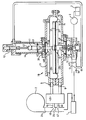
- the accompanying drawing represents partly diagrammatically and partly in cross-section one example of a flow regulating device embodying the invention, together with associated apparatus for conveying a fluid fuel and air to a burner.
- the apparatus illustrated in the accompanying drawing comprises a burner 1 which would, typically, be mounted in a wall of a furnace (not shown).
- a blower 2 For supplying air to the burner, there is provided a blower 2 and for feeding an oil fuel to the burner, there is provided a pump 3 associated with a bulk supply of oil 4.
- conveying means For conveying air from the blower to the burner and conveying fuel from the pump to the burner, there is provided conveying means which defines respective passages 24 and 18 for the air and fuel and which includes a flow regulating device 10.
- the flow regulating device is shown in some detail in the drawing. Other parts of the apparatus are represented diagrammatically only.
- the rate at which air is supplied to the burner 1 is determined primarily by means of an adjustable throttle (not shown separately) which is incorporated in the blower 2. This rate is varied according to the heat output required from the burner.
- the throttle of the blower may be adjustable steplessly to provide a range of flow rates, the maximum value of which is ten times the minimum value. Even when the setting of the throttle is maintained constant, variations in the rate of air flow to the burner may arise from variations in the air pressure at the blower inlet or variations in the combustion chamber into which the burner 1 fires.
- the regulating device 10 is intended to maintain a predetermined ratio between the rate of flow of air to the burner 1 and the rate of flow of fuel to the burner under all operating conditions.
- the regulating device 10 comprises a hollow body 11 in which there are mounted three diaphragm assemblies 13, 14 and 15 respectively. In the arrangement illustrated, these diaphragm assemblies are spaced apart from one another vertically with one of the outer diaphragm assemblies, 13, being uppermost and the other outer diaphragm assembly, 15, being lowermost.
- the regulating device further comprises a valve member 16 which is disposed within the body 11 and which is movable upwardly and downwardly relative to the body.
- the diaphragm assemblies are horizontal and coaxial with the valve member.
- the diaphragm assembly 14 comprises a diaphragm 14 a and plates 37 between which a central portion of the diaphragm is clamped.
- the diaphragm assemblies 13 and 15 comprise respective diaphragms 13 a and 15 a clamped by respective plates 36 and have at least approximately equal effective areas.
- a peripheral portion of each diaphragm is mounted on the body 11 in a fluid-tight manner.
- the valve member 16 includes a plunger 17 on which central parts of the diaphragms are mounted by means of the clamping plates 36 and 37, also in a fluid-tight manner.
- the plunger is of solid construction and the combination of plunger and diaphragm assemblies is therefore adapted to prevent leakage of fluid between the chambers 28 and 29 and between these intermediate chambers and outer chambers lying beyond the diaphragm assemblies 13 and 15 respectively.
- the means defining an orifice 25 In the air flow passage 24 leading from the blower 2 to the burner 1, there is provided means defining an orifice 25. Respective sensing stations 45 and 47 in the air flow passage upstream and downstream of the orifice 25 are connected with the chambers 28 and 29. This connection may be direct or, as illustrated, indirect.
- the chamber 28 is defined between a downwardly facing surface of the upper diaphragm assembly 13, an upwardly fcing surface of the intermediate diaphragm assembly 14 and adjacent inwardly facing surfaces of the body 11. In a part of the body at the periphery of the chamber 28, there is formed a through bore 5.
- the chamber 29 is defined between an upwardly facing surface of the lower diaphragm assembly 15, a downwardly facing surface of the intermediate diaphragm assembly and adjacent inwardly facing surfaces of the body, a through bore 6 extending from one of these surfaces of the body to the exterior of the body.
- the through bores 5 and 6 are connected via a known fluid pressure amplifier 48 with respective branch passages 44 and 46 communicating with the air flow passage at the sensing stations.
- branch 44 would lead directly to the bore 5 and the branch 46 directly to the bore 6.
- the fuel flow path 18 from the pump 3 to the burner 1 extends through a part of the body 11.
- a valve seat 22 of the body defines a valve orifice 23 in the fuel flow path 18 and a valve head 19 of the valve member 16 is movable relative to the seat to vary the degree of restriction of the orifice 23.
- the valve head is preferably of tapered form and is engageable with the seat 22 to close the orifice 23.
- the unobstructed area of the orifice 23 can be varied steplessly by upward and downward movement of the valve member 16.
- valve member 16 biasing means which includes springs 40 and 41 disposed above the upper diaphragm assembly 13.
- the spring 41 is coupled at one of its ends with the plunger 17 adjacent to the upper end thereof and is coupled at its other end with an adjustment member 42.
- This adjustment member is mounted in an upper part of the body 11 for screwing towards and away from the lower part of the body to vary the tension in the spring 41.
- the adjustment member 42 is externally threaded and forms a part of a screw and nut mechanism for adjustment of the tension in the spring 41.
- This mechanism further comprises an internally threaded bush 57 which is in threaded engagement with the adjustment member and extends through an aperture in an upper end of the body 11 so that torque can be applied to the bush at a position outside the body.
- the central bore of the bush is sealed off by a plug carried on that part of the bush which lies outside the body.
- the spring 40 is subject to compression and acts between an upper plate of the upper diaphragm assembly 13 and a ring 43 provided in the body 11 and restrained against movement away from a lower part of the body by a sleeve 44. There is no provision for adjustment of the compression of spring 40, although small changes in the degree of compression of this spring will occur when the valve member moves upwardly and downwardly relative to the body.
- the spring 41 counteracts the weight of the plunger assembly 17. Adjustment of the position of the adjusting member 42 relative to the body 11 enables the position of the valve head 19 to be adjusted to a selected position relative to the seat 22 when the respective flow rates of air and fuel are zero or under any other conditions which occur during use of the apparatus.
- the valve orifice 23 leads from an inlet of the regulating device to the chamber 31.
- the chamber 31 communicates directly with a sensing station in the fuel flow path upstream of the orifice 49.
- a fourth chamber 30 is defined by an upwardly facing surface of the upper diaphragm assembly 13 and by adjacent surfaces of the body 11. This fourth chamber is connected by a duct 50 with a sensing station in the fuel flow passage 18 downstream of the orifice 49.
- a fourth chamber 30 is defined by an upwardly facing surface of the upper diaphragm assembly 13 and by adjacent surfaces of the body 11. This fourth chamber is connected by a duct 50 with a sensing station in the fuel flow passage 18 downstream of the orifice 49.
- One or both of the orifices 25 and 49 may be adjustable, so that they enable the ratio of the rates of flow of fuel and air along the paths 18 and 24 to be set to a required value.
- X the effective surface area of the upper and lower diaphragm assemblies
- Y the surface area of the middle diaphragm assembly.
- the net opening force due to the pressure of air in the first and second chambers is substantially equal and opposite to the net closing force due to the pressure of fuel in the third and fourth chambers, that is:
- the ratio is a constant. Since P F is a measure of the rate of flow of fuel along the second flow passage 18 and P A is a measure of the rate of flow of air along the first flow passage 24, it can be seen that the ratio of these rates of flow is a constant.
- the device ensures that the ratio remains a constant when one of the rates of flow (that of the air) is changed. It is assumed that under all conditions of operation, the rates of flow of air and fuel are such that the pressure drop across each of the orifices 25 and 49 is proportional to the square of the flow rate concerned. It is also assumed that the effective areas of the outer diaphragm assemblies 13 and 15 are equal.
- the fuel exerts a thrust on the valve head 19.
- the pressure on the valve head does not disturb the required relation between the air flow rate and the fuel flow rate.
- compensation for the effect of the pressure exerted by the fuel on the valve head 19 is achieved by providing outer diaphragm assemblies 13 and 15 with slightly different effective areas. The difference in effective area is of the same order as the minimum cross-sectional area of that part of the valve member 16 which is exposed to the fuel in the chamber 31 and the valve orifice 23. This part of the valve member 16 constitutes a stem on which the head 19 is carried.
- the orifice 23 and the valve head 19 are both small and the difference between the effective areas of the outer diaphragm assemblies is a small fraction of the effective area of one of these, not more than 5% and typically 1%.
- Apparatus in accordance with the present invention may be used for supplying a gaseous fuel and air to a burner.
- the apparatus illustrated in the accompanying drawing would be modified somewhat.
- the pump 3 and oil tank 4 would be omitted, the fuel inlet of the regulating device being connected directly to a gas main.
- the burner 1 would be a gas burner and the cross-sectional area of the fuel flow passage 18 would be increased, as compared with the cross-sectional area which is necessary for the supply of a liquid fuel.
- the size of the orifice 23 and the size of the valve head 19 also would be increased considerably and the fluid pressure amplifier 48 could be omitted.
- the relation between the effective area of the intermediate diaphragm assembly 14 and the upper diaphragm assembly 13 would be changed, these areas either being more nearly equal or the area of the intermediate assembly being smaller than that of each of the outer diaphragm assemblies.
- the difference between the effective area of the lower diaphragm assembly 15 and the effective are of the upper diaphragm assembly 13 may be somewhat greater than 5% of the area of one of these.
- the rate of fuel flow along the passage 18 is correspondingly changed. If the rate of flow of air is increased, the pressure difference between the chambers 28 and 29 is increased and the downwardly directed force exerted on the valve member 17 is increased so that the equilibrium of the valve member 16 is lost. The valve member tends to move downwardly, thereby opening the orifice 23 further and permitting an increased rate of flow of fuel along the path 18. In consequence of this, the pressure difference between the chambers 30 and 31 is increased until the upwardly directed force exerted on the valve member is exactly equal once more to the downwardly directed force and the valve member assumes an equilibrium condition in a new position relative to the body 11. If the rate of flow of air along the path 24 is decreased, the equilibrium of the valve member 16 is lost once more, until the rate of flow of fuel also has been reduced by a corresponding amount.
- the regulating device is able to compensate for changes in conditions in either of the air flow path 24 and the fuel flow path 18. This is in contrast with known devices intended for controlling the rate of flow of fuel to a burner, for example the devices disclosed in U.S. 3,101,897A and in G.B. 120,076A hereinbefore mentioned which do not compensate for changes in conditions in the fuel flow path.
- valve seat 22 is screwed into a bore in an adjacent part of the body in a direction from the chamber 31 towards the exterior of the body.
- the body may be modified so that the valve seat can be screwed into the body in the opposite direction, the external wall of the body being provided with an access opening normally closed by a plug.
- the head 19 of the valve also may be demountable from the valve member so that the valve head can be withdrawn through the access opening, when the plug has been removed.
- the means defining the air orifice 25 are disposed outside the body 11. Although the means defining the fuel orifice 49 is represented in the drawing as being outside the body 11, this orifice may be provided in the device 10. The fuel orifice is spaced along the fuel flow passage from the valve orifice 23. It will further be noted that fluid is admitted to each of the chambers 28 to 31 through an opening in a fixed wall of that chamber defined by a respective part of the body 10. To avoid resistance to movement of the valve member 16 arising from deflection of the diaphragms, the diaphragms are of roll-up form.
- the effective area of the intermediate diaphragm assembly is approximately 17 times the effective area of each outer diaphragm assembly.
- the ratio between the area of the intermediate diaphragm assembly and the area of one outer diaphragm assembly may be increased to a value such that the pressure amplifier is not required and the chambers 28 and 29 can be connected directly with the air flow path.
- the effective areas of the outer diaphragm assemblies 13 and 15 differ from each other by an amount not exceeding the area of the valve head 19, as viewed in the direction of movement of the valve member relative to the body.
Landscapes
- Engineering & Computer Science (AREA)
- Chemical & Material Sciences (AREA)
- Combustion & Propulsion (AREA)
- Mechanical Engineering (AREA)
- General Engineering & Computer Science (AREA)
- Regulation And Control Of Combustion (AREA)
- Heat-Pump Type And Storage Water Heaters (AREA)
- Fluid-Driven Valves (AREA)
- Paper (AREA)
Applications Claiming Priority (2)
| Application Number | Priority Date | Filing Date | Title |
|---|---|---|---|
| GB8229806 | 1982-10-19 | ||
| GB8229806 | 1982-10-19 |
Related Parent Applications (2)
| Application Number | Title | Priority Date | Filing Date |
|---|---|---|---|
| EP83110124A Division EP0110071B1 (de) | 1982-10-19 | 1983-10-11 | Durchflussregeleinrichtung |
| EP83110124A Division-Into EP0110071B1 (de) | 1982-10-19 | 1983-10-11 | Durchflussregeleinrichtung |
Publications (1)
| Publication Number | Publication Date |
|---|---|
| EP0298149A1 true EP0298149A1 (de) | 1989-01-11 |
Family
ID=10533684
Family Applications (2)
| Application Number | Title | Priority Date | Filing Date |
|---|---|---|---|
| EP87112172A Withdrawn EP0298149A1 (de) | 1982-10-19 | 1983-10-11 | Durchflussregeleinrichtung |
| EP83110124A Expired EP0110071B1 (de) | 1982-10-19 | 1983-10-11 | Durchflussregeleinrichtung |
Family Applications After (1)
| Application Number | Title | Priority Date | Filing Date |
|---|---|---|---|
| EP83110124A Expired EP0110071B1 (de) | 1982-10-19 | 1983-10-11 | Durchflussregeleinrichtung |
Country Status (5)
| Country | Link |
|---|---|
| US (1) | US4626194A (de) |
| EP (2) | EP0298149A1 (de) |
| AT (1) | ATE39564T1 (de) |
| CA (1) | CA1224710A (de) |
| DE (1) | DE3378782D1 (de) |
Families Citing this family (12)
| Publication number | Priority date | Publication date | Assignee | Title |
|---|---|---|---|---|
| GB2186962B (en) * | 1986-02-26 | 1990-03-21 | Mor Flo Ind Inc | Forced draft controlled mixture heating system using a closed combustion chamber |
| US4766883A (en) * | 1986-02-26 | 1988-08-30 | Mor-Flo Industries, Inc. | Forced draft controlled mixture heating system using a closed combustion chamber |
| EP0275568A1 (de) * | 1987-01-23 | 1988-07-27 | Furigas Assen B.V. | Gas-gefeuerte Warmwassereinrichtung und mit einem Luftversorgungsventilator und einer Gas/Luft modulierenden Steuerung ausgerüstet |
| US5022352A (en) * | 1990-05-31 | 1991-06-11 | Mor-Flo Industries, Inc. | Burner for forced draft controlled mixture heating system using a closed combustion chamber |
| US5085579A (en) * | 1991-03-25 | 1992-02-04 | Mor-Flo Industries, Inc. | Powered chamber combustion system and burner therefor |
| DE59304310D1 (de) * | 1993-09-16 | 1996-11-28 | Honeywell Bv | Regeleinrichtung für Gasbrenner |
| US5860411A (en) * | 1997-03-03 | 1999-01-19 | Carrier Corporation | Modulating gas valve furnace control method |
| US6835062B2 (en) * | 2001-12-14 | 2004-12-28 | Suntec Industries Incorporated | Fuel oil supply circuit for an oil burner having a solenoid valve in parallel circuit with diaphragm valve for controlling oil flow at start up |
| US7628590B2 (en) * | 2005-02-16 | 2009-12-08 | Sterling Investments Lc | Method and apparatus for reducing free flow risk |
| US20080124667A1 (en) | 2006-10-18 | 2008-05-29 | Honeywell International Inc. | Gas pressure control for warm air furnaces |
| US7832327B2 (en) * | 2007-12-07 | 2010-11-16 | Fisher Controls International Llc | Ring sealed diaphragm |
| EP2868970B1 (de) | 2013-10-29 | 2020-04-22 | Honeywell Technologies Sarl | Regelungsvorrichtung |
Citations (9)
| Publication number | Priority date | Publication date | Assignee | Title |
|---|---|---|---|---|
| GB120076A (en) * | 1917-10-20 | 1918-10-21 | James Keith | Improved Apparatus for Maintaining Proportional Delivery of Gas and Air to Gas-fired Furnaces. |
| DE430846C (de) * | 1924-05-07 | 1926-06-24 | Kurt Rummel Dr Ing | Vorrichtung zur Mengenmessung mittels Hilfsstromes |
| DE834016C (de) * | 1950-03-17 | 1952-03-13 | Rudolf Majert G M B H | Einrichtung zur Regelung eines Gemisches aus zwei Gasen |
| US2886968A (en) * | 1948-03-17 | 1959-05-19 | Rolls Royce | Devices sensitive to the ratio between fluid pressures |
| US3101897A (en) * | 1960-12-29 | 1963-08-27 | Suburban Appliance Company | Control for burners |
| FR1574868A (de) * | 1967-05-15 | 1969-07-18 | ||
| FR2264999A1 (de) * | 1974-03-20 | 1975-10-17 | Sauter Ag | |
| DE2708858A1 (de) * | 1977-03-01 | 1978-09-07 | Caloric Ges Apparatebau | Regeleinrichtung fuer einen brenner fuer fliessfaehige brennstoffe |
| US4302178A (en) * | 1980-02-11 | 1981-11-24 | Maxon Corporation | Variable pressure valve |
Family Cites Families (8)
| Publication number | Priority date | Publication date | Assignee | Title |
|---|---|---|---|---|
| GB249590A (en) * | 1925-01-03 | 1926-04-06 | Selas Gas And Engineering Comp | Improvements relating to apparatus for controlling the proportions of gases in mixtures |
| US2067229A (en) * | 1935-03-04 | 1937-01-12 | William T Birch | Relief valve |
| US2482401A (en) * | 1943-07-01 | 1949-09-20 | Niles Bement Pond Co | Carburetor |
| US2565329A (en) * | 1945-10-24 | 1951-08-21 | Niles Bement Pond Co | Carburetor |
| US2558921A (en) * | 1946-01-16 | 1951-07-03 | Niles Bement Pond Co | Carburetor |
| US3085799A (en) * | 1960-03-23 | 1963-04-16 | Alswang Ralph | Theatrical procedure and stage setting therefor |
| US3827849A (en) * | 1971-12-20 | 1974-08-06 | Honeywell Inc | Combustion control apparatus |
| US4020861A (en) * | 1974-08-19 | 1977-05-03 | International Telephone And Telegraph Corporation | Vapor recovery valve |
-
1983
- 1983-10-11 EP EP87112172A patent/EP0298149A1/de not_active Withdrawn
- 1983-10-11 EP EP83110124A patent/EP0110071B1/de not_active Expired
- 1983-10-11 DE DE8383110124T patent/DE3378782D1/de not_active Expired
- 1983-10-11 AT AT83110124T patent/ATE39564T1/de not_active IP Right Cessation
- 1983-10-19 US US06/543,637 patent/US4626194A/en not_active Expired - Fee Related
- 1983-10-19 CA CA000439252A patent/CA1224710A/en not_active Expired
Patent Citations (9)
| Publication number | Priority date | Publication date | Assignee | Title |
|---|---|---|---|---|
| GB120076A (en) * | 1917-10-20 | 1918-10-21 | James Keith | Improved Apparatus for Maintaining Proportional Delivery of Gas and Air to Gas-fired Furnaces. |
| DE430846C (de) * | 1924-05-07 | 1926-06-24 | Kurt Rummel Dr Ing | Vorrichtung zur Mengenmessung mittels Hilfsstromes |
| US2886968A (en) * | 1948-03-17 | 1959-05-19 | Rolls Royce | Devices sensitive to the ratio between fluid pressures |
| DE834016C (de) * | 1950-03-17 | 1952-03-13 | Rudolf Majert G M B H | Einrichtung zur Regelung eines Gemisches aus zwei Gasen |
| US3101897A (en) * | 1960-12-29 | 1963-08-27 | Suburban Appliance Company | Control for burners |
| FR1574868A (de) * | 1967-05-15 | 1969-07-18 | ||
| FR2264999A1 (de) * | 1974-03-20 | 1975-10-17 | Sauter Ag | |
| DE2708858A1 (de) * | 1977-03-01 | 1978-09-07 | Caloric Ges Apparatebau | Regeleinrichtung fuer einen brenner fuer fliessfaehige brennstoffe |
| US4302178A (en) * | 1980-02-11 | 1981-11-24 | Maxon Corporation | Variable pressure valve |
Also Published As
| Publication number | Publication date |
|---|---|
| DE3378782D1 (en) | 1989-02-02 |
| US4626194A (en) | 1986-12-02 |
| ATE39564T1 (de) | 1989-01-15 |
| EP0110071B1 (de) | 1988-12-28 |
| CA1224710A (en) | 1987-07-28 |
| EP0110071A1 (de) | 1984-06-13 |
Similar Documents
| Publication | Publication Date | Title |
|---|---|---|
| EP0110071B1 (de) | Durchflussregeleinrichtung | |
| US3841344A (en) | Gas mixing systems | |
| US3493005A (en) | Constant flow ratio control system for gas flow lines | |
| US5520533A (en) | Apparatus for modulating the flow of air and fuel to a gas burner | |
| US2650607A (en) | Gas flow control apparatus | |
| US4752211A (en) | Flow proportioning system | |
| US3489165A (en) | Inline pressure regulator | |
| US5301713A (en) | Flow control valve having adjustable piston for varying flow rate | |
| US2916047A (en) | Automatic regulation of the rate of flow of a fluid through a pipe or the like | |
| US4893649A (en) | Constant flow rate controller valve | |
| US5971012A (en) | Constant flow control valve having matable piston sleeve and outlet cover | |
| US4809746A (en) | Proportional throttle valve | |
| US4250913A (en) | Pilot mechanism for pressure regulating valve | |
| US2291731A (en) | Pressure regulating system | |
| US5108071A (en) | Laminar flow valve | |
| JPH10503036A (ja) | デッドループ型バイパス弁 | |
| EP0385029B1 (de) | Leitungs-Druckregler | |
| US3762436A (en) | Fluid pressure regulator | |
| US3572359A (en) | Pressure responsive valve | |
| US3425442A (en) | Pressure regulator | |
| US3071146A (en) | Fluid pressure controller with relief valve | |
| US5280805A (en) | Flow control valve having adjustable sleeve for varying flow rate | |
| US5647394A (en) | Control valve | |
| US3734121A (en) | Fluid flow valves | |
| US3805823A (en) | Pressure regulators |
Legal Events
| Date | Code | Title | Description |
|---|---|---|---|
| PUAI | Public reference made under article 153(3) epc to a published international application that has entered the european phase |
Free format text: ORIGINAL CODE: 0009012 |
|
| 17P | Request for examination filed |
Effective date: 19870821 |
|
| AC | Divisional application: reference to earlier application |
Ref document number: 110071 Country of ref document: EP |
|
| AK | Designated contracting states |
Kind code of ref document: A1 Designated state(s): AT BE CH DE FR GB IT LI LU NL SE |
|
| STAA | Information on the status of an ep patent application or granted ep patent |
Free format text: STATUS: THE APPLICATION HAS BEEN WITHDRAWN |
|
| 18W | Application withdrawn |
Withdrawal date: 19891227 |
|
| RIN1 | Information on inventor provided before grant (corrected) |
Inventor name: MILLS, PAUL |