EP0298455A2 - Dispositif pour forger avec une matrice fermée totale - Google Patents
Dispositif pour forger avec une matrice fermée totale Download PDFInfo
- Publication number
- EP0298455A2 EP0298455A2 EP88110793A EP88110793A EP0298455A2 EP 0298455 A2 EP0298455 A2 EP 0298455A2 EP 88110793 A EP88110793 A EP 88110793A EP 88110793 A EP88110793 A EP 88110793A EP 0298455 A2 EP0298455 A2 EP 0298455A2
- Authority
- EP
- European Patent Office
- Prior art keywords
- die
- underside
- upside
- slide
- cam
- Prior art date
- Legal status (The legal status is an assumption and is not a legal conclusion. Google has not performed a legal analysis and makes no representation as to the accuracy of the status listed.)
- Granted
Links
- 238000005242 forging Methods 0.000 title claims abstract description 33
- 230000033001 locomotion Effects 0.000 claims abstract description 5
- 239000002184 metal Substances 0.000 abstract description 7
- 238000010276 construction Methods 0.000 abstract description 2
- 239000007788 liquid Substances 0.000 description 9
- 238000000465 moulding Methods 0.000 description 9
- 230000000149 penetrating effect Effects 0.000 description 7
- 239000002893 slag Substances 0.000 description 7
- 238000002360 preparation method Methods 0.000 description 2
- 239000002994 raw material Substances 0.000 description 2
- 241000239290 Araneae Species 0.000 description 1
- 230000001174 ascending effect Effects 0.000 description 1
- 238000004519 manufacturing process Methods 0.000 description 1
- 238000000034 method Methods 0.000 description 1
- 230000000087 stabilizing effect Effects 0.000 description 1
Images


Classifications
-
- B—PERFORMING OPERATIONS; TRANSPORTING
- B21—MECHANICAL METAL-WORKING WITHOUT ESSENTIALLY REMOVING MATERIAL; PUNCHING METAL
- B21J—FORGING; HAMMERING; PRESSING METAL; RIVETING; FORGE FURNACES
- B21J9/00—Forging presses
- B21J9/02—Special design or construction
-
- B—PERFORMING OPERATIONS; TRANSPORTING
- B21—MECHANICAL METAL-WORKING WITHOUT ESSENTIALLY REMOVING MATERIAL; PUNCHING METAL
- B21K—MAKING FORGED OR PRESSED METAL PRODUCTS, e.g. HORSE-SHOES, RIVETS, BOLTS OR WHEELS
- B21K1/00—Making machine elements
- B21K1/76—Making machine elements elements not mentioned in one of the preceding groups
- B21K1/762—Coupling members for conveying mechanical motion, e.g. universal joints
-
- B—PERFORMING OPERATIONS; TRANSPORTING
- B21—MECHANICAL METAL-WORKING WITHOUT ESSENTIALLY REMOVING MATERIAL; PUNCHING METAL
- B21J—FORGING; HAMMERING; PRESSING METAL; RIVETING; FORGE FURNACES
- B21J13/00—Details of machines for forging, pressing, or hammering
- B21J13/02—Dies or mountings therefor
-
- B—PERFORMING OPERATIONS; TRANSPORTING
- B21—MECHANICAL METAL-WORKING WITHOUT ESSENTIALLY REMOVING MATERIAL; PUNCHING METAL
- B21J—FORGING; HAMMERING; PRESSING METAL; RIVETING; FORGE FURNACES
- B21J5/00—Methods for forging, hammering, or pressing; Special equipment or accessories therefor
- B21J5/02—Die forging; Trimming by making use of special dies ; Punching during forging
Definitions
- the present invention relates to a full enclosed die forging apparatus and more particularly a full enclosed die forging apparatus provided with a die moving mechanism which has both punches operate to rush into dies, respectively, by moving a die maintained with contact following the movement of a slide toward a punch on a fixed side at a speed slower than the moving speed of the slide.
- a reference numeral 11 denotes a molded article
- 13 denotes a slag
- 15 denotes an upper die
- 17 denotes a lower die
- 23 denotes an upper punch
- 25 denotes a lower punch
- 33 denotes a slide of a press
- 34 denotes a bolster
- 35 denotes a bed
- 36 denotes an upper pressure pin
- 37 denotes a lower pressure pin.
- the slag 13 is charged by hand or by a feeding device into a cavity 38 of the lower die 17.
- the slide 33 of the press descends, the upper and lower dies 15 and 17 come in contact with each other.
- the slide 33 is urged downwardly by means of a hydraulic device, and in a mechanical press, the slide 33 stops at the bottom dead center, thereby to apply enclosing force to the upper and lower dies 15 and 17.
- a hydraulic unit which is of a different system from the unit for driving the slide 33 installed on the side of the slide 33 and on the side of the bed 35 is operated.
- a driving unit installed separately from the unit for driving the slide 33 is operated in the same manner as in the case of the hydraulic press. With this,the upper and lower pressure pins 36 and 37 are operated, the upper and lower punches 23 and 25 are moved toward above-mentioned cross-section 31, and the slag 13 is pushed out for working toward the cavity 29 formed by the upper and lower dies 15 and 17.
- the slide 33 is ascended and the upper and lower dies 15 and 17 are separated.
- the upper and lower punches 23 and 25 are operated by the hydraulic unit, and the molded article 11 is discharged out of the die.
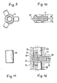
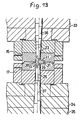
- Fig. 14 shows a full enclosed die forging apparatus disclosed in said Publication.
- the left half of the Figure shows a state when full enclosing is commenced, and the right half thereof shows the state when molding is completed at the bottom dead point.
- an upside die set plate 61 is fixed to a slide 60 of the press, and an insert plate 62 is inserted into this upside die set plate 61 with positioning by a knock pin 63.
- a cushion pin 65 is urged downwardly by installing a cushion rod 64 which is urged downwardly by pressure liquid so as to ascend and descend freely.
- a knockout rod 66 is provided in the slide 60 so as to ascend and descend freely.
- An upside die holder 67 is fixed to the upside die set plate 61, a cam holder 68 is fixed to this die holder 67, and furthermore, a first cam 69 is fixed to the cam holder 68. Besides, this first cam 69 drives the lower die through a second, a third and a fourth cams which will be described later.
- An upper die 70 is fitted to the inside of the upside die holder 67 so as to ascend and descend freely.
- a punch block 71 and an upper punch 72 are fitted to the inside of this upper die 70 so as to ascend and descend freely.
- an underside die set plate 74 is fixed to a bolster 73, and an insert plate 75 is inserted into this die set plate 74.
- a knockout rod 76 is provided so as to push up a knockout pin 77 at a constant timing by receiving a pushing-up force by pressure liquid or a mechanical device.
- a cushion rod 78 is provided so as to urge a cushion pin 79 in the insert plate 75 upwardly.
- an underside die hole 80 is positioned and fixed with a knock pin 81, and a plate 83 is positioned and inserted into this die holder 80 through a knock pin 82.
- pats 84 and 85 are built in, and a spring 86 is installed under compressed condition between these pats 84 and 85.
- this spring 86 urges a lower die which is described later upwardly through a pressure pin 87 penetrating the plate 83 and said pat 84.
- a cushion ring 88 is disposed so as to ascend and descend freely, and the urging force of the cushion pin 79 is arranged so as to be conveyed to a lower die 90 from a pressure pin 89 through this cushion ring 88.
- a die anvil 92 penetrating a punch block 91 so as to ascend and descend freely is provided, and a lower punch 93 is pushed up with a predetermined timing receiving pushing-up action of a knockout pin 77 by attaching a lower punch 93 on the upper part of the punch block 93.
- a guide 95 for guiding a second cam 94, etc. is fixed to said underside die holder 80.
- This second cam 94 is held by fitting slidably at a bore portion of the guide 95 having a circular form, and the bore portion of this cam 94 is fitted to the lower die 90.
- a step portion 94a of the cam 94 is engaged with the step portion of the lower die 90, and then the cam 94 is held by fitting slidably in a vertical direction only in a guide groove 96 along the center of the die 90.
- a third and a fourth cams 97 and 98 which are held slidably in a circumferential direction only by the lower die 90 and the guide 95 are provided between the first cam 69 and the second cam 94.
- the second cam 94 moves downwardly through the third and the fourth cams 97 and 98.
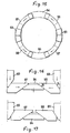
- Fig. 15 through Fig. 17 are drawings showing the locations and operating condition of these cams.
- two pieces of the first cams 69 are provided at diagonal locations of the cam holder 68 and formed in a cleat shape contructing downwardly and the inclined faces of these first cams 69 are made to face between end inclined faces of adjacent third and fourth cams 97 and 98 from the upper part.
- the second cam 94 is provided at a location the phase of which is shifted from the first cam69 by 90° and formed in a cleat shape expanding downwardly, and by having the inclined surface face between point inclined faces of the third and the fourth cams 97 and 98 from the lower part, the third and the fourth cams 97 and 98 are moved in a circumferential direction thereby to push the second cam downwardly when the first cam 69 descends.
- the base ends of the third and the fourth cams 97 and 98 are formed into inclined faces going upwardly and the point ends are formed into inclined faces going downwardly.
- the slag inserted into the cavity of the lower die 90 is formed under a condition that upper and lower dies 70 and 90 are fully enclosed, and is taken out by the operation of the knockout pin 77, etc.
- the descending speed of this die 90 is made slower than the descending speed of the punch 72 by setting the angle of each cam face at a predetermined angle, and upper and lower punches 72 and 93 move relatively to upper and lower dies 70 and 90.
- the first cam 69 is attached to the mold forming member of the upper mold and ascends and descends together with the slide, a cam mechanism is disposed on the outer circumference of the lower die 90, and the spring 86, etc. is disposed in the die holder 80. Accordingly, handling of the apparatus is troublesome, a big clearance is required between the slide 60 and the bolster 73 because the apparatus rises high, and it takes time for replacement of the mold unit.
- a full enclosed die forging apparatus provided with an upside die and an underside die disposed oppositely in a vertical direction between a slide and a bolster, an upside cylinder mechanism which urges said upside die downwardly, an underside cylinder mechanism which urges said underside die upwardly, an upside punch which is inserted in said upside die and moves synchronously with the movement of said slide, an underside punch which is inserted into said underside die and supported by said bolster, and a cam mechanism having both punches operated to rush into dies, respectively, by moving said upside die and underside die toward the underside punch at a speed slower than the moving speed of said slide, wherein said upside cylinder mechanism is contained in said slide, and said underside cylinder mechanism is contained in said bolster.
- opposing upside die and underside die are urged and maintained with contact during molding, respectively, by means of the upside cylinder mechanism and the underside cylinder mechanism contained in the slide and the bolster, respectively. Then, the upside punch inserted through the upside die slidably is moved toward the underside punch. At this time, the upside die and the underside die which are maintained with contact are moved toward the underside punch at a speed lower than the moving speed of the slide, and the upside punch and the underside punch are operated to rush into the upside die and the underside die, respectively.
- Fig. 1 shows an embodiment of a full enclosed die forging apparatus according to the present invention.
- an upside cylinder 140 is formed in a slide 139, and an upside piston 141 is inserted into this upside cylinder 140.
- An upside insert plate 142 is fixed with a bolt 143 to the slide 139, and an upside die set plate 144 is fixed to the lower face of the slide 139.
- An upside actuating pin 145 is disposed on the lower face of the upside piston 141, and the lower end of this upside actuating pin 145 abuts against the upper face of an upside die 146 through a pin 186 provided slidably penetrating the upside die plate 144.
- An upside punch 147 is inserted at the central portion of the upside die 146, and a cavity 148 corresponding to the shape of an article 11 to be molded is formed at the lower part of this upside die 146.
- a knockout pin 149 is disposed so as to ascend and descend freely.
- An upside die holder 150 is fixed to the lower face of the upside die set plate 144, and an upside guide 151 for guiding the upside die 146 is disposed on the lower face of this upside die holder 150.
- an underside die set plate 153 is fixed to a bolster plate 188 of the press.
- An underside cylinder 154 is formed in a bolster 152 provided under the bolster plate 188, and an underside piston 155 is inserted into this underside cylinder 154.
- a step portion is formed on the underside piston 155, and an auxiliary cylinder 189 is formed between the piston 155 and the bolster 152.
- a cam mechanism 156 which will be described later is disposed on this underside piston 155.
- An underside actuating pin 157 is disposed on the upper face of the underside piston 155, and the upper end of this underside actuating pin 157 abuts against the lower face of an underside die 161 through a pin 187 provided slidably penetrating through the underside die set plate 153.
- An underside die holder 158 is fixed to the underside die set plate 153 with a bolt 160, and an underside guide 162 for guiding the underside die 161 is disposed on the upper part of this underside die holder 158.
- An underside punch 159 is inserted at the central portion of the underside die 161, and a cavity 163 corresponding to the shape of the article 11 to be molded is formed at the upper part of the underside die 161.
- a knockout pin 164 is disposed so as to ascend and descend freely.
- a cam mechanism 156 for moving this underside piston 155 is disposed in the underside piston 155.
- This cam mechanism 156 is operated in such a manner that the upper die 146 and the underside die 161 that are maintained with contact are moved toward an underside punch 159 on the fixed side pursuant to the movement of the slide 139 at a speed lower than the moving speed of the slide 139, thereby to have upper and lower punches 147 and 159 rush into upper and lower dies 146 and 161, respectively.
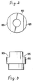
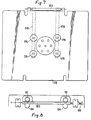
- cutout portions 165 are formed at two locations at angles of 180° on the upper part of the underside piston 155 as shown in Fig. 2 and Fig. 3. Further, plates 167 both sides of which a cam face 166 is formed are placed at these cutout portions 165 as shown in Fig. 4 and Fig. 5.
- cam face 172 of the vertical cam 171 in a plate form abuts against the cam face 170 formed at another end of the horizontal cam 168.
- This push pin 173 is disposed penetrating through the bolster plate 188, and the upper part thereof abuts against the lower face of a pin 190 which is inserted into a support member 174 fixed to the underside die set plate 153.
- a pin 175 abuts against the upper face of this pin 190, and the upper part of this pin 175 abuts against the lower face of a piston 191 which is inserted into a cylinder 176 disposed in the slide 139.
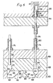
- a cam 177 is disposed on the upper face of the cylinder 176 for controlling the lower face of the piston 191, and a cam face 179 of a cam rod 178 abuts against this cam 177 as shown in Fig. 6 and Fig. 7.
- the cam 177 is urged upwardly by means of a spring 192.
- a female screw portion 180 is formed at an end of the cam rod 178, and a male screw portion 182 of a shaft rod fixed with a pinion gear 181 is screw-engaged with this female screw portion 180.
- a rack 183 is screw-engaged with the pinion gear 181, and this rack 183 is supported by rollers 184.
- a screw shaft 185 By rotating a screw shaft 185 abutting against both ends of the rack 183, it is possible to adjust the lower face position of the piston 191, thereby to adjust dimensions H1 and H2 (Fig. 10) of the molded article 11.
- the slag inserted into the cavity 163 of the underside die 161 is formed under fully enclosed state produced by the upside die 146 and the underside die 161 abutting against each other and is taken out by the action of the knockout pin, etc.
- the lower face of the pin 175 and the upper face of the pin 190 abut against each other when the upside die 146 and the underside die 161 come into contact with each other.
- the underside die 161 descends at a speed lower than that of the upside punch 147 as the upside punch 147 descends, and the upside punch 147 and the underside punch 159 move relatively to the upside die 146 and the underside die 161.
- the underside punch 159 does not move. Therefore, when the slide 139 is made to descend, the upside punch 147 and the underside punch 159 rush into the upside die 146 and the underside die 161, respectively, so as to move closely, thereby to perform expected molding.
- both of angles of the vertical cam 171 and the horizontal cam 168, ⁇ and ⁇ may be selected at 35 degrees 15 minutes 52 seconds theoretically.
- P S auxiliary cylinder
- the upside cylinder 140 mechanism is contained in the slide 139 and the underside cylinder 154 mechanism is contained in the bolster 152. Accordingly, the structures of the die set and the metal die may be simplified, replacement and preparation of the metal die are made easier, and further, the clearance between the slide 139 and the bolster 152 may be reduced by a large margin as compared with a conventional case.
- the underside piston 155 is moved directly by the cam mechanism 156. Therefore, it is possible to reduce the number of parts, and also to surely move the upside die 146 and the underside die 161.
- the upper face of the cylinder 176 is made to abut against the lower face of the cam 177, thereby to determine the vertical position of the cylinder 176. Therefore, by rotating the screw shaft 185 through the rack 183 and the pinion 181 so as to adjust the horizontal position of the cam rod 178, fine adjustment of positions of lower faces of four pieces of pistons 191 may be made at the same time, and dimensional adjustment of molded articles also becomes possible.
- cam mechanism 156 is disposed in the bolster 152.
- present invention is not limited to such an embodiment, but it is possible to inspect and maintain the cam mechanism 156 easily by disposing the cam mechanism 156 in the bolster plate 188.
- the upside cylinder mechanism is contained in the slide, and the underside cylinder mechanism is also contained in the bolster. Accordingly, the die set and the metal die may be structured simply, replacement and preparation become easy, and furthermore, it is possible to reduce the clearance between the slide and the bolster by a large margin as compared with a conventional case.
Landscapes
- Engineering & Computer Science (AREA)
- Mechanical Engineering (AREA)
- Forging (AREA)
Applications Claiming Priority (4)
| Application Number | Priority Date | Filing Date | Title |
|---|---|---|---|
| JP168318/87 | 1987-07-06 | ||
| JP16831887 | 1987-07-06 | ||
| JP63105812A JPH0716749B2 (ja) | 1987-07-06 | 1988-04-28 | 閉塞鍛造装置 |
| JP105812/87 | 1988-04-28 |
Publications (3)
| Publication Number | Publication Date |
|---|---|
| EP0298455A2 true EP0298455A2 (fr) | 1989-01-11 |
| EP0298455A3 EP0298455A3 (en) | 1989-06-14 |
| EP0298455B1 EP0298455B1 (fr) | 1991-10-02 |
Family
ID=26446043
Family Applications (1)
| Application Number | Title | Priority Date | Filing Date |
|---|---|---|---|
| EP88110793A Expired - Lifetime EP0298455B1 (fr) | 1987-07-06 | 1988-07-06 | Dispositif pour forger avec une matrice fermée totale |
Country Status (7)
| Country | Link |
|---|---|
| US (1) | US4918967A (fr) |
| EP (1) | EP0298455B1 (fr) |
| JP (1) | JPH0716749B2 (fr) |
| KR (1) | KR910006497B1 (fr) |
| CA (1) | CA1298723C (fr) |
| DE (1) | DE3865253D1 (fr) |
| ES (1) | ES2027349T3 (fr) |
Cited By (1)
| Publication number | Priority date | Publication date | Assignee | Title |
|---|---|---|---|---|
| CN100371103C (zh) * | 2004-02-16 | 2008-02-27 | 福光企业股份有限公司 | 锻造部品成型机的无间隙滑座装置 |
Families Citing this family (7)
| Publication number | Priority date | Publication date | Assignee | Title |
|---|---|---|---|---|
| US5177991A (en) * | 1991-07-28 | 1993-01-12 | Presnet Corporation | Method of and apparatus for coining tapers at opposite ends of a sleeve member |
| US6698267B1 (en) * | 2000-04-28 | 2004-03-02 | Morphic Technologies Aktiebolag | Method and impact machine for forming a body |
| DE10047467C5 (de) * | 2000-09-21 | 2009-08-06 | Schuler Pressen Gmbh & Co. Kg | Vorrichtung und Verfahren zum Umformen, insbesondere mit hydraulischer Schließvorrichtung |
| CN107900270B (zh) * | 2017-12-28 | 2019-06-11 | 烟台台海材料科技有限公司 | 一种铰链梁整体模锻成型组合模具及其加工铰链梁方法 |
| CN111922275A (zh) * | 2020-06-12 | 2020-11-13 | 中煤北京煤矿机械有限责任公司 | 一种用于中缸活塞头锻件加工的模具 |
| CN116511412B (zh) * | 2023-05-24 | 2025-10-31 | 无锡英沪标准紧固件有限公司 | 铝镇静钢锻造设备 |
| CN117086246A (zh) * | 2023-08-07 | 2023-11-21 | 无锡派鑫航空科技有限公司 | 一种食品行业离心机转鼓体模锻的制造方法 |
Family Cites Families (6)
| Publication number | Priority date | Publication date | Assignee | Title |
|---|---|---|---|---|
| CH617368A5 (en) * | 1977-05-06 | 1980-05-30 | Supervis Ets | Method for the production of a workpiece by extrusion, application of the method and an apparatus for carrying out the method |
| US4274276A (en) * | 1978-07-31 | 1981-06-23 | Etablissement Supervis | Method and apparatus for producing a workpiece by extrusion molding |
| US4463590A (en) * | 1982-02-25 | 1984-08-07 | The Harris-Thomas Drop Forge Company | Forging method |
| JPS59133927A (ja) * | 1983-01-19 | 1984-08-01 | Aida Eng Ltd | 閉塞鍛造装置 |
| JPS59147732A (ja) * | 1983-02-10 | 1984-08-24 | Aida Eng Ltd | 閉塞鍛造方法 |
| JPS59229298A (ja) * | 1983-05-25 | 1984-12-22 | Komatsu Ltd | プレス機械の金型装置 |
-
1988
- 1988-04-28 JP JP63105812A patent/JPH0716749B2/ja not_active Expired - Fee Related
- 1988-07-01 US US07/214,334 patent/US4918967A/en not_active Expired - Lifetime
- 1988-07-06 EP EP88110793A patent/EP0298455B1/fr not_active Expired - Lifetime
- 1988-07-06 ES ES8888110793T patent/ES2027349T3/es not_active Expired - Lifetime
- 1988-07-06 KR KR1019880008353A patent/KR910006497B1/ko not_active Expired
- 1988-07-06 CA CA000571307A patent/CA1298723C/fr not_active Expired - Fee Related
- 1988-07-06 DE DE8888110793T patent/DE3865253D1/de not_active Expired - Fee Related
Cited By (1)
| Publication number | Priority date | Publication date | Assignee | Title |
|---|---|---|---|---|
| CN100371103C (zh) * | 2004-02-16 | 2008-02-27 | 福光企业股份有限公司 | 锻造部品成型机的无间隙滑座装置 |
Also Published As
| Publication number | Publication date |
|---|---|
| KR890001657A (ko) | 1989-03-28 |
| JPH01104437A (ja) | 1989-04-21 |
| US4918967A (en) | 1990-04-24 |
| JPH0716749B2 (ja) | 1995-03-01 |
| KR910006497B1 (ko) | 1991-08-27 |
| DE3865253D1 (de) | 1991-11-07 |
| EP0298455B1 (fr) | 1991-10-02 |
| EP0298455A3 (en) | 1989-06-14 |
| ES2027349T3 (es) | 1992-06-01 |
| CA1298723C (fr) | 1992-04-14 |
Similar Documents
| Publication | Publication Date | Title |
|---|---|---|
| EP0298456B1 (fr) | Dispositif pour forger avec une matrice fermée totale | |
| CN114653809B (zh) | 一种导向间隙自动调整的冲压模具及冲压方法 | |
| EP0298455A2 (fr) | Dispositif pour forger avec une matrice fermée totale | |
| JPH0341249B2 (fr) | ||
| EP0298457B1 (fr) | Dispositif pour forger avec une matrice fermée totale | |
| US5669128A (en) | Index-feed machining system | |
| RU2125497C1 (ru) | Штамп для выдавливания деталей с глухой полостью (варианты) | |
| JP6395664B2 (ja) | プレス装置、および成形品の製造方法 | |
| JPH0566218B2 (fr) | ||
| JPH06102238B2 (ja) | 閉塞鍛造装置 | |
| KR0171973B1 (ko) | 베벨기어 성형장치 및 그 성형방법 | |
| JPS63224833A (ja) | 成形用金型 | |
| JPS59133927A (ja) | 閉塞鍛造装置 | |
| CN218743996U (zh) | 一种挺杆毛坯冷挤压模具 | |
| CN112872137B (zh) | 一种汽车座椅上横梁内扣折弯成型装置 | |
| SU1224081A1 (ru) | Штамп дл безоблойной штамповки | |
| JPH0442026Y2 (fr) | ||
| JPS59147732A (ja) | 閉塞鍛造方法 | |
| CN118143145A (zh) | 一种可调节式冲压模具及其调节方法 | |
| JPH0339771B2 (fr) | ||
| JP2002018548A (ja) | 鍛造方法及び鍛造装置 | |
| JPH0474107B2 (fr) | ||
| JPS6227915B2 (fr) | ||
| JPH11800A (ja) | パンチプレス | |
| JPH0712444U (ja) | 粉末成形用の上多段パンチ金型装置 |
Legal Events
| Date | Code | Title | Description |
|---|---|---|---|
| PUAI | Public reference made under article 153(3) epc to a published international application that has entered the european phase |
Free format text: ORIGINAL CODE: 0009012 |
|
| AK | Designated contracting states |
Kind code of ref document: A2 Designated state(s): CH DE ES FR GB IT LI |
|
| PUAL | Search report despatched |
Free format text: ORIGINAL CODE: 0009013 |
|
| AK | Designated contracting states |
Kind code of ref document: A3 Designated state(s): CH DE ES FR GB IT LI |
|
| 17P | Request for examination filed |
Effective date: 19890511 |
|
| 17Q | First examination report despatched |
Effective date: 19900503 |
|
| GRAA | (expected) grant |
Free format text: ORIGINAL CODE: 0009210 |
|
| AK | Designated contracting states |
Kind code of ref document: B1 Designated state(s): CH DE ES FR GB IT LI |
|
| ITF | It: translation for a ep patent filed | ||
| REF | Corresponds to: |
Ref document number: 3865253 Country of ref document: DE Date of ref document: 19911107 |
|
| ET | Fr: translation filed | ||
| REG | Reference to a national code |
Ref country code: ES Ref legal event code: FG2A Ref document number: 2027349 Country of ref document: ES Kind code of ref document: T3 |
|
| PG25 | Lapsed in a contracting state [announced via postgrant information from national office to epo] |
Ref country code: ES Free format text: LAPSE BECAUSE OF NON-PAYMENT OF DUE FEES Effective date: 19920707 |
|
| PLBI | Opposition filed |
Free format text: ORIGINAL CODE: 0009260 |
|
| 26 | Opposition filed |
Opponent name: PRESTA PRESS- UND STANZWERK AG Effective date: 19920701 |
|
| PGFP | Annual fee paid to national office [announced via postgrant information from national office to epo] |
Ref country code: GB Payment date: 19930630 Year of fee payment: 6 |
|
| PGFP | Annual fee paid to national office [announced via postgrant information from national office to epo] |
Ref country code: CH Payment date: 19930715 Year of fee payment: 6 |
|
| PGFP | Annual fee paid to national office [announced via postgrant information from national office to epo] |
Ref country code: FR Payment date: 19930716 Year of fee payment: 6 |
|
| PGFP | Annual fee paid to national office [announced via postgrant information from national office to epo] |
Ref country code: DE Payment date: 19930928 Year of fee payment: 6 |
|
| PG25 | Lapsed in a contracting state [announced via postgrant information from national office to epo] |
Ref country code: GB Effective date: 19940706 |
|
| PG25 | Lapsed in a contracting state [announced via postgrant information from national office to epo] |
Ref country code: LI Effective date: 19940731 Ref country code: CH Effective date: 19940731 |
|
| GBPC | Gb: european patent ceased through non-payment of renewal fee |
Effective date: 19940706 |
|
| PG25 | Lapsed in a contracting state [announced via postgrant information from national office to epo] |
Ref country code: FR Effective date: 19950331 |
|
| REG | Reference to a national code |
Ref country code: CH Ref legal event code: PL |
|
| PG25 | Lapsed in a contracting state [announced via postgrant information from national office to epo] |
Ref country code: DE Effective date: 19950401 |
|
| REG | Reference to a national code |
Ref country code: FR Ref legal event code: ST |
|
| PLBN | Opposition rejected |
Free format text: ORIGINAL CODE: 0009273 |
|
| STAA | Information on the status of an ep patent application or granted ep patent |
Free format text: STATUS: OPPOSITION REJECTED |
|
| 27O | Opposition rejected |
Effective date: 19951203 |
|
| REG | Reference to a national code |
Ref country code: ES Ref legal event code: FD2A Effective date: 19930811 |
|
| PG25 | Lapsed in a contracting state [announced via postgrant information from national office to epo] |
Ref country code: IT Free format text: LAPSE BECAUSE OF NON-PAYMENT OF DUE FEES;WARNING: LAPSES OF ITALIAN PATENTS WITH EFFECTIVE DATE BEFORE 2007 MAY HAVE OCCURRED AT ANY TIME BEFORE 2007. THE CORRECT EFFECTIVE DATE MAY BE DIFFERENT FROM THE ONE RECORDED. Effective date: 20050706 |
|
| APAH | Appeal reference modified |
Free format text: ORIGINAL CODE: EPIDOSCREFNO |