EP0299089A1 - Geschwindigkeitsregler - Google Patents
Geschwindigkeitsregler Download PDFInfo
- Publication number
- EP0299089A1 EP0299089A1 EP88901313A EP88901313A EP0299089A1 EP 0299089 A1 EP0299089 A1 EP 0299089A1 EP 88901313 A EP88901313 A EP 88901313A EP 88901313 A EP88901313 A EP 88901313A EP 0299089 A1 EP0299089 A1 EP 0299089A1
- Authority
- EP
- European Patent Office
- Prior art keywords
- velocity
- servomotor
- mechanical load
- distal end
- observer
- Prior art date
- Legal status (The legal status is an assumption and is not a legal conclusion. Google has not performed a legal analysis and makes no representation as to the accuracy of the status listed.)
- Withdrawn
Links
Images
Classifications
-
- H—ELECTRICITY
- H02—GENERATION; CONVERSION OR DISTRIBUTION OF ELECTRIC POWER
- H02P—CONTROL OR REGULATION OF ELECTRIC MOTORS, ELECTRIC GENERATORS OR DYNAMO-ELECTRIC CONVERTERS; CONTROLLING TRANSFORMERS, REACTORS OR CHOKE COILS
- H02P5/00—Arrangements specially adapted for regulating or controlling the speed or torque of two or more electric motors
-
- G—PHYSICS
- G05—CONTROLLING; REGULATING
- G05B—CONTROL OR REGULATING SYSTEMS IN GENERAL; FUNCTIONAL ELEMENTS OF SUCH SYSTEMS; MONITORING OR TESTING ARRANGEMENTS FOR SUCH SYSTEMS OR ELEMENTS
- G05B19/00—Program-control systems
- G05B19/02—Program-control systems electric
- G05B19/18—Numerical control [NC], i.e. automatically operating machines, in particular machine tools, e.g. in a manufacturing environment, so as to execute positioning, movement or co-ordinated operations by means of program data in numerical form
- G05B19/19—Numerical control [NC], i.e. automatically operating machines, in particular machine tools, e.g. in a manufacturing environment, so as to execute positioning, movement or co-ordinated operations by means of program data in numerical form characterised by positioning or contouring control systems, e.g. to control position from one programmed point to another or to control movement along a programmed continuous path
- G05B19/21—Numerical control [NC], i.e. automatically operating machines, in particular machine tools, e.g. in a manufacturing environment, so as to execute positioning, movement or co-ordinated operations by means of program data in numerical form characterised by positioning or contouring control systems, e.g. to control position from one programmed point to another or to control movement along a programmed continuous path using an incremental digital measuring device
- G05B19/23—Numerical control [NC], i.e. automatically operating machines, in particular machine tools, e.g. in a manufacturing environment, so as to execute positioning, movement or co-ordinated operations by means of program data in numerical form characterised by positioning or contouring control systems, e.g. to control position from one programmed point to another or to control movement along a programmed continuous path using an incremental digital measuring device for point-to-point control
- G05B19/231—Numerical control [NC], i.e. automatically operating machines, in particular machine tools, e.g. in a manufacturing environment, so as to execute positioning, movement or co-ordinated operations by means of program data in numerical form characterised by positioning or contouring control systems, e.g. to control position from one programmed point to another or to control movement along a programmed continuous path using an incremental digital measuring device for point-to-point control the positional error is used to control continuously the servomotor according to its magnitude
- G05B19/232—Numerical control [NC], i.e. automatically operating machines, in particular machine tools, e.g. in a manufacturing environment, so as to execute positioning, movement or co-ordinated operations by means of program data in numerical form characterised by positioning or contouring control systems, e.g. to control position from one programmed point to another or to control movement along a programmed continuous path using an incremental digital measuring device for point-to-point control the positional error is used to control continuously the servomotor according to its magnitude with speed feedback only
-
- H—ELECTRICITY
- H02—GENERATION; CONVERSION OR DISTRIBUTION OF ELECTRIC POWER
- H02P—CONTROL OR REGULATION OF ELECTRIC MOTORS, ELECTRIC GENERATORS OR DYNAMO-ELECTRIC CONVERTERS; CONTROLLING TRANSFORMERS, REACTORS OR CHOKE COILS
- H02P6/00—Arrangements for controlling synchronous motors or other dynamo-electric motors using electronic commutation dependent on the rotor position; Electronic commutators therefor
- H02P6/14—Electronic commutators
- H02P6/16—Circuit arrangements for detecting position
- H02P6/17—Circuit arrangements for detecting position and for generating speed information
-
- G—PHYSICS
- G05—CONTROLLING; REGULATING
- G05B—CONTROL OR REGULATING SYSTEMS IN GENERAL; FUNCTIONAL ELEMENTS OF SUCH SYSTEMS; MONITORING OR TESTING ARRANGEMENTS FOR SUCH SYSTEMS OR ELEMENTS
- G05B2219/00—Program-control systems
- G05B2219/30—Nc systems
- G05B2219/42—Servomotor, servo controller kind till VSS
- G05B2219/42162—Model reference adaptive control MRAC, correction fictive-real error, position
Definitions
- This invention relates to a velocity control apparatus for controlling the velocity of the distal end of a load, such as the arm of a robot, by a status observing apparatus.
- Servomotors are used in control systems for driving various mechanical loads in machine tools and the like. In the case of a servomotor for driving a load having little rigidity such as a robot arm, it is required that velocity be controlled and not just position.
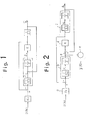
- Fig. 2 is a block diagram illustrating an example of a servo-control system having a mechanical load with little rigidity.
- a servo-controller a is included in a control system constructed such that a servomotor b and a mechanical load c are connected by a spring constant (K) d.
- Kt denotes a torque constant, Jm rotor inertia
- K the spring constant, i L load inertia and 1/s an integration term.
- a current command u(k) applied to the control system is converted into a torque command by the torque constant Kt and a deviation signal between this torque command and an actual torque value is applied to the servomotor b as a command.
- This deviation signal is converted into an acceleration command by the rotor inertia term Jm, and this command is passed through the integration term once to obtain a motor velocity command signal V for driving and controlling the servomotor b to indirectly control the mechanical load c.
- the motor velocity command signal V is passed through the integration term to obtain a position command signal 0, which decides velocity V L and position 8 L on the side of the mechanical load c.
- a rotary encoder e or the like Connected to an output shaft of the servomotor b is a rotary encoder e or the like for detecting, as a command signal y, the commanded position of the mechanical load c commanded by the servomotor b.
- the status variables are reproduced by the observer from a control input and a measurement output.
- the estimated value of velocity based on the servomotor b and the position of the distal end of the mechanical load c is computed and discrete value control is carried out by a microprocessor.
- the following computation equations serve as a basis for estimated values ⁇ , V of position and velocity of the motor and estimated values ⁇ L , v L of the position and velocity of the load used in this computation: where K 1 - K 4 are the gains of the observer.
- the present invention has been devised to solve the aforementioned problems and its object is to provide a velocity control apparatus capable of simply computing estimated values of motor velocity and the velocity of the distal end of a mechanical load by improving upon the construction of an observer.
- a velocity control apparatus for estimating velocity of a motor from a detected position signal and controlling travelling velocity of a mechanical load the movement whereof is controlled by the motor, comprising a servomotor for driving the mechanical load, a servo-controller for subjecting the servomotor to discrete-value control in dependence upon a position of a distal end of the mechanical load, and an observer for computing an estimated value as a deviation between rotational velocity of the servomotor and velocity of the distal end of the mechanical load based on a difference value in an amount of rotation of the servomotor every fixed period.
- the velocity control apparatus of the present invention is such that, with regard to a servo system for driving and controlling a load with little rigidity such as a robot arm by a servomotor, a difference value every fixed period of a number of pulses from a rotary encoder mounted on a shaft of the servomotor is regarded as motor rotational velocity inclusive of detection noise, and accurate velocity control can be realized in which computations for estimating the velocity of the motor and of the distal end of the mechanical load are carried out in a short period of time.
- Fig. 1 is a block diagram illustrating an embodiment of a servo-control system according to the present invention
- Fig. 2 is a block diagram illustrating an example of a conventional servo-control system.
- Fig. 1 is a block diagram in which a model serving as the object of control of an observer according to the invention is reconstructed by a simplified servo-control system.
- a characterizing feature of this simplified model is that status variables are reduced by one by obtaining a deviation between the velocity V L of the distal end of the mechanical load in Fig. 2 and the velocity V of the servomotor from an actual servo-control system.
- discrete-value control by microprocessor is carried out by computing a difference value in the amount of rotation of the servomotor b every fixed period from the detection value y of the rotary encoder e, which is mounted on the shaft of the servomotor b, in accordance with
- the estimated values V and ⁇ o of motor velocity and position and the estimated value V L of the velocity of the distal end of the mechanical load at this time are expressed as follows, in which it is unnecessary to estimate the position ⁇ L of the distal end of the machine: where Kl - K 3 are the gains of the observer and the status matrix of the discrete value system is expressed by Eqs. (13) - (16).
- velocity control would be performed upon evaluating a matricial equation of four rows and four columns.
- control is possible by evaluating a matricial equation of three rows and three columns.
- microprocessor processing time is shortened and predetermined velocity control can be carried out upon obtaining the rotational velocity, from which noise has been removed, of the motor and of the distal end of the mechanical load.
- the velocity control apparatus of the present invention is capable of carrying out optimum control by estimating undetectable physical quantities when driving, by means of a servomotor or the like, a mechanical load having little rigidity.
Landscapes
- Engineering & Computer Science (AREA)
- Power Engineering (AREA)
- Human Computer Interaction (AREA)
- Manufacturing & Machinery (AREA)
- Physics & Mathematics (AREA)
- General Physics & Mathematics (AREA)
- Automation & Control Theory (AREA)
- Feedback Control In General (AREA)
- Control Of Electric Motors In General (AREA)
- Control Of Position Or Direction (AREA)
- Manipulator (AREA)
Applications Claiming Priority (2)
| Application Number | Priority Date | Filing Date | Title |
|---|---|---|---|
| JP19385/87 | 1987-01-29 | ||
| JP62019385A JPS63190583A (ja) | 1987-01-29 | 1987-01-29 | 速度制御方式 |
Publications (1)
| Publication Number | Publication Date |
|---|---|
| EP0299089A1 true EP0299089A1 (de) | 1989-01-18 |
Family
ID=11997830
Family Applications (1)
| Application Number | Title | Priority Date | Filing Date |
|---|---|---|---|
| EP88901313A Withdrawn EP0299089A1 (de) | 1987-01-29 | 1988-01-29 | Geschwindigkeitsregler |
Country Status (5)
| Country | Link |
|---|---|
| US (1) | US4904915A (de) |
| EP (1) | EP0299089A1 (de) |
| JP (1) | JPS63190583A (de) |
| KR (1) | KR890700961A (de) |
| WO (1) | WO1988005977A1 (de) |
Families Citing this family (6)
| Publication number | Priority date | Publication date | Assignee | Title |
|---|---|---|---|---|
| JPH02297602A (ja) * | 1989-05-12 | 1990-12-10 | Fanuc Ltd | 非線形項補償を含むスライディングモード制御方式 |
| US5371449A (en) * | 1991-03-20 | 1994-12-06 | Hitachi, Ltd. | Servo control method for a servo system |
| JPH04308901A (ja) * | 1991-04-05 | 1992-10-30 | Nec Corp | 状態推定器と磁気ディスク装置の位置決め制御回路 |
| JP3296527B2 (ja) * | 1994-08-05 | 2002-07-02 | 株式会社安川電機 | モータ速度制御装置 |
| JP3481004B2 (ja) * | 1995-02-02 | 2003-12-22 | ファナック株式会社 | 外乱オブザーバを使用したバックラッシュ補正方法 |
| JP6445079B2 (ja) * | 2017-04-26 | 2018-12-26 | ファナック株式会社 | サーボモータ制御装置、及び、サーボモータ制御システム |
Family Cites Families (15)
| Publication number | Priority date | Publication date | Assignee | Title |
|---|---|---|---|---|
| JPS5425196B2 (de) * | 1972-03-16 | 1979-08-25 | ||
| US4156835A (en) * | 1974-05-29 | 1979-05-29 | Massachusetts Institute Of Technology | Servo-controlled mobility device |
| DE2802224C2 (de) * | 1978-01-19 | 1982-06-09 | Siemens AG, 1000 Berlin und 8000 München | Schaltungsanordnung zur proportional-integralen Drehzahlregelung einer von einem Elektromotor angetriebenen Arbeitsmaschine mit veränderlicher Belastung |
| US4243923A (en) * | 1979-01-22 | 1981-01-06 | Massachusetts Institute Of Technology | Servo-controlled mobility device |
| US4331910A (en) * | 1980-02-04 | 1982-05-25 | Fujitsu Fanuc Limited | Positioning control system |
| JPS5846413A (ja) * | 1981-09-14 | 1983-03-17 | Hitachi Ltd | 電気サ−ボ機構 |
| JPS58181115A (ja) * | 1982-04-16 | 1983-10-22 | Fanuc Ltd | 位置制御装置 |
| JPS5932012A (ja) * | 1982-08-17 | 1984-02-21 | Sumitomo Electric Ind Ltd | 位置決めサ−ボ方式 |
| US4547858A (en) * | 1983-06-13 | 1985-10-15 | Allied Corporation | Dynamic control for manipulator |
| US4621332A (en) * | 1983-06-20 | 1986-11-04 | Hitachi, Ltd. | Method and apparatus for controlling a robot utilizing force, position, velocity, spring constant, mass coefficient, and viscosity coefficient |
| US4603284A (en) * | 1984-06-05 | 1986-07-29 | Unimation, Inc. | Control system for manipulator apparatus with resolved compliant motion control |
| JPS61116986A (ja) * | 1984-11-09 | 1986-06-04 | Fanuc Ltd | 速度制御装置 |
| DE3564778D1 (en) * | 1984-12-04 | 1988-10-13 | Siemens Ag | Device and method for controlling an industrial robot |
| JPS61164481A (ja) * | 1985-01-12 | 1986-07-25 | Fanuc Ltd | 速度制御方式 |
| JPS6327904A (ja) * | 1986-07-22 | 1988-02-05 | Hitachi Ltd | サ−ボ機構装置の位置修正制御方式 |
-
1987
- 1987-01-29 JP JP62019385A patent/JPS63190583A/ja active Pending
-
1988
- 1988-01-29 EP EP88901313A patent/EP0299089A1/de not_active Withdrawn
- 1988-01-29 US US07/251,378 patent/US4904915A/en not_active Expired - Fee Related
- 1988-01-29 WO PCT/JP1988/000082 patent/WO1988005977A1/ja not_active Ceased
- 1988-09-29 KR KR1019880701201A patent/KR890700961A/ko not_active Ceased
Non-Patent Citations (1)
| Title |
|---|
| See references of WO8805977A1 * |
Also Published As
| Publication number | Publication date |
|---|---|
| US4904915A (en) | 1990-02-27 |
| WO1988005977A1 (fr) | 1988-08-11 |
| JPS63190583A (ja) | 1988-08-08 |
| KR890700961A (ko) | 1989-04-28 |
Similar Documents
| Publication | Publication Date | Title |
|---|---|---|
| EP0208788A1 (de) | Geschwindigkeitsregelsystem für servomotoren | |
| US5719479A (en) | Collision detecting method | |
| EP0241563B1 (de) | Regelungssystem der geschwindigkeit | |
| US4617502A (en) | Method and apparatus for controlling a robot hand along a predetermined path | |
| EP0201605A1 (de) | System zum regeln der geschwindigkeit eines servomotors | |
| EP0247206B1 (de) | Regelungssystem für die geschwindigkeit | |
| EP0292575B1 (de) | Regelanordnung mit servolenkung | |
| EP0514847B1 (de) | System und Verfahren zur Geschwindigkeitsregelung von elektrischen Motoren in extrem niedrigen Geschwindigkeitsbereichen unter Verwendung eines rotierenden Pulskodierers | |
| EP0292574B1 (de) | Numerische regelvorrichtung | |
| JP3545487B2 (ja) | モータで駆動する機械系のイナーシャおよび摩擦トルクの推定方法 | |
| US4904915A (en) | Velocity control apparatus | |
| US5239248A (en) | Servo control system | |
| EP0510212B1 (de) | Verfahren zur steuerung eines servomotors mit vorwärtskopplung | |
| EP0095924B1 (de) | Messmethode und Vorrichtung dafür | |
| JP3481004B2 (ja) | 外乱オブザーバを使用したバックラッシュ補正方法 | |
| US5418439A (en) | Apparatus and method for discriminating position information in a position control system | |
| EP0403658A1 (de) | Geschwindigkeitsregelverfahren für einen servomotor | |
| JPS6337597B2 (de) | ||
| JP3246572B2 (ja) | 電動機駆動系の負荷定数測定方法 | |
| EP0604663A1 (de) | Verfahren zur schätzung von trägheit und stör-drehmoment und verfahren zum erkennen einer unüblichen belastung | |
| JPH06131050A (ja) | サーボモータで駆動される可動部の衝突検出方法 | |
| JP2906255B2 (ja) | サーボ制御装置 | |
| JP2673028B2 (ja) | ロボットの位置決め検出方法 | |
| CN113561170B (zh) | 机器人力矩补偿方法、机器人、设备及存储介质 | |
| JP3171860B2 (ja) | サーボ制御システム |
Legal Events
| Date | Code | Title | Description |
|---|---|---|---|
| PUAI | Public reference made under article 153(3) epc to a published international application that has entered the european phase |
Free format text: ORIGINAL CODE: 0009012 |
|
| 17P | Request for examination filed |
Effective date: 19881003 |
|
| AK | Designated contracting states |
Kind code of ref document: A1 Designated state(s): DE FR GB |
|
| 18W | Application withdrawn |
Withdrawal date: 19891220 |
|
| STAA | Information on the status of an ep patent application or granted ep patent |
Free format text: STATUS: THE APPLICATION HAS BEEN WITHDRAWN |
|
| R18W | Application withdrawn (corrected) |
Effective date: 19891220 |