EP0299113A2 - Herstellungsvorrichtung für Gussprodukte - Google Patents
Herstellungsvorrichtung für Gussprodukte Download PDFInfo
- Publication number
- EP0299113A2 EP0299113A2 EP87117691A EP87117691A EP0299113A2 EP 0299113 A2 EP0299113 A2 EP 0299113A2 EP 87117691 A EP87117691 A EP 87117691A EP 87117691 A EP87117691 A EP 87117691A EP 0299113 A2 EP0299113 A2 EP 0299113A2
- Authority
- EP
- European Patent Office
- Prior art keywords
- filling
- mould
- elastic
- vacuum
- unit
- Prior art date
- Legal status (The legal status is an assumption and is not a legal conclusion. Google has not performed a legal analysis and makes no representation as to the accuracy of the status listed.)
- Granted
Links
Images

Classifications
-
- B—PERFORMING OPERATIONS; TRANSPORTING
- B29—WORKING OF PLASTICS; WORKING OF SUBSTANCES IN A PLASTIC STATE IN GENERAL
- B29C—SHAPING OR JOINING OF PLASTICS; SHAPING OF MATERIAL IN A PLASTIC STATE, NOT OTHERWISE PROVIDED FOR; AFTER-TREATMENT OF THE SHAPED PRODUCTS, e.g. REPAIRING
- B29C33/00—Moulds or cores; Details thereof or accessories therefor
- B29C33/44—Moulds or cores; Details thereof or accessories therefor with means for, or specially constructed to facilitate, the removal of articles, e.g. of undercut articles
- B29C33/48—Moulds or cores; Details thereof or accessories therefor with means for, or specially constructed to facilitate, the removal of articles, e.g. of undercut articles with means for collapsing or disassembling
- B29C33/50—Moulds or cores; Details thereof or accessories therefor with means for, or specially constructed to facilitate, the removal of articles, e.g. of undercut articles with means for collapsing or disassembling elastic or flexible
-
- A—HUMAN NECESSITIES
- A23—FOODS OR FOODSTUFFS; TREATMENT THEREOF, NOT COVERED BY OTHER CLASSES
- A23B—PRESERVATION OF FOODS, FOODSTUFFS OR NON-ALCOHOLIC BEVERAGES; CHEMICAL RIPENING OF FRUIT OR VEGETABLES
- A23B2/00—Preservation of foods or foodstuffs, in general
- A23B2/80—Freezing; Subsequent thawing; Cooling
- A23B2/803—Materials being transported through or in the apparatus, with or without shaping, e.g. in the form of powders, granules or flakes
- A23B2/8033—Materials being transported through or in the apparatus, with or without shaping, e.g. in the form of powders, granules or flakes with packages or with shaping in the form of blocks or portions
-
- A—HUMAN NECESSITIES
- A23—FOODS OR FOODSTUFFS; TREATMENT THEREOF, NOT COVERED BY OTHER CLASSES
- A23G—COCOA; COCOA PRODUCTS, e.g. CHOCOLATE; SUBSTITUTES FOR COCOA OR COCOA PRODUCTS; CONFECTIONERY; CHEWING GUM; ICE-CREAM; PREPARATION THEREOF
- A23G1/00—Cocoa; Cocoa products, e.g. chocolate; Substitutes therefor
- A23G1/04—Apparatus specially adapted for manufacture or treatment of cocoa or cocoa products
- A23G1/20—Apparatus for moulding, cutting or dispensing chocolate
- A23G1/201—Apparatus not covered by groups A23G1/21 - A23G1/28
- A23G1/205—Apparatus in which the material is shaped at least partially in a mould, in the hollows of a surface, a drum or an endless band, or by drop-by-drop casting or dispensing of the material on a surface, e.g. injection moulding or transfer moulding
-
- A—HUMAN NECESSITIES
- A23—FOODS OR FOODSTUFFS; TREATMENT THEREOF, NOT COVERED BY OTHER CLASSES
- A23G—COCOA; COCOA PRODUCTS, e.g. CHOCOLATE; SUBSTITUTES FOR COCOA OR COCOA PRODUCTS; CONFECTIONERY; CHEWING GUM; ICE-CREAM; PREPARATION THEREOF
- A23G1/00—Cocoa; Cocoa products, e.g. chocolate; Substitutes therefor
- A23G1/04—Apparatus specially adapted for manufacture or treatment of cocoa or cocoa products
- A23G1/20—Apparatus for moulding, cutting or dispensing chocolate
- A23G1/22—Chocolate moulds
- A23G1/223—Mould materials
- A23G1/226—Moulds of plastic or elastomeric material, or plastic or elastomer coated moulds
-
- A—HUMAN NECESSITIES
- A23—FOODS OR FOODSTUFFS; TREATMENT THEREOF, NOT COVERED BY OTHER CLASSES
- A23G—COCOA; COCOA PRODUCTS, e.g. CHOCOLATE; SUBSTITUTES FOR COCOA OR COCOA PRODUCTS; CONFECTIONERY; CHEWING GUM; ICE-CREAM; PREPARATION THEREOF
- A23G3/00—Sweetmeats; Confectionery; Marzipan; Coated or filled products
- A23G3/02—Apparatus specially adapted for manufacture or treatment of sweetmeats or confectionery; Accessories therefor
- A23G3/0236—Shaping of liquid, paste, powder; Manufacture of moulded articles, e.g. modelling, moulding, calendering
- A23G3/0252—Apparatus in which the material is shaped at least partially in a mould, in the hollows of a surface, a drum, an endless band, or by a drop-by-drop casting or dispensing of the material on a surface, e.g. injection moulding, transfer moulding
-
- A—HUMAN NECESSITIES
- A23—FOODS OR FOODSTUFFS; TREATMENT THEREOF, NOT COVERED BY OTHER CLASSES
- A23G—COCOA; COCOA PRODUCTS, e.g. CHOCOLATE; SUBSTITUTES FOR COCOA OR COCOA PRODUCTS; CONFECTIONERY; CHEWING GUM; ICE-CREAM; PREPARATION THEREOF
- A23G3/00—Sweetmeats; Confectionery; Marzipan; Coated or filled products
- A23G3/02—Apparatus specially adapted for manufacture or treatment of sweetmeats or confectionery; Accessories therefor
- A23G3/0236—Shaping of liquid, paste, powder; Manufacture of moulded articles, e.g. modelling, moulding, calendering
- A23G3/0252—Apparatus in which the material is shaped at least partially in a mould, in the hollows of a surface, a drum, an endless band, or by a drop-by-drop casting or dispensing of the material on a surface, e.g. injection moulding, transfer moulding
- A23G3/0268—Moulds
- A23G3/0273—Moulds of plastic or elastomeric material, or plastic or elastomer coated moulds
-
- A—HUMAN NECESSITIES
- A23—FOODS OR FOODSTUFFS; TREATMENT THEREOF, NOT COVERED BY OTHER CLASSES
- A23G—COCOA; COCOA PRODUCTS, e.g. CHOCOLATE; SUBSTITUTES FOR COCOA OR COCOA PRODUCTS; CONFECTIONERY; CHEWING GUM; ICE-CREAM; PREPARATION THEREOF
- A23G9/00—Frozen sweets, e.g. ice confectionery, ice-cream; Mixtures therefor
- A23G9/04—Production of frozen sweets, e.g. ice-cream
- A23G9/14—Continuous production
- A23G9/16—Continuous production the products being within a cooled chamber, e.g. drum
-
- A—HUMAN NECESSITIES
- A23—FOODS OR FOODSTUFFS; TREATMENT THEREOF, NOT COVERED BY OTHER CLASSES
- A23P—SHAPING OR WORKING OF FOODSTUFFS, NOT FULLY COVERED BY A SINGLE OTHER SUBCLASS
- A23P30/00—Shaping or working of foodstuffs characterised by the process or apparatus
- A23P30/10—Moulding
-
- B—PERFORMING OPERATIONS; TRANSPORTING
- B29—WORKING OF PLASTICS; WORKING OF SUBSTANCES IN A PLASTIC STATE IN GENERAL
- B29C—SHAPING OR JOINING OF PLASTICS; SHAPING OF MATERIAL IN A PLASTIC STATE, NOT OTHERWISE PROVIDED FOR; AFTER-TREATMENT OF THE SHAPED PRODUCTS, e.g. REPAIRING
- B29C33/00—Moulds or cores; Details thereof or accessories therefor
- B29C33/38—Moulds or cores; Details thereof or accessories therefor characterised by the material or the manufacturing process
- B29C33/40—Plastics, e.g. foam or rubber
- B29C33/405—Elastomers, e.g. rubber
-
- B—PERFORMING OPERATIONS; TRANSPORTING
- B29—WORKING OF PLASTICS; WORKING OF SUBSTANCES IN A PLASTIC STATE IN GENERAL
- B29C—SHAPING OR JOINING OF PLASTICS; SHAPING OF MATERIAL IN A PLASTIC STATE, NOT OTHERWISE PROVIDED FOR; AFTER-TREATMENT OF THE SHAPED PRODUCTS, e.g. REPAIRING
- B29C43/00—Compression moulding, i.e. applying external pressure to flow the moulding material; Apparatus therefor
- B29C43/32—Component parts, details or accessories; Auxiliary operations
- B29C43/36—Moulds for making articles of definite length, i.e. discrete articles
- B29C43/3642—Bags, bleeder sheets or cauls for isostatic pressing
- B29C2043/3652—Elastic moulds or mould parts, e.g. cores or inserts
-
- B—PERFORMING OPERATIONS; TRANSPORTING
- B29—WORKING OF PLASTICS; WORKING OF SUBSTANCES IN A PLASTIC STATE IN GENERAL
- B29C—SHAPING OR JOINING OF PLASTICS; SHAPING OF MATERIAL IN A PLASTIC STATE, NOT OTHERWISE PROVIDED FOR; AFTER-TREATMENT OF THE SHAPED PRODUCTS, e.g. REPAIRING
- B29C43/00—Compression moulding, i.e. applying external pressure to flow the moulding material; Apparatus therefor
- B29C43/32—Component parts, details or accessories; Auxiliary operations
- B29C43/36—Moulds for making articles of definite length, i.e. discrete articles
-
- Y—GENERAL TAGGING OF NEW TECHNOLOGICAL DEVELOPMENTS; GENERAL TAGGING OF CROSS-SECTIONAL TECHNOLOGIES SPANNING OVER SEVERAL SECTIONS OF THE IPC; TECHNICAL SUBJECTS COVERED BY FORMER USPC CROSS-REFERENCE ART COLLECTIONS [XRACs] AND DIGESTS
- Y10—TECHNICAL SUBJECTS COVERED BY FORMER USPC
- Y10S—TECHNICAL SUBJECTS COVERED BY FORMER USPC CROSS-REFERENCE ART COLLECTIONS [XRACs] AND DIGESTS
- Y10S425/00—Plastic article or earthenware shaping or treating: apparatus
- Y10S425/014—Expansible and collapsible
-
- Y—GENERAL TAGGING OF NEW TECHNOLOGICAL DEVELOPMENTS; GENERAL TAGGING OF CROSS-SECTIONAL TECHNOLOGIES SPANNING OVER SEVERAL SECTIONS OF THE IPC; TECHNICAL SUBJECTS COVERED BY FORMER USPC CROSS-REFERENCE ART COLLECTIONS [XRACs] AND DIGESTS
- Y10—TECHNICAL SUBJECTS COVERED BY FORMER USPC
- Y10S—TECHNICAL SUBJECTS COVERED BY FORMER USPC CROSS-REFERENCE ART COLLECTIONS [XRACs] AND DIGESTS
- Y10S425/00—Plastic article or earthenware shaping or treating: apparatus
- Y10S425/044—Rubber mold
Definitions
- the present invention relates to apparatus for producing cast products and in particular to apparatus for producing cast products, wherein non-solid materials such as water; food stuffs including chocolate paste, fish cake, and fish paste; stationaries such as rubber for erasers; and ordinary utensils such as soap are filled in an elastic mould of open-bag shape, and then solidified to yield products.
- non-solid materials such as water
- food stuffs including chocolate paste, fish cake, and fish paste
- stationaries such as rubber for erasers
- ordinary utensils such as soap are filled in an elastic mould of open-bag shape, and then solidified to yield products.
- a variety of materials including food stuffs have been produced by means of molding.
- Conventional moulds have been constructed of a plurality of split moulds made of a rigid body. According to these conventional methods for use of split moulds, the materials are first filled into the split moulds to allow to solidify inside the moulds, and then withdrawn by separating the split moulds.
- the split mould is made of a rigid body, the manufacture of the split mould itself is so expensive that the product cost tends to be high. Especially when a variety of product types but small production rates are necessary, the cost of the split mould occupies a greater part of the total cost of the product, and this virtually prohibits the actual production of the desired items.
- the split mould made of a rigid body often breaks under a high pressure or a vacuum which may be applied to the mould in the solidification step of a material whose volume changes with temperatures.
- An object of the present invention is, therefore, to provide apparatus for producing cast products by the use of an elastic mould of open-bag shape which permits the production of cast products without having such joints as appears in split moulds.
- Another object of this invention is to provide cast-producing apparatus which can accomplish the reduction of the manufacture cost of the mould itself and the prevention of the mould damage.
- a further object of this invention is to provide apparatus for producing cast products wherein materials can be completely filled into small crevices of a mould of even most complicated shape without developing any air bubbles in spite of higher or lower viscosity of the filling material.
- the present invention is characterized in that the apparatus of this invention comprises a filling unit wherein elastic moulds of open-bag shape are filled with non-solid materials, a solidifying unit wherein the materials are allowed to solidify in the elastic moulds, and a withdrawal unit wherein the solidified materials are withdrawn from the inside of the elastic moulds and that the elastic mould in the filling unit is positioned under a vacuum when filling starts.
- materials are first filled into elastic moulds in a filling unit.
- Elastic moulds are used because filled or solidified materials are withdrawn by expanding or contracting the whole moulds in the filling unit or the withdrawal unit.
- the filling into the elastic moulds is carried out when the elastic moulds are positioned under vacuum. Therefore, at the stage of filling, almost no air is present inside the filling section of open-bag shape, and air bubble entrainment of formation in the filling material filled in the filling section can be prevented simply by maintaining the filling material free from the air before filling starts.
- the filling section of open-bag shape can be expanded by applying more vacuum in the opposite side of the entrance of the elastic mould than in the inside of the elastic mould of open-bag shape.
- filling is performed into the moulds thus expanded and afterwards the elastic moulds returns to the original size by equalizing the degrees of vacuum in both sides slowly after or during the filling step. This action beneficially permits the filling into the mould of more elaborate shape.
- the material After being filled into the elastic mould, the material is then solidified in the solidifying unit, which may be a heating or refrigeration unit, depending on the property of the filling material.
- the solidifying unit which may be a heating or refrigeration unit, depending on the property of the filling material.
- a vacuum can be developed in the opposite side of the entrance of the elastic mould in order to expand the elastic mould to withdraw the product.
- the product can be withdrawn by pushing it from the opposite side of the elastic mould entrance.
- Fig. 1 is a block diagram of apparatus.
- Fig. 2 is a perspective view.
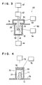
- Fig. 3 is a schematic illustration to show a filling unit, and
- Fig. 4 is a schematic illustration to depict a withdrawal unit.
- Fig. 1 is a block diagram to depict the configuration of the apparatus.
- Fig. 2 is a partial perspective view.
- Figs. 3 and 4 are provided to illustrate each unit individually.
- the present invention comprises a filling unit 40 wherein a filling material 11 is filled into an elastic mould 10, a solidifying unit 60 wherein the material 11 filled in the elastic mould 10 is solidified, and a withdrawal unit 70 wherein the filling material 11 solidified inside the elastic mould 10 is withdrawn.
- These units 40, 60 and 70 are successively arranged along a transfer conveyor 20, and are controlled with a control unit 30.
- the transfer conveyor 20 is driven by a pulley 23 connected with a motor 21 via a reducer 22 and intermittently travels between each unit 40, 60, and 70 at a velocity preset with the control unit 30.
- Each fixing sheet 24 fixed in the transfer conveyor 20 is placed pallarel to the direction of conveyor travel.
- Each fixing sheet 24 has a fixing hole 25 larger than the size of the final product 12.
- the elastic mould 10 comprises an open-bag shaped filling section 13 and a fixing member 14 formed near the open edge of the filling section 13.
- the shape of the filling section 13 is spherical, cylindrical, or patterns of animals or specific characters, and the filling material 11 filled inside the filling section 13 takes the shape of the sphere, cylinder or patterns of the animals or the specific characters after the material is solidified.
- the fixing member 14 is a flange extending from the filling section 13 and fixed in the fixing sheet 24 of the transfer conveyor 20 in order to facilitate the filling material 11 to be filled inside the filling section 13.
- Fig. 3 illustrates an example of the filling unit 40.
- filling in the filling unit 40 is carried out under a vacuum using a vacuum mechanism 50. Both mouth and bottom sections of the elastic mould 10 are placed under a vacuum.
- the vacuum mechanism 50 possesses an upper cover 51 connected with an upper vacuum source 53, and a lower cover 52 connected with a lower vacuum source 54.
- the elastic mould 10 is so positioned that it opens its mouth up-wardly with the filling section 13 hanging down from the fixing sheet 24.
- the upper cover 51 approaches to the elastic mould from above by actuating a first vertical motion mechanism 43 while the lower cover 52 approaches to the elastic mould from below by actuating a second vertical motion mechanism 44.
- a filling nozzle 41 connected with a filling mechanism 42 is fixed to the upper cover 51 so that the filling nozzle 41 moves up and down simultaneously with the upper cover 51.
- the upper and lower covers 51 and 52 move in such a manner that the elastic mould 10 is grasped between both of the covers so that the flow of air to and from the covers 51 and 52 is almost absent since packings(not shown) between the covers tightly shut the air.
- the upper vacuum source 53 and lower vacuum source 54 are equipped with such obvious items as vacuum pumps, valves, and pressure gauges(not shown). After the elastic mould 10 is tightly grasped between the upper cover 51 and lower cover 52, the upper vacuum source 53 and lower vacuum source 54 are operated to develop a vacuum inside the upper cover 51 and lower cover 52. Thus, almost no air is present inside the filling section 13 of open-bag shape. Degrees of vacuum are dependent upon the nature of the filling material 11 and are preferable less than those at which volatile components contained in the filling material 1 evaporate or cause forming.
- the filling nozzle 41 is fixed to the upper cover 51 and that the filling nozzle 41 moves together with the upper cover 51.
- a vertical motion mechanism for the filling nozzle 41 is independent of the first vertical motion mechanism 43 used for the upper cover 51.
- both of the covers 51 and 52 can be integrally constructed though it has been stated that the elastic mould 10 is covered with both of the upper cover 51 and lower cover 52 to be placed under a vacuum.
- the upper vacuum source 53 and lower vacuum source 54 are independent of each other.
- the vacuum source can be common and a vacuum is developed in both of the upper cover 51 and lower cover 52 which are connected with the common vacuum source via a branch pipe.
- Degrees of vacuum can be changed for the chambers covered with the upper cover 51 and lower cover 52.
- the elastic mould 10 expands as it is filled with the filling material 11.
- the elastic mould 10 After being filled, the elastic mould 10 returns to the original size by equalizing the degrees of vacuum or by putting the pressure back to atmospheric pressure.
- the force of contraction pushes the filling material 11 to the smallest crevices of the filling section 13, and this permits the filling into an elastic mould of more elaborate shape.
- vacuums can be developed separately with the use of the upper vacuum source 53 and lower vacuum source 54 as described in this example.
- a single vacuum source can be used with suitable valves to provide a vacuum difference.
- a first vertical motion mechanism 43 for the upper cover 51 is constructed as a separate assembly which is independent of the nozzle vertical motion mechanism for the filling mechanism 42 including the filling nozzle 41. Then, both of the vertical motion mechanisms are controlled in such manners as described hereinafter.
- the filling nozzle 41 of the filling mechanism 42 is made to penetrate through the upper cover 51, lowered in the vicinity of the bottom of the filling section 13 of the elastic mould 10 over the transfer conveyor 20 by means of the vertical motion mechanism 43 to fill the mould partly, and then only the filling nozzle 41 is lifted slowly by the action of the nozzle vertical motion mechanism while filling the material and keeping the upper cover 51 in the same position.
- the filling mechanism 42 may stay in its original position while the elastic mould 10 is moved up and down with the vertical motion mechanism (not shown).
- the elastic mould 10 may stay to be filled by the filling unit 40 and then may be transferred intermittently after completing the filling operation.
- the filling unit 40 may be transferred along the production line to fill the filling material 11 from the filling unit 40.
- a solidifying unit 60 is used to solidify a filling material 11 inside the elastic mould 10.
- This unit is composed of a heating mechanism, a cooling mechanism, a combination of these mechanisms, or other mechanisms.
- the specific configuration of the solidifying unit 60 is dependent on the material of which the filling material 11 is made.
- the solidifying unit 60 can be a cooling unit.
- the filling material 11 is a substance which can solidify upon heating, a solution of protein, fish cake or paste, or rubber for an eraser, for example, the solidifying unit 60 can be a heating unit.
- the filling material 11 is a food-stuff
- cooking is often necessary as well as the step of heating the material 11.
- a cooking unit can then be used in combination with the solidifying unit 60.
- the mould 10 is so elastic that it will not break upon solidification in the solidifying unit 60 even if the material 11 changes its volume.
- the mould when the mould is made of a rigid body, it sometimes breaks because of such internal-pressure increase as encountered in water solidification by cooling. In the present invention, however, no damage or rupture will occur because the elastic mould 10 can expand as its volume increases.
- Fig. 4 shows a withdrawal unit 70 where the solidified product 12 is withdrawn from the inside of the filling section 13 of the elastic mould 10.
- the product 12 can be pushed out by pushing the product 12 from the opposite side of the opening of the elastic mould 10 because of its elasticity.
- the open edge can be extended by an external force before the product 12 is pushed out from the opposite side of the open edge.
- the following withdrawal unit can be used in which no single part of the product 12 is affected by an external force.
- the filling section 13 located underneath the fixing sheet 24 of a transfer conveyor 20 is turned around by a pulley 23 so as to be positioned above the fixing sheet 24, and the cast product 12 inside the mould 10 is allowed to fall to a withdrawal conveyor 71 located below by expanding the filling section 13.
- the cast product 12 can be withdrawn when the filling section 13 is located in a horizontal position.
- the withdrawal unit 70 of this type comprises a rotary shaft 72 rotated with a motor 21, a vacuum cam 73 fixed on the rotary shaft 72, a transmission rod 74 shaken by the vacuum cam rotation, and a vacuum body 75 placed on the edge of the transmission rod 74.
- the rotary shaft 72 is rotated with the same motor 21 in use for driving the transfer conveyor 20 in such a way that each of the other units are synchronized.
- the vacuum cam 73 serves as a front cam fixed on the rotary shaft 72.
- the vacuum unit 75 is connected with vacuum source 76, and is used for maintaining a vacuum chamber 77 inside the vacuum unit 75 in a vacuum state.
- the vacuum source 76 is composed of a vacuum pump, a valve and a pressure gauge, though the detailed drawings are not shown.
- the vacuum chamber 77 has the size of covering the filling section 13 in that the product 12 is contained.
- a cushion 78 is placed on the upper surface of the inside of the vacuum chamber 77.
- the action of the withdrawal unit 70 is as follows. First, the material 11 inside the filling section 13 is solidified in the solidifying unit 60, and afterwards is turned around by the pulley 23. Then, the transfer conveyor 20 intermittently moves so that the filling section 13 containing the solidified product is positioned above the fixing sheet.
- the vacuum chamber 77 now covers the filling section 13, and the inside of the vacuum chamber 77 is evacuated by the vacuum source 76.
- the elastic mould 10 made of an elastic body expands so that it contacts with the inside wall of the vacuum chamber 77.
- the fixing member 14 as well as the filling section 13 of the elastic mould 10 comes in intimate contact with the inside of the vacuum chamber 77, and an opening is shaped around the fixing hole 25 of the fixing sheet 24.
- the product 12 leaves the elastic mould 10 and falls down through the fixing hole 25 of the fixing sheet 24, the hole being larger than the product 12.
- the product is then transferred to a specified position by a withdrawal conveyor 71 placed below the withdrawal unit 70.
- drawing shown as an example provides a cylindrical vacuum chamber 77 with an end cap, a totally or partially tapered chamber(not drawn) is desirable because such shape permits a free falling of the product from the inside of the vacuum chamber 77.
- any shapes of cast products 12 can be produced by preparing a variety of elastic moulds.
- the elastic mould 10 can be mass-produced at low costs.
- the product of the present invention has no such joint as appears in that produced by means of a split mould so that there can be obtained a natural-looking and high-value product. Furthermore, production steps can be simplified because no splits of the mould into a plurality of directions are required.
- the filling section 13 of open-bag shape can be expanded by applying more vacuum in the opposite side of the opening of the elastic mould 10 than in the inside of the elastic mould of open-bag shape.
- the filling of the filling material 11 is carried out into the mould thus expanded, and afterwards the elastic mould 10 returns to the original size by equalizing the degrees of vacuum in both sides slowly after or during the filling steps. This action beneficially permits the filling into the mould of more elaborate shape.
- the elastic mould 10 can expand and contract as the volume of the filling material 11 changes in the solidification step in the solidification unit 60. Hence, the elastic mould 10 will not break at all.
- the shape of the product 12 will not suffer damaged in the withdrawal step, since a vacuum is used for gently withdrawing the product 12 in the withdrawal unit 70.
- the elastic mould 10 can be any elastic material including soft rubber and soft plastic. As long as it is elastic, any material can be used for the mould.
- the open-bag shaped mould of the present invention provides products without joints, low production costs of the mould itself, prevention of mould breakage as well as a great degree of production step simplification.
- the filling material can be filled into the inside of the elastic mould without air bubbles trapped in the filling material.
Landscapes
- Engineering & Computer Science (AREA)
- Life Sciences & Earth Sciences (AREA)
- Chemical & Material Sciences (AREA)
- Food Science & Technology (AREA)
- Polymers & Plastics (AREA)
- Manufacturing & Machinery (AREA)
- Mechanical Engineering (AREA)
- Wood Science & Technology (AREA)
- Zoology (AREA)
- Casting Or Compression Moulding Of Plastics Or The Like (AREA)
- Formation And Processing Of Food Products (AREA)
- Confectionery (AREA)
- Fish Paste Products (AREA)
- Non-Alcoholic Beverages (AREA)
Applications Claiming Priority (2)
| Application Number | Priority Date | Filing Date | Title |
|---|---|---|---|
| JP147709/87 | 1987-06-13 | ||
| JP62147709A JPH0681694B2 (ja) | 1987-06-13 | 1987-06-13 | 充填成型品製造機 |
Publications (3)
| Publication Number | Publication Date |
|---|---|
| EP0299113A2 true EP0299113A2 (de) | 1989-01-18 |
| EP0299113A3 EP0299113A3 (en) | 1989-03-15 |
| EP0299113B1 EP0299113B1 (de) | 1992-07-15 |
Family
ID=15436444
Family Applications (1)
| Application Number | Title | Priority Date | Filing Date |
|---|---|---|---|
| EP87117691A Expired - Lifetime EP0299113B1 (de) | 1987-06-13 | 1987-11-30 | Herstellungsvorrichtung für Gussprodukte |
Country Status (5)
| Country | Link |
|---|---|
| US (1) | US4854843A (de) |
| EP (1) | EP0299113B1 (de) |
| JP (1) | JPH0681694B2 (de) |
| CA (1) | CA1317731C (de) |
| DE (1) | DE3780455T2 (de) |
Cited By (7)
| Publication number | Priority date | Publication date | Assignee | Title |
|---|---|---|---|---|
| EP0429853A3 (en) * | 1989-10-27 | 1991-09-25 | Okamoto Industries, Inc. | Elastic forming die, molding method, and device for forming molded products |
| EP0493197A1 (de) * | 1990-12-20 | 1992-07-01 | L'oreal | Verfahren zum Formen eines fliessfähigen Materials, insbesondere Seifen, und transparente oder durchscheinende Seifen |
| EP0503612A1 (de) * | 1991-03-14 | 1992-09-16 | Akutagawa Confectionary Co., Ltd. | Elastische Form und Verfahren zur Herstellung von Formteilen mit dieser Form |
| EP0516101A1 (de) * | 1991-05-28 | 1992-12-02 | Akutagawa Confectionary Co., Ltd. | Flexible und elastische Giessform und Herstellungsverfahren von dreidimensionale geformten Gegenständen mit bedruckten Munstern |
| WO1993015613A1 (en) * | 1992-02-14 | 1993-08-19 | Gradual Pty., Ltd. | Molding process and apparatus |
| EP0643921A1 (de) * | 1993-09-22 | 1995-03-22 | Asahi Denka Kogyo Kabushiki Kaisha | Verfahren zum Beschicken elastischer Giessformen |
| FR2730662A1 (fr) * | 1995-02-17 | 1996-08-23 | Robin Christian | Procede et dispositif pour la fabrication de pieces moulees en matiere synthetique |
Families Citing this family (15)
| Publication number | Priority date | Publication date | Assignee | Title |
|---|---|---|---|---|
| US5306460A (en) * | 1987-06-13 | 1994-04-26 | Asahi Denka Kogyo K.K. | Method of producing cast products using elastic molds |
| US5032328A (en) * | 1989-11-08 | 1991-07-16 | Griffis Steven C | Method for casting friable asbestos-containing material into a non-friable mass |
| US5213732A (en) * | 1991-01-11 | 1993-05-25 | Milomir Jevtic | Method of casting materials using a flexible resilient mold |
| US5188790A (en) * | 1991-04-30 | 1993-02-23 | Owl Scientific Plastics, Inc. | Casting method for forming a gel matrix |
| JP3525163B2 (ja) * | 1992-07-31 | 2004-05-10 | 旭電化工業株式会社 | 中空成形品の製造方法 |
| JP3272792B2 (ja) * | 1992-12-15 | 2002-04-08 | フクダ電子株式会社 | 超音波カプラ製造方法 |
| JP3393939B2 (ja) * | 1994-12-20 | 2003-04-07 | ポーラ化成工業株式会社 | 固形物成型方法及び装置 |
| US5840348A (en) * | 1995-09-15 | 1998-11-24 | Ultrapure Systems, Inc. | Automated carbon block molding machine and method |
| RU2168905C1 (ru) * | 1999-11-09 | 2001-06-20 | Общество с ограниченной ответственностью Фирма "Кондитер" | Форма для отливки конфет в виде фигурки матрешки |
| RU2289938C1 (ru) * | 2005-05-12 | 2006-12-27 | Дмитрий Георгиевич Иванов | Способ формования шоколадных изделий, способ изготовления формы и форма |
| RU2340199C2 (ru) * | 2006-12-28 | 2008-12-10 | Открытое акционерное общество Московская кондитерская фабрика "Красный Октябрь" | Способ формования фигурного шоколадного изделия и фигурное шоколадное изделие |
| DE102007016188A1 (de) | 2007-02-02 | 2008-08-07 | Marcus Gaudoin | Verfahren und Vorrichtung zur Herstellung eines Gebildes |
| RU2355178C1 (ru) * | 2007-12-19 | 2009-05-20 | Ирина Борисовна Эльдарханова | Способ производства шоколадного изделия сложной конфигурации с высокой детализацией |
| CN102001145B (zh) * | 2010-08-30 | 2015-07-01 | 黎泽荣 | 一种多排浇注机 |
| US12005607B2 (en) * | 2021-02-10 | 2024-06-11 | Applied Physics, Inc. | Airforming constructive system |
Family Cites Families (25)
| Publication number | Priority date | Publication date | Assignee | Title |
|---|---|---|---|---|
| US1124871A (en) * | 1913-05-01 | 1915-01-12 | John J Nigon | Fluid-pressure-controlling mechanism for glass-drawing machines. |
| US1968887A (en) * | 1932-08-17 | 1934-08-07 | American Anode Inc | Method of making rubber articles |
| DE725454C (de) * | 1937-07-24 | 1942-09-23 | Theo Daniels | Verfahren zum Herstellen von Pralinen mit Krem-, Nougat- oder Geleefuellung |
| US2182454A (en) * | 1937-08-09 | 1939-12-05 | Alvin G Sherman | Ice cube tray |
| US2378701A (en) * | 1943-11-16 | 1945-06-19 | Dewey And Almy Chem Comp | Manufacture of articles from liquid dispersions |
| CH274039A (de) * | 1949-05-02 | 1951-03-15 | Oerlikon Maschf | Verfahren zum Vergiessen von unter Atmosphärendruck polymerisierenden Kunstharzen. |
| US2660776A (en) * | 1950-12-01 | 1953-12-01 | John H Miller | Flexible mold for forming statues with spaced legs |
| DE1228781B (de) * | 1954-08-11 | 1966-11-17 | Messwandler Bau Gmbh | Vorrichtung zum Herstellen blasen- und rissefreier Giessharzkoerper |
| FR1366035A (fr) * | 1963-05-06 | 1964-07-10 | Commissariat Energie Atomique | Bourrelet de fabrication de pièces présentant un bourrelet épais ou une bordure à lèvres multiples en un matériau élastomère du genre latex |
| GB1037527A (en) * | 1963-09-24 | 1966-07-27 | Rolls Royce | Improvements in or relating to dies or moulds |
| US3677674A (en) * | 1971-03-09 | 1972-07-18 | Nat Forge Co | High production isostatic molding device |
| GB1370297A (en) * | 1971-11-02 | 1974-10-16 | Olin Energy Systems Ltd | Machine for isostatic moulding |
| BE789210A (fr) * | 1972-01-10 | 1973-01-15 | Nat Forge Cy | Dispositif de moulage isostatique |
| US3815863A (en) * | 1972-06-13 | 1974-06-11 | F Andeweg | Collapsible flexible material candle mold |
| US4093175A (en) * | 1973-10-03 | 1978-06-06 | Precision Flexmold, Inc. | Distensible elastomeric molds |
| GB1508589A (en) * | 1974-03-28 | 1978-04-26 | Unilever Ltd | Forming of ice lollies and other ice confections |
| US3982721A (en) * | 1975-01-20 | 1976-09-28 | Precision Flexmold, Inc. | Molding apparatus including a one-piece flexible mold deformable by fluid pressure differential |
| US3980269A (en) * | 1975-01-20 | 1976-09-14 | Precision Flexmold, Inc. | Molding apparatus including a one-piece flexible mold having male and female forming members |
| IT1036645B (it) * | 1975-02-10 | 1979-10-30 | Ice Cream Engineering Di G Tan | Stampo reversibile per la formatora di gelati, griaccioli e affini cosiroito in materiale elastomero |
| US4055620A (en) * | 1976-09-07 | 1977-10-25 | Conrad Jack R | Flexible mold and process |
| US4051296A (en) * | 1977-03-14 | 1977-09-27 | International Harvester Company | Silicone rubber mold |
| FR2468455A1 (fr) * | 1979-10-30 | 1981-05-08 | Charrin Denis | Procede de moulage de produits fragiles a presentation soignee et de formes nouvelles et dispositif pour sa mise en oeuvre |
| FR2539670B3 (fr) * | 1983-01-26 | 1985-10-25 | Chaudronnees Centre Sa Const | Procede de moulage au moyen d'empreintes a paroi souple, et machine automatique de mise en oeuvre |
| DE3689164D1 (de) * | 1985-10-19 | 1993-11-18 | Komine Rubber Ind Co | Verfahren zur Herstellung einer elastischen Form. |
| US4802839A (en) * | 1986-03-20 | 1989-02-07 | Yoshiyuki Corporation | Apparatus for producing cast products |
-
1987
- 1987-06-13 JP JP62147709A patent/JPH0681694B2/ja not_active Expired - Lifetime
- 1987-11-20 CA CA000552353A patent/CA1317731C/en not_active Expired - Fee Related
- 1987-11-25 US US07/125,430 patent/US4854843A/en not_active Expired - Lifetime
- 1987-11-30 EP EP87117691A patent/EP0299113B1/de not_active Expired - Lifetime
- 1987-11-30 DE DE8787117691T patent/DE3780455T2/de not_active Expired - Lifetime
Cited By (9)
| Publication number | Priority date | Publication date | Assignee | Title |
|---|---|---|---|---|
| EP0429853A3 (en) * | 1989-10-27 | 1991-09-25 | Okamoto Industries, Inc. | Elastic forming die, molding method, and device for forming molded products |
| EP0493197A1 (de) * | 1990-12-20 | 1992-07-01 | L'oreal | Verfahren zum Formen eines fliessfähigen Materials, insbesondere Seifen, und transparente oder durchscheinende Seifen |
| EP0503612A1 (de) * | 1991-03-14 | 1992-09-16 | Akutagawa Confectionary Co., Ltd. | Elastische Form und Verfahren zur Herstellung von Formteilen mit dieser Form |
| EP0516101A1 (de) * | 1991-05-28 | 1992-12-02 | Akutagawa Confectionary Co., Ltd. | Flexible und elastische Giessform und Herstellungsverfahren von dreidimensionale geformten Gegenständen mit bedruckten Munstern |
| WO1993015613A1 (en) * | 1992-02-14 | 1993-08-19 | Gradual Pty., Ltd. | Molding process and apparatus |
| US5558895A (en) * | 1992-02-14 | 1996-09-24 | Gradual Pty Ltd. | Molding process and apparatus |
| EP0643921A1 (de) * | 1993-09-22 | 1995-03-22 | Asahi Denka Kogyo Kabushiki Kaisha | Verfahren zum Beschicken elastischer Giessformen |
| US5698154A (en) * | 1993-09-22 | 1997-12-16 | Asahi Denka Kogyo Kabushikikaisya | Method for charging molding material in elastic molding die |
| FR2730662A1 (fr) * | 1995-02-17 | 1996-08-23 | Robin Christian | Procede et dispositif pour la fabrication de pieces moulees en matiere synthetique |
Also Published As
| Publication number | Publication date |
|---|---|
| DE3780455T2 (de) | 1992-12-17 |
| CA1317731C (en) | 1993-05-18 |
| EP0299113B1 (de) | 1992-07-15 |
| JPH0681694B2 (ja) | 1994-10-19 |
| EP0299113A3 (en) | 1989-03-15 |
| JPS63312119A (ja) | 1988-12-20 |
| US4854843A (en) | 1989-08-08 |
| DE3780455D1 (de) | 1992-08-20 |
Similar Documents
| Publication | Publication Date | Title |
|---|---|---|
| US4854843A (en) | Apparatus for producing cast products | |
| EP0242059B1 (de) | Herstellungsvorrichtung für Gussprodukte | |
| US5306460A (en) | Method of producing cast products using elastic molds | |
| AU740778B2 (en) | Device and process for the metering and suction of viscous products | |
| EP0395756A1 (de) | Vorrichtung zur herstellung von giessprodukten durch füllen der giessformen | |
| EP0318595A1 (de) | Vorrichtung zur herstellung von durch füllen der giessform erzeugten produkten | |
| CA1316659C (en) | Apparatus for producing cast products and process therefor | |
| US6966766B2 (en) | Method and apparatus for producing a shell of a mass containing fat and/or sugar in a mould | |
| CA1319002C (en) | Apparatus for producing cast products and process therefor | |
| JPH0679818B2 (ja) | 充填成型品製造機 | |
| CA1313446C (en) | Apparatus for producing cast products and process therefor | |
| JP2589978B2 (ja) | 充填成型品製造機 | |
| JPS6331726A (ja) | 充填成型品製造機 | |
| JPH0679820B2 (ja) | 充填成型品製造機 | |
| JPH0679819B2 (ja) | 充填成型品製造機 | |
| JPH0679821B2 (ja) | 充填成型品製造機 | |
| JPS63312120A (ja) | 弾性充填型 | |
| JPH0623480U (ja) | アイスクリーム未凍結吸引装置 |
Legal Events
| Date | Code | Title | Description |
|---|---|---|---|
| PUAI | Public reference made under article 153(3) epc to a published international application that has entered the european phase |
Free format text: ORIGINAL CODE: 0009012 |
|
| AK | Designated contracting states |
Kind code of ref document: A2 Designated state(s): CH DE FR GB IT LI NL |
|
| PUAL | Search report despatched |
Free format text: ORIGINAL CODE: 0009013 |
|
| AK | Designated contracting states |
Kind code of ref document: A3 Designated state(s): CH DE FR GB IT LI NL |
|
| 17P | Request for examination filed |
Effective date: 19890523 |
|
| 17Q | First examination report despatched |
Effective date: 19900809 |
|
| GRAA | (expected) grant |
Free format text: ORIGINAL CODE: 0009210 |
|
| ITF | It: translation for a ep patent filed | ||
| AK | Designated contracting states |
Kind code of ref document: B1 Designated state(s): CH DE FR GB IT LI NL |
|
| REF | Corresponds to: |
Ref document number: 3780455 Country of ref document: DE Date of ref document: 19920820 |
|
| ET | Fr: translation filed | ||
| PLBE | No opposition filed within time limit |
Free format text: ORIGINAL CODE: 0009261 |
|
| STAA | Information on the status of an ep patent application or granted ep patent |
Free format text: STATUS: NO OPPOSITION FILED WITHIN TIME LIMIT |
|
| 26N | No opposition filed | ||
| REG | Reference to a national code |
Ref country code: GB Ref legal event code: 746 Effective date: 19970522 |
|
| REG | Reference to a national code |
Ref country code: FR Ref legal event code: D6 |
|
| REG | Reference to a national code |
Ref country code: GB Ref legal event code: IF02 |
|
| REG | Reference to a national code |
Ref country code: CH Ref legal event code: PFA Owner name: ADEKA CORPORATION Free format text: ASAHI DENKA KOGYO KABUSHIKI KAISHA#2-35, HIGASHIOGU 7-CHOME#ARAKAWA-KU/TOKYO (JP) -TRANSFER TO- ADEKA CORPORATION#2-35, HIGASHIOGU 7-CHOME#ARAKAWA-KU, TOKYO (JP) |
|
| PGFP | Annual fee paid to national office [announced via postgrant information from national office to epo] |
Ref country code: FR Payment date: 20061108 Year of fee payment: 20 |
|
| PGFP | Annual fee paid to national office [announced via postgrant information from national office to epo] |
Ref country code: NL Payment date: 20061115 Year of fee payment: 20 |
|
| PGFP | Annual fee paid to national office [announced via postgrant information from national office to epo] |
Ref country code: DE Payment date: 20061123 Year of fee payment: 20 |
|
| PGFP | Annual fee paid to national office [announced via postgrant information from national office to epo] |
Ref country code: GB Payment date: 20061129 Year of fee payment: 20 |
|
| PGFP | Annual fee paid to national office [announced via postgrant information from national office to epo] |
Ref country code: IT Payment date: 20061130 Year of fee payment: 20 Ref country code: CH Payment date: 20061130 Year of fee payment: 20 |
|
| NLT1 | Nl: modifications of names registered in virtue of documents presented to the patent office pursuant to art. 16 a, paragraph 1 |
Owner name: ADEKA CORPORATION |
|
| REG | Reference to a national code |
Ref country code: FR Ref legal event code: CD |
|
| REG | Reference to a national code |
Ref country code: GB Ref legal event code: PE20 |
|
| REG | Reference to a national code |
Ref country code: CH Ref legal event code: PL |
|
| PG25 | Lapsed in a contracting state [announced via postgrant information from national office to epo] |
Ref country code: NL Free format text: LAPSE BECAUSE OF EXPIRATION OF PROTECTION Effective date: 20071130 |
|
| NLV7 | Nl: ceased due to reaching the maximum lifetime of a patent |
Effective date: 20071130 |
|
| PG25 | Lapsed in a contracting state [announced via postgrant information from national office to epo] |
Ref country code: GB Free format text: LAPSE BECAUSE OF EXPIRATION OF PROTECTION Effective date: 20071129 |