EP0299383A2 - Procédé de lecture de feuilles à code d'identification - Google Patents
Procédé de lecture de feuilles à code d'identification Download PDFInfo
- Publication number
- EP0299383A2 EP0299383A2 EP88110945A EP88110945A EP0299383A2 EP 0299383 A2 EP0299383 A2 EP 0299383A2 EP 88110945 A EP88110945 A EP 88110945A EP 88110945 A EP88110945 A EP 88110945A EP 0299383 A2 EP0299383 A2 EP 0299383A2
- Authority
- EP
- European Patent Office
- Prior art keywords
- identification code
- sub
- areas
- representation
- reading
- Prior art date
- Legal status (The legal status is an assumption and is not a legal conclusion. Google has not performed a legal analysis and makes no representation as to the accuracy of the status listed.)
- Granted
Links
Images


Classifications
-
- G—PHYSICS
- G06—COMPUTING OR CALCULATING; COUNTING
- G06K—GRAPHICAL DATA READING; PRESENTATION OF DATA; RECORD CARRIERS; HANDLING RECORD CARRIERS
- G06K19/00—Record carriers for use with machines and with at least a part designed to carry digital markings
- G06K19/06—Record carriers for use with machines and with at least a part designed to carry digital markings characterised by the kind of the digital marking, e.g. shape, nature, code
- G06K19/06009—Record carriers for use with machines and with at least a part designed to carry digital markings characterised by the kind of the digital marking, e.g. shape, nature, code with optically detectable marking
- G06K19/06037—Record carriers for use with machines and with at least a part designed to carry digital markings characterised by the kind of the digital marking, e.g. shape, nature, code with optically detectable marking multi-dimensional coding
-
- G—PHYSICS
- G06—COMPUTING OR CALCULATING; COUNTING
- G06K—GRAPHICAL DATA READING; PRESENTATION OF DATA; RECORD CARRIERS; HANDLING RECORD CARRIERS
- G06K19/00—Record carriers for use with machines and with at least a part designed to carry digital markings
- G06K19/06—Record carriers for use with machines and with at least a part designed to carry digital markings characterised by the kind of the digital marking, e.g. shape, nature, code
- G06K2019/06215—Aspects not covered by other subgroups
- G06K2019/06253—Aspects not covered by other subgroups for a specific application
-
- G—PHYSICS
- G06—COMPUTING OR CALCULATING; COUNTING
- G06K—GRAPHICAL DATA READING; PRESENTATION OF DATA; RECORD CARRIERS; HANDLING RECORD CARRIERS
- G06K19/00—Record carriers for use with machines and with at least a part designed to carry digital markings
- G06K19/06—Record carriers for use with machines and with at least a part designed to carry digital markings characterised by the kind of the digital marking, e.g. shape, nature, code
- G06K2019/06215—Aspects not covered by other subgroups
- G06K2019/06262—Aspects not covered by other subgroups with target- or other orientation-indicating feature
Definitions
- the invention relates, in general, to an identification code sheet and a method of its reading and, more particularly, to an identification code sheet representing a merchandise code, a character string and a document etc. capable of identifying a numerical character, symbol, an alphabet, a Kana-Kanzi character etc., and to a method of its reading enabling reading of the content of identification code from said sheet.
- said bar code is set up by a plurality of fine and thick bars spaced regularly and combined to represent a numerical character etc.
- a sheet of bar code set up by a combination of a plurality of fine and thick bars spaced regularly is characteristically accompanied by such drawbacks as a need of high level technics of printing on the sheet and of printing very costly and requiring unnecessarily high level of accuracy for preparation.
- Another sheet of token code type for binary representation in terms of the locations of punched hole is accompanied by such drawbacks as a need of punching process and a low speed of reading relative to an optical and a magnetic types.
- bar codes are to be identified as to binary codes on the principle of finding both a finess/thickness and a location of the code bars, thus often resulting in a high likelihood of inducing reading errors; these types of codes are mostly to represent, in general, the numerical characters and rarely can handle even the reading covering the alphabets. For this reason, the realization of these conventional means has not so far been achieved to cover a Kanzi-code under JIS (Japanese Industrial Standard) rule.
- Primary object of the invention is a provision of an identification code sheet and a method of its reading, wherein a representation area is defined by both a X-axis and a Y-axis for representation of an identification code, and in said representation area are provided and sub-areas in which said identification code is recorded by means of binary signals.
- a representation area defined by both the X-axis and the Y-axis is represented on an identification code sheet, and needed signal codes are recorded in sub-areas of said representation area, thus providing an identification code.
- an exact reading of signal codes can be attained, without any limitation to the available direction of reading, by virtue of an existence of the representation area, when the identification code is read by means of a senser to read identification codes.
- Another object of the invention is a provision of an identification sheet and a method of its reading, wherein said representation area is divided into at least sixteen or more sub-areas, and in each of which said identification code set up by signal codes in terms of binary signals is recorded.
- a large number of data of 2 factorials can be recorded, and any representation in terms of Kana-Kanzi, Thai, Arabic and Chinese letters etc. as well as numerical characters, symbols and alphbets may be provided and read. And representation on a sheet of an ordinary quality can be made and read at a very high level of accuracy and speed, without need for use of a paper of special quality, availing only a printing means represented by such printer of general purpose type designed for a microcomputer etc.
- Another object of the invention is a provision of an identification code sheet and a method of its reading, wherein sixteen or more sub-areas in said representation area are grouped into four or more assemblies, in which said identification code of 24 or more signal codes is recorded.
- recording and reading can be had in a large versatility, depending on a proper method applied to the selection of the assemblies, thus ensuring an enlargement of an available recording capacity and an ease with which an improved versatility of grouping into the assemblies and added applicability of converting to cipher as well.
- Still further object of the invention is a provision of an identification code sheet and a method of its reading, wherein an auxiliary representation area is provided next to the periphery of said representation area and an auxiliary mark for identification of reading a direction of recorded identification code on said auxiliary representation area is recorded.
- This type of embodiment enables a finding of a representation area's leading end position, trailing end position and vertical and lateral directions of reading made by a sensor to read identification codes and simplifies the pasting of an identification code sheet and to carry out an interpretation at an improved accuracy and higher speed.
- Still further object of the invention is a provision of an identification code sheet and a method of its reading, wherein separation marks are provided between said sub-areas in said representation area in order to be readily interpreted for discrimination.
- sub-areas can be assuredly found by virtue of separation marks to ensure a stabilized interpretation of an identification code, even when there are present an error in printing and an irregularity of the surface of pasting etc.
- FIG.1 is shown an embodiment of the invention in form of a strip of identification code sheet 10.
- Said identification code sheet 10 is a strip of code sheet 12 which may be of either paper or plastic film and the likes.
- an representation area 14 on the face of the identification code sheet 12.
- Said representation area 14 bears the representation area 20 definded by a X-axis 16 and a Y-axis 18 in form orthogonal coordinates, wherein a signal codes 22 is printed to represent identification codes 21 in said representation area 20.
- Said representation area 20 is sub-divided into sixteen sub-areas 24, in each of which a signal code 22 in terms of binary signal codes of 0 or 1 is to be printed; said area 20 may be of various shapes as illustrated in Fig.2.
- Fig.2(a) gives an illustration of the embodiment where a series of signal codes 22 is arranged in a straight line, with length ratio of X-axis 16 to Y-axis 18 of 16:1.
- Fig.2 (b) shows another embodiment where a series of signal codes 22 is arranged in double straight lines, with X-Y axis length ratio of 4:1.
- Fig.2 (c) represents a similar embodiment, with X-Y length ratio of 1:1.
- Figs.2 (d) and (e) give further another embodiment, with X-Y length ratio, contrary to the same of Figs. 2 (a) and (b) of 4:1 and 16:1 respectively, to form a longitudinal elongated shape of sheet.
- the shape of the identification code sheet may be changed properly to meet a particular need case by case as may be found necessary.
- the sub-areas 24 in the reprensetation area 20 are designed, as illustrated in Fig.3, to provide a record of the identification code 21, according to 216 binary codes as represented by 0000, 1000, 2000, ⁇ ⁇ FFFF as illustrated in Fig.4, by arranging P1, P2, P3 ⁇ P16 in a horizontal row and in an appropriate order and addressing them and subsequently making record, in P1, P2, P3 ⁇ P16, of a binary signal of either 0 or 1 as may be found necessary.
- Said binary signal 26 used to print in the individual sub-areas 24 may have various shapes as shown in Fig.5.
- Fig.5 (a) is given an example of mark filling up almost totally a sub-area 24 of a rectangular form
- Figs.5 (b), (c), (d) and (e) show other marks of round, star,triangle and four-dot combination form, with a blank left in the periphery of said sub-area 24.
- a suitable printing means of an ordinary type may be applied, and presently commercially available microcomputor and handy computor or 11- or 24-dot type may also be used for the purpose mentioned.
- name of merchandize, name of section in charge, office address, name of person, telephon number and any other similar character string, message and statement of advertisement may be converted through the microcomputer, according to JIS rule of coding (or the corresponding similar rule of other countries) and a single representation area 20 of one of 216 signal codes 22 for every character.
- identification code 21 it is preferable to have prior representation of the identification code 21 in terms of a character 28 of Kana-Kanzi, English or some other languages as may be found necessary at a location next to the bottom portion or the likes of the representation area 20 for individual signal codes 22, as illustrated in Fig.6, to facilitate a visual confirmation.
- This enables one identification code to be expressed as a single character just equivalent to a single identification code thus providing a clean representation in parallel as shown in Fig.6.
- Fig.7 represents another embodiment of the invention, where a signal code 22 of binary type of the sub-area 24 precedingly mentioned is subdivided in such a manner that, as illustrated, P1 ⁇ P4, P5 ⁇ P8, P9 ⁇ P12 and P13 ⁇ P16 are divided into Q1, Q2, Q3, and Q4 groups resprectively, every groups having four elements. Said four groups are then recorded in terms of four assemblies 30, according to this embodiment.
- the method of sub-division of said sixteen sub-areas 24 into total four groups and sequence of arrangement of the signal codes 22 represented in the assemblies 30 may be selected as may be found necessary: for example, they may be (P1, P6, P11, P16/ P5, P10, P15, P4 / P9, P14, P3, P8 / P2, P7, P12, P13),(P1, P5, P9, P13,/ P14, P15, P16, P12/ P8, P4, P3, P2 / P6, P10, P11, P7),(P1, P2, P6, P5 / P3, P4, P8, P7 / P11, P12, P16, P15 / P9, P10, P14, P13) etc. and some other types of combination as may be found appropriately.
- a representation area 20 is established an auxiliary representation area 36 defined by the extensions 32 and 34 of the X-axis and the Y-axis, as shown is in Fig.8 (a) and (b), represententing an extension of the X-axis 16 and the Y-axis 18, and in a proper location in the said auxiliary area 36, for example the periphery of representation area 20, such as an area diagonal to point of intersection between the X-axis 16 and the Y-axis 18 as illustrated in Fig.8 (a), in order to facilitate the recording an auxiliary mark 38 of a binary signal, as illustrated in Fig.8(b), in the periphery of the representation area 20.
- Said mark 38 needs not be limited to the rectangular shape as illustrated in Fig.8 and may have some other shapes, such as round, star, plus, and minus symbols etc., as may be found necessary.
- identification of the reading direction by a senser is made much more ease and interpretation thereby more exact.
- Conventional inventions are said to involve, in the case of bar code, a failure of reading where reading angle deviates 45° or more away from the standard.
- the embodiment according to the invention ensures stabilized interpretation at a high level of the accuracy, regardless of a directional deviation of pasting of the identification code sheet on the merchandise and the same of reading.
- Fig.9 represents another embodiment of the invention, wherein the representation area 20 is sub-divided by horizontal sub-area separation lines 40 and vertical sub-area separation lines 42, with their separation marks 44 prited at regular intervals.
- sub-areas in representation area may be readily filled up, using a suitable pencil or the likes, to make marks of solid or round etc., and entry of the identification code at the site of operation etc., where the pasting of the identification code sheet and correction of entry having been made can be done with extreme ease, and legiblity may be improved.
- Fig.10 is further another embodiment of the invention, according to which the portions of intersection of horizontal sub-area sparation lines 40 with vertical sub-area separation lines 42 in the representation area 20 shown in Fig.9 are identified with separation marks 44 as illustrated.
- a scope of the sub-area can be known by reading of said separation marks put at every intersection, which, in turn, ensure simplification and speed-up of the separation.
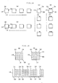
- Fig.11 and Fig.12 are practical examples of the embodiment, respectively.
- Fig.11 are printed, on the identification code sheet 10, representation areas 20 in form of crossed bars, and signal codes 22 and separation marks 44 in rectangular solid blacks, and in Fig.12 are printed out the dots according to the allotment as illustrated, by means of the microcomputer's printer. Any representation most suitable for a printing means may be made according to the embodiments represented by Fig.11 and Fig. 12.
- the identification code sheet has only to be able to be checked to see the presence of a binary signal code for individual sub-areas of representation areas. This means an applicability of paper of ordinary quality to the make of the said sheet and no need for use of a special paper of unusual cost designed for special application, unlike the case with conventinal type bar code. According to the embodiment of the invention, no problem will be encountered in using the identification code sheet, because of reading a binary signal code in the representation area, defined by both the X-axis, and the Y-axis, although the size of code may vary case by case.
- the identification code sheet mentioned above may be applied also to the papers for name card, card, plastic film and the carton's sheet etc. besides the ordinary paper.
- the representation area and the identification code should preferably be represented by printing or with magnetic ink, but conventional technics of conventional punch-type signals are in no case excluded from an application to meet the similar need.
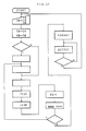
- Fig.15, Fig.16 and Fig.17 concern an example of the method of reading the identification code sheet 10 according to the invention.
- a reading senser 52 such as a bar code reader to read the representation area 20 and signal codes 24 for signal input, followed by subsequent internal processing, result thereof being displayed on an output means 54 of CRT or a printer having been connected as described later.
- said computer 50 comprises a means 56 of determining representation areas, a means 58 of determining sub-areas, a means 60 of determining assemblies, a means 62 of detecting presence of binary signals, a means 64 of converting binary codes and a means 66 of converting codes for output means, the circuit thereof being set up by IC, LSI and the likes, respectively.
- Said means 56 of determining representation areas is set up, as illustrated in Fig.16, by a means 68 of determining the X-axis, a means 70 of determining the Y-axis and a means 72 of correcting a direction of X-axis in order to enable the detection of the representation area 20 of the identification code sheet 10 affected by input from the senser 52 to read the identification code, through an interface 74 for reading the data and a means 76 of setting memories.
- Said means 58 of determining sub-areas serves to divide the data having been input according to setting by a means 78 of setting memories or the means 56 of determining representation areas, at a required interval and into a required number of the sections in the direction of both the X-axis, and the Y-axis, and where separation marks 44 are present, to detect the marks 44 being followed by calculation for gaps between the marks and the X-Y axis to enable the division of the representation area 20 into the sub-areas 24 of a number as may be required.
- Said means 60 of determining the assemblies serves to group said sub-areas 24 into the assemblies 30 as required through a means 59 of detecting separation marks and determining sub-areas or the likes, according to setting by the means 78 of setting the memories and combining with address having been stored in a predetermined number of groups of sub-area 24.
- Said means 62 of detecting presence of binary signals is useful to find presence of binary signal marks 26 when the input proportional to predetermined area of said marks 26 having been input by graphic processing of sub-areas 24 is in a scope as required (for example, in case of an embodiment represented by Fig.12, a total sum corresponding to four to nine dots) and absence of the same when not.
- Said means 64 of converting binary codes serves to determine an identification signal code through interpretation of presence of binary signal marks 26 of individual sub-areas 24, in order to transmit the same to the means 66 of converting code for the output unit.
- 82 stands for an interface for the output to the printer and CRT.
- said interpretation is made, in pursuant to a flow chart shown in Fig.17, one by one, to see the X-axis 16, the Y-axis 18 and the auxiliary mark or the marks 38 etc. of the identification code sheet 10 read by said senser 52 through the means 56 of determining the representation areas, thus providing memories in suitable memory areas, in terms of bit image for a transmission of data of one or more as may be found necessary.
- Data having been so transmitted is then graphically processed for a rotation and a movement, depending on a means 72 of correcting a direction of the X-axis, and then allocation of both the sub-areas 24 and the assemblies 30 precedingly mentioned is made by said means 58 of determining sub-areas said means 60 of determining the assemblies respectively, in order to convert binary codes for preparation of a determined format to provide successive transmission to the output unit 54 of CRT or a printer.
- Calculation of extensions of both the X-axis and the Y-axis and auxiliary marks made availing a graphic analysis, offers a fast determination of a direction of both the X-axis and the Y-axis, enabling graphic reversal or the likes as may be required.
- the embodiment mentioned involves a reading of an identification codes of the identification code sheet by properly moving a reading senser such as a bar senser: equivalent reading may be had by use of a surface senser to find a two dimensional size of A4, B5 and B6 etc., for which indvidual representation areas may be determined according a direction of both said X-axis and said Y-axis and location of said auxiliary mark or marks as precedingly mentioned, and a direction of character strings may also be determined, depending on the location and the number of said auxiliary marks.
- a reading senser such as a bar senser
- equivalent reading may be had by use of a surface senser to find a two dimensional size of A4, B5 and B6 etc., for which indvidual representation areas may be determined according a direction of both said X-axis and said Y-axis and location of said auxiliary mark or marks as precedingly mentioned, and a direction of character strings may also be determined, depending on the location and the number of said auxiliary marks.
- reading may proceed rightwards according to an arrow, and in another case where two auxiliary marks 38 are printed, reading may proceed leftwards according to another arrow, as shown in Figs.18 (a), and (b).
- reading may proceed downwards according to an arrow, and in further still another case where double auxiliary marks 38 are printed, the reading then proceed upwards according to an arrow, as shown in Figs. 18 (c) and (d).
- the location and the numbers of the auxiliary marks may also be used as a signal for determining a combination of the sub-areas composing an assembly.
- a disposition of gaps 86, both vertical and horizontal, to between said sub-areas 24 in the representation area 20 enables a clear distinction of said sub-areas 24 from both the X-axis 16 and the Y-axis 18 and operation of said representation area 20 at an improved level of accuracy, even if binary signal marks 26 of black solid dot have been put both horizontally and vertically, in all the sub-areas 24 arranged, the marks 44 and said binary signal marks 26 then being discontinuous, thus demonstrating a substantial preferability for accurate operation.
- Fig.19 (a) represents an embodiment of the invention where gaps 86 are located next to both the X-axis 16 and Y-axis 18 mentioned as illustrated in Fig.19(b), and said gaps 86 may be located in between the sub-areas 24 and further be used for instruction of direction of reading a character string or for the same of combination of the sub-areas setting up an assembly, by use of gaps as a signal in place of an auxiliary mark or marks, through a proper change of the location and numbers of said gaps 86.
- binary codes may be printed, in a single representation area, for a plurality of Kana-Kanzi letters, by interposing a split for every 2 n sub-areas as shown in Fig.19 (c).
- the X-axis and the Y-axis are arranged in mutual orthgonality, but they may be disposed intersected at a suitable angle as exampled in Figs.20 (a), (b), (c) and (d), and moreover they may have any shapes other than a rectangle.
Landscapes
- Physics & Mathematics (AREA)
- General Physics & Mathematics (AREA)
- Engineering & Computer Science (AREA)
- Theoretical Computer Science (AREA)
- Inspection Of Paper Currency And Valuable Securities (AREA)
- Record Information Processing For Printing (AREA)
- Credit Cards Or The Like (AREA)
- Character Discrimination (AREA)
Applications Claiming Priority (4)
| Application Number | Priority Date | Filing Date | Title |
|---|---|---|---|
| JP173352/87 | 1987-07-11 | ||
| JP62173352A JPS6486289A (en) | 1987-07-11 | 1987-07-11 | Identifying code paper |
| JP62232983A JPH0821054B2 (ja) | 1987-09-17 | 1987-09-17 | 識別コード読取装置 |
| JP232983/87 | 1987-09-17 |
Publications (3)
| Publication Number | Publication Date |
|---|---|
| EP0299383A2 true EP0299383A2 (fr) | 1989-01-18 |
| EP0299383A3 EP0299383A3 (fr) | 1991-03-20 |
| EP0299383B1 EP0299383B1 (fr) | 1994-11-23 |
Family
ID=26495361
Family Applications (1)
| Application Number | Title | Priority Date | Filing Date |
|---|---|---|---|
| EP88110945A Expired - Lifetime EP0299383B1 (fr) | 1987-07-11 | 1988-07-08 | Procédé de lecture de feuilles à code d'identification |
Country Status (4)
| Country | Link |
|---|---|
| US (1) | US5128526A (fr) |
| EP (1) | EP0299383B1 (fr) |
| AT (1) | ATE114376T1 (fr) |
| DE (1) | DE3852153T2 (fr) |
Cited By (7)
| Publication number | Priority date | Publication date | Assignee | Title |
|---|---|---|---|---|
| EP0438841A1 (fr) * | 1987-11-25 | 1991-07-31 | Veritec Incorporated | Symbole, système et procédé d'identification |
| WO1992000576A1 (fr) * | 1990-07-02 | 1992-01-09 | United Parcel Service Of America, Inc. | Acquisition de cible a faible resolution |
| EP0547858A3 (en) * | 1991-12-16 | 1993-09-01 | Canon Kabushiki Kaisha | Data format for recording digital data and method |
| FR2705480A1 (fr) * | 1993-05-21 | 1994-11-25 | Cherloc | Document portant une image ou un texte et pourvu d'une trame d'indexation, et système d'analyse documentaire associé. |
| US5408543A (en) * | 1989-08-02 | 1995-04-18 | Teiryo Sangyo Co., Ltd. | Digital data reader of digital data recording sheet |
| WO1997026619A1 (fr) * | 1996-01-15 | 1997-07-24 | Philip Richardson | Systemes de codage et de decodage de donnees |
| EP0706149A3 (fr) * | 1994-10-06 | 1999-10-06 | Olympus Optical Co., Ltd. | Appareil de traitement de données codées |
Families Citing this family (36)
| Publication number | Priority date | Publication date | Assignee | Title |
|---|---|---|---|---|
| US5979768A (en) * | 1988-01-14 | 1999-11-09 | Intermec I.P. Corp. | Enhanced bar code resolution through relative movement of sensor and object |
| US4939354A (en) * | 1988-05-05 | 1990-07-03 | Datacode International, Inc. | Dynamically variable machine readable binary code and method for reading and producing thereof |
| US6889903B1 (en) | 1988-08-31 | 2005-05-10 | Intermec Ip Corp. | Method and apparatus for optically reading information |
| US6681994B1 (en) | 1988-08-31 | 2004-01-27 | Intermec Ip Corp. | Method and apparatus for optically reading information |
| US6688523B1 (en) | 1988-08-31 | 2004-02-10 | Intermec Ip Corp. | System for reading optical indicia |
| US5262623A (en) * | 1991-09-04 | 1993-11-16 | Omniplanar, Inc. | Method and apparatus for distinguishing a preferred bar code or the like |
| US5477012A (en) * | 1992-04-03 | 1995-12-19 | Sekendur; Oral F. | Optical position determination |
| JPH05290197A (ja) * | 1992-04-06 | 1993-11-05 | Teiriyou Sangyo Kk | 二次元コ−ドシンボルマ−クの解読方法 |
| US6321986B1 (en) | 1993-11-05 | 2001-11-27 | Intermec Ip Corporation | Robust machine-readable symbology and method and apparatus for printing and reading same |
| US6422476B1 (en) | 1993-11-05 | 2002-07-23 | Intermec Ip Corp. | Method, apparatus and character set for encoding and decoding data characters in data carriers, such as RFID tags |
| US6012638A (en) * | 1993-11-05 | 2000-01-11 | Intermec Ip Corporation | Machine-readable symbology and method and apparatus for printing and reading same |
| US6024289A (en) * | 1998-01-22 | 2000-02-15 | Intermec Ip Corporation | Method and apparatus for encoding and decoding single byte characters in double byte character set of machine-readable symbologies, such as bar code symbologies |
| US6149059A (en) * | 1993-11-05 | 2000-11-21 | Intermec Ip Corporation | Bar code symbology capable of encoding bytes, words, 16-bit characters, etc. and method and apparatus for printing and reading same |
| US5811781A (en) * | 1993-11-05 | 1998-09-22 | Intermec Corporation | Bar code symbology capable of encoding 16-bit characters, and method and apparatus for printing and reading same |
| US5481101A (en) * | 1993-12-10 | 1996-01-02 | Teiryo Sangyo Co., Ltd. | Two dimensional code data reading apparatus and method |
| US5905250A (en) * | 1993-12-27 | 1999-05-18 | Olympus Optical Co., Ltd. | Audio information recording/reproducing system |
| GB9408626D0 (en) * | 1994-04-29 | 1994-06-22 | Electronic Automation Ltd | Machine readable binary code |
| US5652412A (en) * | 1994-07-11 | 1997-07-29 | Sia Technology Corp. | Pen and paper information recording system |
| GB9507098D0 (en) * | 1995-04-06 | 1995-05-31 | Rolls Royce Plc | Process and apparatus for reading a dot matrix code marking of an article |
| JPH0981711A (ja) * | 1995-09-20 | 1997-03-28 | Olympus Optical Co Ltd | 情報記録媒体、情報再生システム、及び情報記録システム |
| US6371375B1 (en) | 1995-09-25 | 2002-04-16 | Intermec Ip Corp. | Method and apparatus for associating data with a wireless memory device |
| DE69535640T2 (de) * | 1995-12-18 | 2008-10-09 | Anoto Ab | Bestimmung der absoluten optischen position |
| EP1087330A3 (fr) * | 1999-09-21 | 2002-04-10 | Omron Corporation | Code bidimensionnel par points et lecteur pour cela |
| SE517445C2 (sv) * | 1999-10-01 | 2002-06-04 | Anoto Ab | Positionsbestämning på en yta försedd med ett positionskodningsmönster |
| US7048198B2 (en) * | 2004-04-22 | 2006-05-23 | Microsoft Corporation | Coded pattern for an optical device and a prepared surface |
| US7412089B2 (en) * | 2005-05-23 | 2008-08-12 | Nextcode Corporation | Efficient finder patterns and methods for application to 2D machine vision problems |
| JP3830956B1 (ja) * | 2005-09-14 | 2006-10-11 | 健治 吉田 | 情報出力装置 |
| US8048510B2 (en) | 2005-09-21 | 2011-11-01 | Whirlpool Corporation | Liner with electrical pathways |
| WO2007035863A2 (fr) | 2005-09-21 | 2007-03-29 | Intermec Ip Corp. | Procede et support a protocole de communication stochastique pour etiquettes d'identification radiofrequence (rfid) reposant sur la formation de coalition, par exemple communication d'etiquette a etiquette |
| EP1826705A1 (fr) | 2006-02-25 | 2007-08-29 | F.Hoffmann-La Roche Ag | Dispositif des éléments d'analyse à usage et système pour la lecture d'information |
| US8789756B2 (en) * | 2006-02-25 | 2014-07-29 | Roche Diagnostics Operations, Inc. | Test element coding apparatuses, systems and methods |
| US8120461B2 (en) | 2006-04-03 | 2012-02-21 | Intermec Ip Corp. | Automatic data collection device, method and article |
| US8002173B2 (en) * | 2006-07-11 | 2011-08-23 | Intermec Ip Corp. | Automatic data collection device, method and article |
| US7546955B2 (en) * | 2007-03-16 | 2009-06-16 | Intermec Ip Corp. | Systems, devices, and methods for reading machine-readable characters and human-readable characters |
| US20110014094A1 (en) * | 2009-07-20 | 2011-01-20 | Samsung Electronics Co., Ltd. | Disk type microfluidic device and blood testing apparatus using the same |
| TWI588753B (zh) * | 2015-06-24 | 2017-06-21 | 松翰科技股份有限公司 | 載有點碼資訊配列的載體 |
Family Cites Families (26)
| Publication number | Priority date | Publication date | Assignee | Title |
|---|---|---|---|---|
| US2820907A (en) * | 1951-07-27 | 1958-01-21 | Silverman Daniel | Microfilm apparatus |
| US3632995A (en) * | 1968-05-09 | 1972-01-04 | Howard W Wilson | Coded article |
| US3573436A (en) * | 1968-10-08 | 1971-04-06 | Pitney Bowes Alpex | Method and apparatus for reading tickets, and ticket for use therewith |
| US3835297A (en) * | 1970-02-05 | 1974-09-10 | Inoue Michiro | Microfilm provided with color codes and device for recording and reproducing such codes |
| US3898434A (en) * | 1974-02-11 | 1975-08-05 | Control Point Inc | Machine readable coded member |
| CH594935A5 (fr) * | 1975-12-23 | 1978-01-31 | Landis & Gyr Ag | |
| JPS5295121A (en) * | 1976-02-06 | 1977-08-10 | Hitachi Ltd | Code plate |
| US4213040A (en) * | 1978-07-07 | 1980-07-15 | News Log International, Incorporated | Digital microfiche and apparatus for accurately positioning the microfiche |
| US4300123A (en) * | 1979-01-02 | 1981-11-10 | Westinghouse Electric Corp. | Optical reading system |
| US4263504A (en) * | 1979-08-01 | 1981-04-21 | Ncr Corporation | High density matrix code |
| DE3067771D1 (en) * | 1979-10-23 | 1984-06-14 | Scantron Gmbh | Method and device for the identification of objects |
| US4275381A (en) * | 1980-01-02 | 1981-06-23 | Siegal Richard G | Operator readable and machine readable character recognition system |
| US4476382A (en) * | 1980-10-21 | 1984-10-09 | Intex Inc. | Encoding scheme for articles |
| US4430563A (en) * | 1982-04-30 | 1984-02-07 | Minnesota Mining And Manufacturing Company | Data processing form |
| US4814594A (en) * | 1982-11-22 | 1989-03-21 | Drexler Technology Corporation | Updatable micrographic pocket data card |
| US4786792A (en) * | 1983-10-12 | 1988-11-22 | Drexler Technology Corporation | Transmissively read quad density optical data system |
| US4782221A (en) * | 1985-04-01 | 1988-11-01 | Cauzin Systems, Incorporated | Printed data strip including bit-encoded information and scanner control |
| US4776464A (en) * | 1985-06-17 | 1988-10-11 | Bae Automated Systems, Inc. | Automated article handling system and process |
| CH669275A5 (de) * | 1985-08-21 | 1989-02-28 | Landis & Gyr Ag | Verfahren und einrichtung zum auswerten und loeschen von wertmarkierungen auf wertdokumenten. |
| US4754127A (en) * | 1985-11-15 | 1988-06-28 | Cauzin Systems, Incorporated | Method and apparatus for transforming digitally encoded data into printed data strips |
| US4818852A (en) * | 1986-01-24 | 1989-04-04 | Drexler Technology Corporation | Method for forming data cards with registered images |
| US4886957A (en) * | 1986-05-15 | 1989-12-12 | Cauzin Systems, Incorporated | Card reader for receiving a card bearing an imprinted data strip, self positioning the card in a pre-determined position and scanning the imprinted data strip in two directions |
| US4748679A (en) * | 1986-07-25 | 1988-05-31 | Light Signatures, Inc. | Weighted-pixel characteristic sensing system |
| US4822986A (en) * | 1987-04-17 | 1989-04-18 | Recognition Equipment Incorporated | Method of detecting and reading postal bar codes |
| US4924078A (en) * | 1987-11-25 | 1990-05-08 | Sant Anselmo Carl | Identification symbol, system and method |
| US4939354A (en) * | 1988-05-05 | 1990-07-03 | Datacode International, Inc. | Dynamically variable machine readable binary code and method for reading and producing thereof |
-
1988
- 1988-07-08 AT AT88110945T patent/ATE114376T1/de active
- 1988-07-08 EP EP88110945A patent/EP0299383B1/fr not_active Expired - Lifetime
- 1988-07-08 DE DE3852153T patent/DE3852153T2/de not_active Expired - Fee Related
-
1990
- 1990-11-02 US US07/608,366 patent/US5128526A/en not_active Expired - Lifetime
Cited By (10)
| Publication number | Priority date | Publication date | Assignee | Title |
|---|---|---|---|---|
| EP0438841A1 (fr) * | 1987-11-25 | 1991-07-31 | Veritec Incorporated | Symbole, système et procédé d'identification |
| US5408543A (en) * | 1989-08-02 | 1995-04-18 | Teiryo Sangyo Co., Ltd. | Digital data reader of digital data recording sheet |
| US5410620A (en) * | 1989-08-02 | 1995-04-25 | Teiryo Sangyo Co., Ltd. | Digital data reader of digital data recording sheet |
| WO1992000576A1 (fr) * | 1990-07-02 | 1992-01-09 | United Parcel Service Of America, Inc. | Acquisition de cible a faible resolution |
| US5241166A (en) * | 1990-07-02 | 1993-08-31 | Chandler Donald G | Low resolution target acquisition |
| EP0547858A3 (en) * | 1991-12-16 | 1993-09-01 | Canon Kabushiki Kaisha | Data format for recording digital data and method |
| FR2705480A1 (fr) * | 1993-05-21 | 1994-11-25 | Cherloc | Document portant une image ou un texte et pourvu d'une trame d'indexation, et système d'analyse documentaire associé. |
| EP0627720A1 (fr) * | 1993-05-21 | 1994-12-07 | Cherloc | Document portant une image ou un texte et pourvu d'une trame d'indexation, et système d'analyse documentaire associé |
| EP0706149A3 (fr) * | 1994-10-06 | 1999-10-06 | Olympus Optical Co., Ltd. | Appareil de traitement de données codées |
| WO1997026619A1 (fr) * | 1996-01-15 | 1997-07-24 | Philip Richardson | Systemes de codage et de decodage de donnees |
Also Published As
| Publication number | Publication date |
|---|---|
| EP0299383A3 (fr) | 1991-03-20 |
| DE3852153D1 (de) | 1995-01-05 |
| DE3852153T2 (de) | 1995-05-11 |
| US5128526A (en) | 1992-07-07 |
| ATE114376T1 (de) | 1994-12-15 |
| EP0299383B1 (fr) | 1994-11-23 |
Similar Documents
| Publication | Publication Date | Title |
|---|---|---|
| EP0299383A2 (fr) | Procédé de lecture de feuilles à code d'identification | |
| US5204515A (en) | Method of reading identification code sheets using borders to determine scan angle | |
| US5408543A (en) | Digital data reader of digital data recording sheet | |
| EP0011388B1 (fr) | Système et méthode pour le traitement de documents | |
| US3996557A (en) | Character recognition system and method | |
| US3870865A (en) | Method and apparatus for optical reading of recorded data | |
| US4144405A (en) | Character writing system | |
| US5140645A (en) | Computer compatible character for reliable reading by photoreader | |
| EP0085749B1 (fr) | Enregistrement lisible par machine | |
| JPH0634262B2 (ja) | 光学読取コード及び情報伝達方法 | |
| US3991300A (en) | Bar code label | |
| EP0331758B1 (fr) | Code de donnees mise sur une feuille de code et dispositif de reconnaissance de ce code | |
| AU637127B2 (en) | Digital data reader of digital data recording sheet | |
| US3541960A (en) | Method of encoding data on printed record media | |
| US5984189A (en) | Sheet for data codes and method of recognizing these codes | |
| JP2855422B2 (ja) | 光学読取コード紙 | |
| EP0299066B1 (fr) | Feuille de marquage d'informations individuelles du type a correspondance a quatre points | |
| JPH09171536A (ja) | デジタルデータ記録紙の二次元データ記録読取方法および装置。 | |
| JP2539745B2 (ja) | 光学的読取り可能な2進コ―ド | |
| JPS5920081A (ja) | 数字の自動読取り方法 | |
| JPH0713985A (ja) | 識別コード記録読取装置 | |
| JP2539744B2 (ja) | 光学読取コ―ドおよび情報伝達方法 | |
| WO2005024714A1 (fr) | Incorporation de donnees dans un motif d'identification de positions | |
| JPH07102755B2 (ja) | 個別情報マークシート | |
| JPH0991395A (ja) | 識別コード紙 |
Legal Events
| Date | Code | Title | Description |
|---|---|---|---|
| PUAI | Public reference made under article 153(3) epc to a published international application that has entered the european phase |
Free format text: ORIGINAL CODE: 0009012 |
|
| AK | Designated contracting states |
Kind code of ref document: A2 Designated state(s): AT BE CH DE FR GB IT LI LU NL SE |
|
| PUAL | Search report despatched |
Free format text: ORIGINAL CODE: 0009013 |
|
| AK | Designated contracting states |
Kind code of ref document: A3 Designated state(s): AT BE CH DE FR GB IT LI LU NL SE |
|
| 17P | Request for examination filed |
Effective date: 19910829 |
|
| 17Q | First examination report despatched |
Effective date: 19920615 |
|
| RAP1 | Party data changed (applicant data changed or rights of an application transferred) |
Owner name: YOSHIDA, HIROKAZU |
|
| RIN1 | Information on inventor provided before grant (corrected) |
Inventor name: YOSHIDA, HIROKAZU |
|
| GRAA | (expected) grant |
Free format text: ORIGINAL CODE: 0009210 |
|
| AK | Designated contracting states |
Kind code of ref document: B1 Designated state(s): AT BE CH DE FR GB IT LI LU NL SE |
|
| REF | Corresponds to: |
Ref document number: 114376 Country of ref document: AT Date of ref document: 19941215 Kind code of ref document: T |
|
| REF | Corresponds to: |
Ref document number: 3852153 Country of ref document: DE Date of ref document: 19950105 |
|
| ET | Fr: translation filed | ||
| EAL | Se: european patent in force in sweden |
Ref document number: 88110945.8 |
|
| ITF | It: translation for a ep patent filed | ||
| PLBE | No opposition filed within time limit |
Free format text: ORIGINAL CODE: 0009261 |
|
| STAA | Information on the status of an ep patent application or granted ep patent |
Free format text: STATUS: NO OPPOSITION FILED WITHIN TIME LIMIT |
|
| 26N | No opposition filed | ||
| REG | Reference to a national code |
Ref country code: GB Ref legal event code: 746 Effective date: 19980709 |
|
| PGFP | Annual fee paid to national office [announced via postgrant information from national office to epo] |
Ref country code: SE Payment date: 19990727 Year of fee payment: 12 |
|
| PGFP | Annual fee paid to national office [announced via postgrant information from national office to epo] |
Ref country code: NL Payment date: 19990730 Year of fee payment: 12 Ref country code: CH Payment date: 19990730 Year of fee payment: 12 Ref country code: AT Payment date: 19990730 Year of fee payment: 12 |
|
| PGFP | Annual fee paid to national office [announced via postgrant information from national office to epo] |
Ref country code: LU Payment date: 19990803 Year of fee payment: 12 |
|
| PGFP | Annual fee paid to national office [announced via postgrant information from national office to epo] |
Ref country code: BE Payment date: 19990819 Year of fee payment: 12 |
|
| PG25 | Lapsed in a contracting state [announced via postgrant information from national office to epo] |
Ref country code: LU Free format text: LAPSE BECAUSE OF NON-PAYMENT OF DUE FEES Effective date: 20000708 Ref country code: AT Free format text: LAPSE BECAUSE OF NON-PAYMENT OF DUE FEES Effective date: 20000708 |
|
| PG25 | Lapsed in a contracting state [announced via postgrant information from national office to epo] |
Ref country code: SE Free format text: LAPSE BECAUSE OF NON-PAYMENT OF DUE FEES Effective date: 20000709 |
|
| PG25 | Lapsed in a contracting state [announced via postgrant information from national office to epo] |
Ref country code: LI Free format text: LAPSE BECAUSE OF NON-PAYMENT OF DUE FEES Effective date: 20000731 Ref country code: CH Free format text: LAPSE BECAUSE OF NON-PAYMENT OF DUE FEES Effective date: 20000731 Ref country code: BE Free format text: LAPSE BECAUSE OF NON-PAYMENT OF DUE FEES Effective date: 20000731 |
|
| BERE | Be: lapsed |
Owner name: YOSHIDA HIROKAZU Effective date: 20000731 |
|
| PG25 | Lapsed in a contracting state [announced via postgrant information from national office to epo] |
Ref country code: NL Free format text: LAPSE BECAUSE OF NON-PAYMENT OF DUE FEES Effective date: 20010201 |
|
| REG | Reference to a national code |
Ref country code: CH Ref legal event code: PL |
|
| EUG | Se: european patent has lapsed |
Ref document number: 88110945.8 |
|
| NLV4 | Nl: lapsed or anulled due to non-payment of the annual fee |
Effective date: 20010201 |
|
| PGFP | Annual fee paid to national office [announced via postgrant information from national office to epo] |
Ref country code: GB Payment date: 20010523 Year of fee payment: 14 |
|
| REG | Reference to a national code |
Ref country code: GB Ref legal event code: 732E |
|
| PGFP | Annual fee paid to national office [announced via postgrant information from national office to epo] |
Ref country code: FR Payment date: 20010720 Year of fee payment: 14 |
|
| PGFP | Annual fee paid to national office [announced via postgrant information from national office to epo] |
Ref country code: DE Payment date: 20010724 Year of fee payment: 14 |
|
| REG | Reference to a national code |
Ref country code: GB Ref legal event code: IF02 |
|
| PG25 | Lapsed in a contracting state [announced via postgrant information from national office to epo] |
Ref country code: GB Free format text: LAPSE BECAUSE OF NON-PAYMENT OF DUE FEES Effective date: 20020708 |
|
| PG25 | Lapsed in a contracting state [announced via postgrant information from national office to epo] |
Ref country code: DE Free format text: LAPSE BECAUSE OF NON-PAYMENT OF DUE FEES Effective date: 20030201 |
|
| GBPC | Gb: european patent ceased through non-payment of renewal fee |
Effective date: 20020708 |
|
| PG25 | Lapsed in a contracting state [announced via postgrant information from national office to epo] |
Ref country code: FR Free format text: LAPSE BECAUSE OF NON-PAYMENT OF DUE FEES Effective date: 20030331 |
|
| REG | Reference to a national code |
Ref country code: FR Ref legal event code: ST |
|
| PG25 | Lapsed in a contracting state [announced via postgrant information from national office to epo] |
Ref country code: IT Free format text: LAPSE BECAUSE OF NON-PAYMENT OF DUE FEES;WARNING: LAPSES OF ITALIAN PATENTS WITH EFFECTIVE DATE BEFORE 2007 MAY HAVE OCCURRED AT ANY TIME BEFORE 2007. THE CORRECT EFFECTIVE DATE MAY BE DIFFERENT FROM THE ONE RECORDED. Effective date: 20050708 |