EP0299385A2 - Zweitaktmotor - Google Patents
Zweitaktmotor Download PDFInfo
- Publication number
- EP0299385A2 EP0299385A2 EP88110956A EP88110956A EP0299385A2 EP 0299385 A2 EP0299385 A2 EP 0299385A2 EP 88110956 A EP88110956 A EP 88110956A EP 88110956 A EP88110956 A EP 88110956A EP 0299385 A2 EP0299385 A2 EP 0299385A2
- Authority
- EP
- European Patent Office
- Prior art keywords
- wall
- stroke engine
- engine according
- valve
- cylinder head
- Prior art date
- Legal status (The legal status is an assumption and is not a legal conclusion. Google has not performed a legal analysis and makes no representation as to the accuracy of the status listed.)
- Granted
Links
Images




Classifications
-
- F—MECHANICAL ENGINEERING; LIGHTING; HEATING; WEAPONS; BLASTING
- F02—COMBUSTION ENGINES; HOT-GAS OR COMBUSTION-PRODUCT ENGINE PLANTS
- F02F—CYLINDERS, PISTONS OR CASINGS, FOR COMBUSTION ENGINES; ARRANGEMENTS OF SEALINGS IN COMBUSTION ENGINES
- F02F1/00—Cylinders; Cylinder heads
- F02F1/24—Cylinder heads
- F02F1/42—Shape or arrangement of intake or exhaust channels in cylinder heads
- F02F1/4214—Shape or arrangement of intake or exhaust channels in cylinder heads specially adapted for four or more valves per cylinder
-
- F—MECHANICAL ENGINEERING; LIGHTING; HEATING; WEAPONS; BLASTING
- F02—COMBUSTION ENGINES; HOT-GAS OR COMBUSTION-PRODUCT ENGINE PLANTS
- F02B—INTERNAL-COMBUSTION PISTON ENGINES; COMBUSTION ENGINES IN GENERAL
- F02B25/00—Engines characterised by using fresh charge for scavenging cylinders
- F02B25/14—Engines characterised by using fresh charge for scavenging cylinders using reverse-flow scavenging, e.g. with both outlet and inlet ports arranged near bottom of piston stroke
- F02B25/145—Engines characterised by using fresh charge for scavenging cylinders using reverse-flow scavenging, e.g. with both outlet and inlet ports arranged near bottom of piston stroke with intake and exhaust valves exclusively in the cylinder head
-
- F—MECHANICAL ENGINEERING; LIGHTING; HEATING; WEAPONS; BLASTING
- F02—COMBUSTION ENGINES; HOT-GAS OR COMBUSTION-PRODUCT ENGINE PLANTS
- F02B—INTERNAL-COMBUSTION PISTON ENGINES; COMBUSTION ENGINES IN GENERAL
- F02B1/00—Engines characterised by fuel-air mixture compression
- F02B1/02—Engines characterised by fuel-air mixture compression with positive ignition
- F02B1/04—Engines characterised by fuel-air mixture compression with positive ignition with fuel-air mixture admission into cylinder
-
- F—MECHANICAL ENGINEERING; LIGHTING; HEATING; WEAPONS; BLASTING
- F02—COMBUSTION ENGINES; HOT-GAS OR COMBUSTION-PRODUCT ENGINE PLANTS
- F02B—INTERNAL-COMBUSTION PISTON ENGINES; COMBUSTION ENGINES IN GENERAL
- F02B75/00—Other engines
- F02B75/02—Engines characterised by their cycles, e.g. six-stroke
- F02B2075/022—Engines characterised by their cycles, e.g. six-stroke having less than six strokes per cycle
- F02B2075/025—Engines characterised by their cycles, e.g. six-stroke having less than six strokes per cycle two
-
- F—MECHANICAL ENGINEERING; LIGHTING; HEATING; WEAPONS; BLASTING
- F02—COMBUSTION ENGINES; HOT-GAS OR COMBUSTION-PRODUCT ENGINE PLANTS
- F02B—INTERNAL-COMBUSTION PISTON ENGINES; COMBUSTION ENGINES IN GENERAL
- F02B3/00—Engines characterised by air compression and subsequent fuel addition
- F02B3/06—Engines characterised by air compression and subsequent fuel addition with compression ignition
-
- F—MECHANICAL ENGINEERING; LIGHTING; HEATING; WEAPONS; BLASTING
- F02—COMBUSTION ENGINES; HOT-GAS OR COMBUSTION-PRODUCT ENGINE PLANTS
- F02F—CYLINDERS, PISTONS OR CASINGS, FOR COMBUSTION ENGINES; ARRANGEMENTS OF SEALINGS IN COMBUSTION ENGINES
- F02F1/00—Cylinders; Cylinder heads
- F02F1/24—Cylinder heads
- F02F2001/244—Arrangement of valve stems in cylinder heads
- F02F2001/245—Arrangement of valve stems in cylinder heads the valve stems being orientated at an angle with the cylinder axis
-
- F—MECHANICAL ENGINEERING; LIGHTING; HEATING; WEAPONS; BLASTING
- F02—COMBUSTION ENGINES; HOT-GAS OR COMBUSTION-PRODUCT ENGINE PLANTS
- F02F—CYLINDERS, PISTONS OR CASINGS, FOR COMBUSTION ENGINES; ARRANGEMENTS OF SEALINGS IN COMBUSTION ENGINES
- F02F1/00—Cylinders; Cylinder heads
- F02F1/24—Cylinder heads
- F02F2001/244—Arrangement of valve stems in cylinder heads
- F02F2001/247—Arrangement of valve stems in cylinder heads the valve stems being orientated in parallel with the cylinder axis
Definitions
- the present invention relates to a combustion chamber of a two-stroke engine.
- a masking wall is provided for masking the valve opening between the valve seat and the peripheral portion of the intake valve, which is located on the cylinder axis side, and at the same time, masking the valve opening between the valve seat and the peripheral portion of the exhaust valve, which is located on the cylinder axis side, when the valve lifts of the intake valve and the exhaust valve are small.
- the intake port and the exhaust port are arranged to extend upward in parallel to the cylinder axis (Japanese Unexamined Patent Publication No. 52-104613).
- Japanese Unexamined Patent Publication No. 52-104613 Japanese Unexamined Patent Publication No. 52-104613
- An object of the present invention is to provide a two-stroke engine in which a good scavenging operation is obtained.
- a two-stroke engine comprising: an engine body including a cylinder head having an inner wall; a piston reciprocally movable in the engine body, the inner wall of the cylinder head and a top face of the piston defining a combustion chamber therebetween; at least one intake valve arranged on the inner wall of the cylinder head; at least one exhaust valve arranged on the inner wall of the cylinder head; masking means arranged between the intake valve and the exhaust valve to mask a valve opening formed between a valve seat and a peripheral portion of the intake valve, which is located on the exhaust valve side, throughout the entire time for which the intake valve is open.
- reference numeral 1 designates a cylinder block, 2 a piston reciprocally movable in the cylinder block 1, 3 a cylinder head fixed onto the cylinder block 1, and 4 a combustion chamber formed between the inner wall 3a of the cylinder head 3 and the top face of the piston 2.
- a raised portion 5 projecting toward the combustion chamber 4 is formed on and extends along the entire length of the diameter of the inner wall 3a of the cylinder head 3.
- the raised portion 5 has a substantially triangular cross section having a ridge 5a at the lower end thereof.
- the root portions of the raised portion 5 are indicated by reference numerals 5b in Figs. 1 through 3.
- a pair of intake valves 6 are arranged on one side of the raised portion 5, and a pair of exhaust valves 7 are arranged on the other side of the raised portion 5.
- the raised portion 5 has a central portion 5c formed as an arc facing the exhaust valves 7, and a spark plug 8 is arranged on the intake valve side of the central arc portion 5c. Consequently, the spark plug 8 is located approximately on the cylinder axis on the intake valve side of the raised portion 5.
- Masking walls 10 are formed on the raised portion 5 for each intake valve 6 to mask the valve opening between the valve seat 9 and the peripheral portion of the intake valve 6, which is located on the exhaust valve side. These masking walls 10 are arranged as close as possible to the peripheral portions of the corresponding intake valves 6 and have an arc-shaped cross-section which extends along the peripheral portion of the corresponding intake valve 6.
- these masking walls 10 expand toward the combustion chamber 10 to a position lower than the intake valves 6 which are in the maximum lift position illustrated by the dashed-dotted line in Fig. 1. Consequently, the valve opening between the valve seat and the peripheral portion of the intake valve 6, which is located on the exhaust valve side, is masked by the corresponding masking wall 10 for the entire time for which the intake valve 6 is open.
- a fixed space exists between the peripheral portions of the exhaust valves 7 and the root portion 5b of the raised portion 5, and thus the valve opening between a valve seat 11 and the peripheral portion of the exhaust valve 7, which is located on the intake valve side, is not masked by the raised portion 5. Consequently, when the exhaust valve 7 opens, the valve opening between the valve seat 11 and the exhaust valve 7 is open to the combustion chamber 4 over the entire periphery of the exhaust valve 7.
- Intake ports 12 are formed in the cylinder head 3 for the intake valves 6, and an exhaust port 13 is formed in the cylinder head 3 for the exhaust valves 7.
- the intake ports 12 are connected to the air cleaner (not shown) via, for example, a mechanically driven supercharger 14 driven by the engine and via an intake duct 15, and a throttle valve 16 is arranged in the intake duct 15.
- Fuel injector 17 are arranged on the upper walls of the intake ports 12, and fuel having a small spread angle is injected in the form of a bar like shape from the fuel injectors 17 toward the hatching areas 18 of the intake valves 6, as illustrated in Fig. 3.
- These hatching areas 18 are located on the spark plug side of the axes of the intake ports 12 and located on the opposite side of the spark plug 8 with respect to the line passing through the valve stems of both intake valves 6.
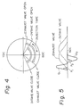
- Figure 4 illustrates an example of the opening time of the intake valves 6 and the exhaust valves 7 and an example of the injection time.
- the exhaust valves 7 open earlier than the intake valves 6, and the exhaust valves 7 close earlier than the intake valves 6.
- the fuel injection time is set to occur at a time after the intake valves 6 open and before the piston 2 reaches bottom dead center BDC.
- Figure 5 illutrates the valve lifts of the intake valves 6 and the exhaust valves 7 and illustrates changes in pressures P1 , P2 , Q1 , Q2 in the exhaust port 13.
- the changes in pressures P1 , P2 , Q1 , Q2 will be hereinafter described.
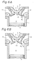
- Figure 6 illustrates a state where the engine is operating under a light load
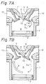
- Fig. 7 illustrates a case where the engine is operating under a heavy load
- Figs. 6(A) and 7(A) illustrate a moment immediately after the intake valves 6 open
- Figs. 6(b) and 7(B) illustrate a moment when the piston 2 is approximately at bottom dead center BDC.
- the fresh air does not reach the top face of the piston 2 but stays at the upper portion of the combustion chamber 4, and consequently, when the piston 2 moves upward, since the air-fuel mixture has collected at the upper portion of the combustion chamber 4, and the residual unburned gas has collected at the lower portion of the combustion chamber 4, the interior of the combustion chamber 4 is stratified, and thus the air-fuel mixture is properly ignited by the spark plug 8.
- the provision of the masking walls 10 makes it possible to prevent a flow of fresh air and fuel along the inner wall 3a of the cylinder head 3 which then flows out into the exhaust port 13, and as a result, a good scavenging operation and a good stratification can be obtained.
- the spark plug 8 on the intake valve side of the raised portion 5, the air-fuel mixture tends to collect around the spark plug 8, and thus it is possible to obtain a proper ignition of the air-fuel mixture by the spark plug 8. Particularly, the air-fuel mixture tends to stay within an area surrounded by the central arc portion 5c of the raised portion 5, and since the spark plug 8 is arranged in this area, the ignition is thus improved.
- the fuel injected from the fuel injectors 17 is instantaneously fed into the combustion chamber 4 after the fuel impinges upon the rear faces of the valve bodies of the intake valves 6, and is atomized, the fuel will not adhere to the inner walls of the intake ports 12.
- Figures 8 and 9 illustrate another embodiment of a two-stroke engine, by which an even better loop scavenging operation is obtained.
- a depression 20 is formed on the inner wall 3a of the cylinder head 3, and the intake valves 6 are arranged on the inner wall portion 3b of the cylinder head 3, which forms the bottom wall of the depression 20.
- the inner wall portion 3c of the cylinder head 3 other than the depression 20 is substantially flat, and the exhaust valves 7 are arranged on this inner wall portion 3c of the cylinder head 3.
- the inner wall portions 3b and 3c of the cylinder head 3 are interconnected via the peripheral wall 21 of the depression 20.
- the peripheral wall 21 of the depression 20 comprises masking walls 21a arranged as close as possible to the peripheral portions of the corresponding intake valves 6 and extending archwise along the periphery of the corresponding intake valves 6, a fresh air guide wall 21b arranged between the intake valves 6, and fresh air guide walls 21c each arranged between the circumferential wall of the inner wall 3a of the cylinder head 3 and the corresponding intake valve 6.
- the masking walls 21a extend toward the combustion chamber 4 to a position lower than the intake valves 6 when the valves 6 are in the maximum lift position, and thus the valve opening between the valve seat 9 and the peripheral portion of the intake valve 6, which is located on the exhaust valve side, is masked by the corresponding masking wall 21a for the entire time for which the intake valve 6 is open.
- the fresh air guide wall 21b and the fresh air guide walls 21c are located on substantially the same plane and extend substantially in parallel to the line passing through the centers of the intake valves 6.
- the spark plug 8 is arranged on the inner wall portion 3c of the cylinder head 3 in such a manner that it is located at the center of the inner wall 3a of the cylinder head 3.
- the arced masking walls 21a have a peripheral length longer than that of the masking wall 10 illustrated in Figs. 1 through 3, and thus, at the valve opening between the intake valve 6 and the valve seat 9, one-third of the valve opening, which is located on the exhaust valve side, is masked by the corresponding masking wall 21a, and the fresh air is fed from the unmasked two-thirds of the valve opening, which is located at the opposite side of the exhaust valve 7.
- the fresh air flowing into the combustion chamber 4 from the intake valve 6 is guided by the fresh air guide walls 21b, 21c so as to flow downward along the inner wall of the cylinder.
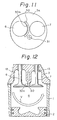
- Figures 11 and 12 illustrates the case where the present invention is applied to a two-stroke diesel engine.
- a downwardly extending projection 30 is formed on the inner wall 3a of the cylinder head 3 between the intake valve 6 and the exhaust valve 7, and a fuel injector 31 is arranged near the projection 30.
- This projection 30 is provided with a masking wall 30a arranged as close as possible to the peripheral portion of the intake valve 6 and extending in an arc along the periphery of the intake valve 6.
- the masking wall 30a extends downward toward the combustion chamber 4 to a position lower than the intake valve 6 when the valve 6 is in the maximum lift position, and thus the valve opening between the valve seat and the peripheral portion of the intake valve 6, which is located on the exhaust valve side, is masked by the masking wall 30a for the entire time for which the intake valve 6 is open. Consequently, also in this embodiment, air flows as illustrated by the arrow V in Fig. 12, and thus a good loop scavenging operation is carried out. Where a large projecting amount is necessary for the projection 30, it is possible to prevent the projection 30 from interfering with the piston 2 by arranging the projection 30 so that it faces the cavity of the piston 2.
- the masking wall is formed on the cylinder head, but the masking wall may be formed on a member which is separate from the cylinder head; for example, the masking wall may be formed on the valve seat for the intake valve or the exhaust valve by suitably modifying the shape of the valve seat.
- the present invention by masking the valve opening between the valve seat and the peripheral portion of the intake valve, which is located on the exhaust valve side, for the entire time for which the intake valve is open, by means of the masking wall, it is possible to obtain a good loop scavenging operation, and thus it is possible to obtain a good combustion and a high output power of the engine.
Landscapes
- Engineering & Computer Science (AREA)
- Chemical & Material Sciences (AREA)
- Combustion & Propulsion (AREA)
- Mechanical Engineering (AREA)
- General Engineering & Computer Science (AREA)
- Combustion Methods Of Internal-Combustion Engines (AREA)
Applications Claiming Priority (6)
| Application Number | Priority Date | Filing Date | Title |
|---|---|---|---|
| JP169684/87 | 1987-07-09 | ||
| JP16968487 | 1987-07-09 | ||
| JP28839087 | 1987-11-17 | ||
| JP288390/87 | 1987-11-17 | ||
| JP63102659A JPH0733770B2 (ja) | 1987-07-09 | 1988-04-27 | 2サイクル内燃機関の燃焼室構造 |
| JP102659/88 | 1988-04-27 |
Publications (3)
| Publication Number | Publication Date |
|---|---|
| EP0299385A2 true EP0299385A2 (de) | 1989-01-18 |
| EP0299385A3 EP0299385A3 (en) | 1990-03-28 |
| EP0299385B1 EP0299385B1 (de) | 1992-06-17 |
Family
ID=27309760
Family Applications (1)
| Application Number | Title | Priority Date | Filing Date |
|---|---|---|---|
| EP88110956A Expired EP0299385B1 (de) | 1987-07-09 | 1988-07-08 | Zweitaktmotor |
Country Status (6)
| Country | Link |
|---|---|
| US (1) | US4840147A (de) |
| EP (1) | EP0299385B1 (de) |
| JP (1) | JPH0733770B2 (de) |
| AU (1) | AU589321B2 (de) |
| CA (1) | CA1319576C (de) |
| DE (1) | DE3872074T2 (de) |
Cited By (16)
| Publication number | Priority date | Publication date | Assignee | Title |
|---|---|---|---|---|
| DE3913586A1 (de) * | 1988-04-26 | 1989-11-09 | Toyota Motor Co Ltd | Zweitakt-brennkraftmaschine |
| DE3928579A1 (de) * | 1988-08-30 | 1990-03-08 | Toyota Motor Co Ltd | Brennraum fuer eine brennkraftmaschine |
| EP0375789A4 (en) * | 1988-07-01 | 1990-12-12 | Toyota Jidosha Kabushiki Kaisha | Two-cycle internal combustion engine |
| EP0431866A1 (de) * | 1989-12-07 | 1991-06-12 | Ricardo Group Plc | Brennkraftmaschine |
| FR2658240A1 (fr) * | 1990-02-13 | 1991-08-16 | Melchior Technologie Snc | Perfectionnements aux moteurs a combustion interne a deux temps, a allumage par compression de type diesel. |
| EP0463613A1 (de) * | 1990-06-27 | 1992-01-02 | Toyota Jidosha Kabushiki Kaisha | Zweitaktbrennkraftmaschine |
| EP0464622A1 (de) * | 1990-06-27 | 1992-01-08 | Toyota Jidosha Kabushiki Kaisha | Zweitaktbrennkraftmaschine |
| EP0473992A1 (de) * | 1990-09-06 | 1992-03-11 | Toyota Jidosha Kabushiki Kaisha | Diesel-Zweitaktverbrennungsmotor |
| EP0532020A1 (de) * | 1991-09-13 | 1993-03-17 | Toyota Jidosha Kabushiki Kaisha | Brennkraftmaschine |
| EP0541080A1 (de) * | 1991-11-08 | 1993-05-12 | Toyota Jidosha Kabushiki Kaisha | Zweitaktbrennkraftmaschine |
| US5259348A (en) * | 1991-06-20 | 1993-11-09 | Toyota Jidosha Kabushiki Kaisha | Direct injection type engine |
| US5271362A (en) * | 1990-06-27 | 1993-12-21 | Toyota Jidosha Kabushiki Kaisha | Two-stroke engine |
| EP0959240A1 (de) * | 1998-05-22 | 1999-11-24 | Wärtsilä NSD Schweiz AG | Zylinderdeckel für eine Zweitakt-Dieselbrennkraftmaschine und einen solchen enthaltende Anordnung |
| DE3926631C2 (de) * | 1988-08-12 | 2000-05-04 | Toyota Motor Co Ltd | Zweitaktmotor |
| EP2000663A4 (de) * | 2006-03-29 | 2014-01-01 | Denso Corp | Installationsstruktur für ein kraftstoffeinspritzventil und kraftstoffeinspritzsystem |
| WO2014146579A1 (zh) * | 2013-03-19 | 2014-09-25 | Lio Pang-Chian | 具有气体分离装置的无压缩行程内燃机 |
Families Citing this family (16)
| Publication number | Priority date | Publication date | Assignee | Title |
|---|---|---|---|---|
| CH677004A5 (de) * | 1988-11-18 | 1991-03-28 | Nicholas J Johannes | |
| US5063886A (en) * | 1989-09-18 | 1991-11-12 | Toyota Jidosha Kabushiki Kaisha | Two-stroke engine |
| US4974566A (en) * | 1989-09-28 | 1990-12-04 | Ford Motor Company | Optimal swirl generation by valve control |
| JP2534032Y2 (ja) * | 1989-12-18 | 1997-04-30 | トヨタ自動車株式会社 | 予燃焼室付ディーゼル機関 |
| US4998513A (en) * | 1990-03-19 | 1991-03-12 | J-W Operating Company | 4-stroke, stratified gas engine |
| US5448971A (en) * | 1990-06-20 | 1995-09-12 | Group Lotus Limited | Internal combustion engine and an improved rotary inlet valve for use therewith |
| US5127379A (en) * | 1990-06-26 | 1992-07-07 | Toyota Jidosha Kabushiki Kaisha | Internal combustion engine |
| US5115774A (en) * | 1990-12-26 | 1992-05-26 | Toyota Jidosha Kabushiki Kaisha | Internal combustion engine |
| JPH04228850A (ja) * | 1990-12-27 | 1992-08-18 | Toyota Motor Corp | 筒内噴射式内燃機関 |
| JPH06185312A (ja) * | 1992-12-18 | 1994-07-05 | Toyota Motor Corp | 2サイクル機関の燃焼室 |
| US5870982A (en) * | 1997-11-12 | 1999-02-16 | Strawz; Frank T. | Intake valve of a supercharged two stroke engine |
| FR2886342B1 (fr) * | 2005-05-24 | 2010-08-27 | Inst Francais Du Petrole | Procede de controle du balayage des gaz brules d'un moteur a injection indirecte, notamment moteur suralimente, et moteur utilisant un tel procede |
| DE102012111776A1 (de) * | 2011-12-09 | 2013-06-13 | Ecomotors International, Inc. | Gegenkolbenmotor mit ringförmiger Brennkammer mit Seiteneinspritzung |
| CN103244303A (zh) * | 2012-02-04 | 2013-08-14 | D.恩德里戈 | 飞机发动机的汽缸盖 |
| US20130333656A1 (en) * | 2012-02-04 | 2013-12-19 | David Endrigo | Valve seats for cylinder heads in aircraft engines |
| EP3896267A1 (de) * | 2020-04-17 | 2021-10-20 | Winterthur Gas & Diesel AG | Längsgespülter grossmotor |
Family Cites Families (11)
| Publication number | Priority date | Publication date | Assignee | Title |
|---|---|---|---|---|
| JPS5624091B2 (de) * | 1973-05-04 | 1981-06-04 | ||
| FR2338385A1 (fr) * | 1976-01-15 | 1977-08-12 | Melchior Jean | Perfectionnements aux moteurs a combustion interne a deux temps |
| JPS5949407B2 (ja) * | 1976-11-15 | 1984-12-03 | トヨタ自動車株式会社 | 内燃機関の燃焼室 |
| JPS5728824A (en) * | 1980-07-26 | 1982-02-16 | Honda Motor Co Ltd | Combustion chamber device of engine |
| DE3143402A1 (de) * | 1981-11-02 | 1983-05-11 | Volkswagenwerk Ag, 3180 Wolfsburg | Zweitaktbrennkraftmaschine |
| DE3542965A1 (de) * | 1985-12-05 | 1987-06-11 | Ford Werke Ag | Gemischverdichtende brennkraftmaschine, insbesondere fremdgezuendete viertaktbrennkraftmaschine |
| FR2592430B1 (fr) * | 1985-12-31 | 1990-01-05 | Melchior Jean | Moteur a combustion interne a deux temps et culasse equipant celui-ci |
| JPH0663453B2 (ja) * | 1986-07-02 | 1994-08-22 | トヨタ自動車株式会社 | 2サイクル内燃機関 |
| US4732117A (en) * | 1986-07-02 | 1988-03-22 | Toyota Jidosha Kabushiki Kaisha | Two-cycle internal combustion engine |
| JPH0663452B2 (ja) * | 1986-07-04 | 1994-08-22 | トヨタ自動車株式会社 | 2サイクル内燃機関 |
| JPH086585B2 (ja) * | 1987-01-13 | 1996-01-24 | トヨタ自動車株式会社 | 2サイクル内燃機関 |
-
1988
- 1988-04-27 JP JP63102659A patent/JPH0733770B2/ja not_active Expired - Fee Related
- 1988-07-05 US US07/215,420 patent/US4840147A/en not_active Expired - Lifetime
- 1988-07-06 AU AU18758/88A patent/AU589321B2/en not_active Expired
- 1988-07-08 DE DE8888110956T patent/DE3872074T2/de not_active Expired - Lifetime
- 1988-07-08 EP EP88110956A patent/EP0299385B1/de not_active Expired
- 1988-07-08 CA CA000571596A patent/CA1319576C/en not_active Expired - Fee Related
Cited By (22)
| Publication number | Priority date | Publication date | Assignee | Title |
|---|---|---|---|---|
| DE3913586A1 (de) * | 1988-04-26 | 1989-11-09 | Toyota Motor Co Ltd | Zweitakt-brennkraftmaschine |
| EP0375789A4 (en) * | 1988-07-01 | 1990-12-12 | Toyota Jidosha Kabushiki Kaisha | Two-cycle internal combustion engine |
| US5062395A (en) * | 1988-07-01 | 1991-11-05 | Toyota Jidosha Kabushiki Kaisha | Two-stroke internal combustion engine |
| DE3926631C2 (de) * | 1988-08-12 | 2000-05-04 | Toyota Motor Co Ltd | Zweitaktmotor |
| DE3928579A1 (de) * | 1988-08-30 | 1990-03-08 | Toyota Motor Co Ltd | Brennraum fuer eine brennkraftmaschine |
| EP0431866A1 (de) * | 1989-12-07 | 1991-06-12 | Ricardo Group Plc | Brennkraftmaschine |
| FR2658240A1 (fr) * | 1990-02-13 | 1991-08-16 | Melchior Technologie Snc | Perfectionnements aux moteurs a combustion interne a deux temps, a allumage par compression de type diesel. |
| WO1991012419A1 (fr) * | 1990-02-13 | 1991-08-22 | S.N.C. Melchior Technologie | Perfectionnements aux moteurs a combustion interne a deux temps, a allumage par compression de type diesel |
| US5271362A (en) * | 1990-06-27 | 1993-12-21 | Toyota Jidosha Kabushiki Kaisha | Two-stroke engine |
| EP0464622A1 (de) * | 1990-06-27 | 1992-01-08 | Toyota Jidosha Kabushiki Kaisha | Zweitaktbrennkraftmaschine |
| US5140958A (en) * | 1990-06-27 | 1992-08-25 | Toyota Jidosha Kabushiki Kaisha | Two-stroke engine |
| EP0463613A1 (de) * | 1990-06-27 | 1992-01-02 | Toyota Jidosha Kabushiki Kaisha | Zweitaktbrennkraftmaschine |
| US5125380A (en) * | 1990-09-06 | 1992-06-30 | Toyota Jidosha Kabushiki Kaisha | Two-stroke diesel engine |
| EP0473992A1 (de) * | 1990-09-06 | 1992-03-11 | Toyota Jidosha Kabushiki Kaisha | Diesel-Zweitaktverbrennungsmotor |
| US5259348A (en) * | 1991-06-20 | 1993-11-09 | Toyota Jidosha Kabushiki Kaisha | Direct injection type engine |
| EP0532020A1 (de) * | 1991-09-13 | 1993-03-17 | Toyota Jidosha Kabushiki Kaisha | Brennkraftmaschine |
| US5291865A (en) * | 1991-09-13 | 1994-03-08 | Toyota Jidosha Kabushiki Kaisha | Internal combustion engine |
| US5357925A (en) * | 1991-09-13 | 1994-10-25 | Toyota Jidosha Kabushika Kaisha | Internal combustion engine |
| EP0541080A1 (de) * | 1991-11-08 | 1993-05-12 | Toyota Jidosha Kabushiki Kaisha | Zweitaktbrennkraftmaschine |
| EP0959240A1 (de) * | 1998-05-22 | 1999-11-24 | Wärtsilä NSD Schweiz AG | Zylinderdeckel für eine Zweitakt-Dieselbrennkraftmaschine und einen solchen enthaltende Anordnung |
| EP2000663A4 (de) * | 2006-03-29 | 2014-01-01 | Denso Corp | Installationsstruktur für ein kraftstoffeinspritzventil und kraftstoffeinspritzsystem |
| WO2014146579A1 (zh) * | 2013-03-19 | 2014-09-25 | Lio Pang-Chian | 具有气体分离装置的无压缩行程内燃机 |
Also Published As
| Publication number | Publication date |
|---|---|
| JPH02153222A (ja) | 1990-06-12 |
| DE3872074T2 (de) | 1992-12-03 |
| AU1875888A (en) | 1989-05-18 |
| US4840147A (en) | 1989-06-20 |
| CA1319576C (en) | 1993-06-29 |
| AU589321B2 (en) | 1989-10-05 |
| EP0299385A3 (en) | 1990-03-28 |
| DE3872074D1 (de) | 1992-07-23 |
| JPH0733770B2 (ja) | 1995-04-12 |
| EP0299385B1 (de) | 1992-06-17 |
Similar Documents
| Publication | Publication Date | Title |
|---|---|---|
| EP0299385B1 (de) | Zweitaktmotor | |
| US4957081A (en) | Combustion chamber of an engine | |
| US5115774A (en) | Internal combustion engine | |
| US5115776A (en) | Internal combustion engine | |
| JPS63173813A (ja) | 2サイクル内燃機関 | |
| US4732116A (en) | Two-cycle internal combustion engine | |
| US4883030A (en) | Combustion chamber of a two-stroke engine | |
| US4271810A (en) | Divided chamber engine with prechamber exhaust recirculation | |
| US4938213A (en) | Two-stroke engine | |
| US4945867A (en) | Two-stroke engine | |
| US4237826A (en) | Multi-cylinder internal combustion engine equipped with an accumulation chamber | |
| US4178903A (en) | Internal combustion engine with an auxiliary combustion chamber | |
| US5343839A (en) | Two-stroke engine | |
| US4367707A (en) | Combustion chamber of an internal combustion engine | |
| US4162663A (en) | Stratified charge four-stroke engine | |
| US4230073A (en) | Combustion chamber of an internal combustion engine | |
| EP0541080B1 (de) | Zweitaktbrennkraftmaschine | |
| US3967611A (en) | Stratified-combustion type internal combustion engine with pre-combustion-chamber | |
| US6401702B1 (en) | Controlled two-stroke internal combustion engine | |
| JPH0545789Y2 (de) | ||
| US5934262A (en) | Combustion chamber for internal combustion engine | |
| JPH05280344A (ja) | 2サイクル内燃機関 | |
| JPH0299719A (ja) | 2サイクル内燃機関の燃焼室構造 | |
| JPH0733771B2 (ja) | 2サイクル内燃機関 | |
| JPH0341055Y2 (de) |
Legal Events
| Date | Code | Title | Description |
|---|---|---|---|
| PUAI | Public reference made under article 153(3) epc to a published international application that has entered the european phase |
Free format text: ORIGINAL CODE: 0009012 |
|
| 17P | Request for examination filed |
Effective date: 19880708 |
|
| AK | Designated contracting states |
Kind code of ref document: A2 Designated state(s): DE FR GB IT SE |
|
| PUAL | Search report despatched |
Free format text: ORIGINAL CODE: 0009013 |
|
| AK | Designated contracting states |
Kind code of ref document: A3 Designated state(s): DE FR GB IT SE |
|
| 17Q | First examination report despatched |
Effective date: 19910213 |
|
| GRAA | (expected) grant |
Free format text: ORIGINAL CODE: 0009210 |
|
| AK | Designated contracting states |
Kind code of ref document: B1 Designated state(s): DE FR GB IT SE |
|
| REF | Corresponds to: |
Ref document number: 3872074 Country of ref document: DE Date of ref document: 19920723 |
|
| ET | Fr: translation filed | ||
| ITF | It: translation for a ep patent filed | ||
| PLBE | No opposition filed within time limit |
Free format text: ORIGINAL CODE: 0009261 |
|
| STAA | Information on the status of an ep patent application or granted ep patent |
Free format text: STATUS: NO OPPOSITION FILED WITHIN TIME LIMIT |
|
| 26N | No opposition filed | ||
| EAL | Se: european patent in force in sweden |
Ref document number: 88110956.5 |
|
| REG | Reference to a national code |
Ref country code: GB Ref legal event code: 746 Effective date: 19991109 |
|
| REG | Reference to a national code |
Ref country code: FR Ref legal event code: D6 |
|
| REG | Reference to a national code |
Ref country code: GB Ref legal event code: IF02 |
|
| PGFP | Annual fee paid to national office [announced via postgrant information from national office to epo] |
Ref country code: DE Payment date: 20070705 Year of fee payment: 20 |
|
| PGFP | Annual fee paid to national office [announced via postgrant information from national office to epo] |
Ref country code: GB Payment date: 20070704 Year of fee payment: 20 |
|
| PGFP | Annual fee paid to national office [announced via postgrant information from national office to epo] |
Ref country code: IT Payment date: 20070727 Year of fee payment: 20 Ref country code: SE Payment date: 20070704 Year of fee payment: 20 |
|
| PGFP | Annual fee paid to national office [announced via postgrant information from national office to epo] |
Ref country code: FR Payment date: 20070710 Year of fee payment: 20 |
|
| REG | Reference to a national code |
Ref country code: GB Ref legal event code: PE20 Expiry date: 20080707 |
|
| EUG | Se: european patent has lapsed | ||
| PG25 | Lapsed in a contracting state [announced via postgrant information from national office to epo] |
Ref country code: GB Free format text: LAPSE BECAUSE OF EXPIRATION OF PROTECTION Effective date: 20080707 |