EP0299738A2 - Dispositif de mesure de tension - Google Patents
Dispositif de mesure de tension Download PDFInfo
- Publication number
- EP0299738A2 EP0299738A2 EP88306411A EP88306411A EP0299738A2 EP 0299738 A2 EP0299738 A2 EP 0299738A2 EP 88306411 A EP88306411 A EP 88306411A EP 88306411 A EP88306411 A EP 88306411A EP 0299738 A2 EP0299738 A2 EP 0299738A2
- Authority
- EP
- European Patent Office
- Prior art keywords
- beams
- guide
- threadline
- tension
- thickness
- Prior art date
- Legal status (The legal status is an assumption and is not a legal conclusion. Google has not performed a legal analysis and makes no representation as to the accuracy of the status listed.)
- Granted
Links
- 230000003247 decreasing effect Effects 0.000 claims description 3
- 230000009977 dual effect Effects 0.000 abstract description 2
- 238000005259 measurement Methods 0.000 description 4
- 238000012545 processing Methods 0.000 description 4
- 230000035945 sensitivity Effects 0.000 description 4
- 230000006835 compression Effects 0.000 description 2
- 238000007906 compression Methods 0.000 description 2
- 230000005284 excitation Effects 0.000 description 2
- 238000000034 method Methods 0.000 description 2
- 230000001681 protective effect Effects 0.000 description 2
- 229910000838 Al alloy Inorganic materials 0.000 description 1
- 238000010276 construction Methods 0.000 description 1
- 238000013461 design Methods 0.000 description 1
- 238000010586 diagram Methods 0.000 description 1
- 238000009429 electrical wiring Methods 0.000 description 1
- 239000012530 fluid Substances 0.000 description 1
- 239000000463 material Substances 0.000 description 1
- 238000012806 monitoring device Methods 0.000 description 1
- 238000012544 monitoring process Methods 0.000 description 1
Images


Classifications
-
- G—PHYSICS
- G01—MEASURING; TESTING
- G01L—MEASURING FORCE, STRESS, TORQUE, WORK, MECHANICAL POWER, MECHANICAL EFFICIENCY, OR FLUID PRESSURE
- G01L5/00—Apparatus for, or methods of, measuring force, work, mechanical power, or torque, specially adapted for specific purposes
- G01L5/04—Apparatus for, or methods of, measuring force, work, mechanical power, or torque, specially adapted for specific purposes for measuring tension in flexible members, e.g. ropes, cables, wires, threads, belts or bands
- G01L5/10—Apparatus for, or methods of, measuring force, work, mechanical power, or torque, specially adapted for specific purposes for measuring tension in flexible members, e.g. ropes, cables, wires, threads, belts or bands using electrical means
- G01L5/106—Apparatus for, or methods of, measuring force, work, mechanical power, or torque, specially adapted for specific purposes for measuring tension in flexible members, e.g. ropes, cables, wires, threads, belts or bands using electrical means for measuring a reaction force applied on a cantilever beam
-
- B—PERFORMING OPERATIONS; TRANSPORTING
- B65—CONVEYING; PACKING; STORING; HANDLING THIN OR FILAMENTARY MATERIAL
- B65H—HANDLING THIN OR FILAMENTARY MATERIAL, e.g. SHEETS, WEBS, CABLES
- B65H59/00—Adjusting or controlling tension in filamentary material, e.g. for preventing snarling; Applications of tension indicators
- B65H59/40—Applications of tension indicators
-
- G—PHYSICS
- G01—MEASURING; TESTING
- G01L—MEASURING FORCE, STRESS, TORQUE, WORK, MECHANICAL POWER, MECHANICAL EFFICIENCY, OR FLUID PRESSURE
- G01L5/00—Apparatus for, or methods of, measuring force, work, mechanical power, or torque, specially adapted for specific purposes
- G01L5/04—Apparatus for, or methods of, measuring force, work, mechanical power, or torque, specially adapted for specific purposes for measuring tension in flexible members, e.g. ropes, cables, wires, threads, belts or bands
- G01L5/10—Apparatus for, or methods of, measuring force, work, mechanical power, or torque, specially adapted for specific purposes for measuring tension in flexible members, e.g. ropes, cables, wires, threads, belts or bands using electrical means
-
- G—PHYSICS
- G01—MEASURING; TESTING
- G01L—MEASURING FORCE, STRESS, TORQUE, WORK, MECHANICAL POWER, MECHANICAL EFFICIENCY, OR FLUID PRESSURE
- G01L5/00—Apparatus for, or methods of, measuring force, work, mechanical power, or torque, specially adapted for specific purposes
- G01L5/04—Apparatus for, or methods of, measuring force, work, mechanical power, or torque, specially adapted for specific purposes for measuring tension in flexible members, e.g. ropes, cables, wires, threads, belts or bands
- G01L5/10—Apparatus for, or methods of, measuring force, work, mechanical power, or torque, specially adapted for specific purposes for measuring tension in flexible members, e.g. ropes, cables, wires, threads, belts or bands using electrical means
- G01L5/108—Apparatus for, or methods of, measuring force, work, mechanical power, or torque, specially adapted for specific purposes for measuring tension in flexible members, e.g. ropes, cables, wires, threads, belts or bands using electrical means for measuring a reaction force applied on a single support, e.g. a glider
-
- B—PERFORMING OPERATIONS; TRANSPORTING
- B65—CONVEYING; PACKING; STORING; HANDLING THIN OR FILAMENTARY MATERIAL
- B65H—HANDLING THIN OR FILAMENTARY MATERIAL, e.g. SHEETS, WEBS, CABLES
- B65H2701/00—Handled material; Storage means
- B65H2701/30—Handled filamentary material
- B65H2701/31—Textiles threads or artificial strands of filaments
Definitions
- This invention relates to measurement of tension in a moving threadline, and more particularly, to a tensiometer having an even surface threadline guide.
- U.S. Patent 4,295,360 to Fountain discloses one device for measuring threadline tension that includes a threadline direction-changing guide mounted at one end of a strain sensing cantilever.
- the threadline guide is typical of other prior art tensiometer guides in that it includes a groove for containing and preventing the threadline from wandering longitudinally along the guide surface.
- U.S. Patent Re 31,312 to Eddens discloses a tension monitoring device having a rotatable pully with an annular groove for accepting strand material.
- the use of a grooved guide surface for containing a moving threadline has been found to be undesirable for several reasons.
- This invention provides a threadline tension measuring apparatus which has a non-grooved even threadline guide surface, wherein measured tension is insensitive to the axial location of the threadline.
- the apparatus has a pair of deflectable beams spaced from the parallel to each other, said beams are attached at one end to an even surfaced thread guide and fixed at the opposite end to a base.
- the beams have successive lengths of varying thickness from each end. The lengths of varying thickness decrease to a minimum thickness then increase to a maximum thickness from each end and there are two strain transducers mounted at each end of each beam at the locations of minimum thickness.
- the invention provides a dual beam tension measuring device of a one-piece integral design having maximum sensitivity to flexure in a plane normal to said beams while maintaining structural stability against forces perpendicular or rotational to said beams.
- the tension measuring device further includes a cover for protection from hostile threadline processing environments and overload protection.
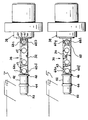
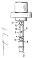
- Figs. 1 and 2 show an assembled tensiometer 10 of this invention wherein a threadline 12 passes through an opening 14 in protective cover 16 to engage an even surface threadline guide 18.
- Protective cover 16 is a hollow cylindrical body which is adjustably mounted to overload support flange 16a by passing threaded bolts 20 through arcuate slots 22 of cover flange 16b and into threaded holes 24 of flange 16a. Cover 16 can be adjusted by rotating it about its longitudinal axis until the desired orientation of opening 14 is achieved. Cover 16 has drain holes 26 located on the underside thereof for the release of any threadline processing fluids which might accumulate within the tensiometer during actual operation. Cover 16 acts to protect the threadline guide 18 from damage caused by accidental contact of the tensiometer with process tools or misaligned threadlines during threadline processing operations.
- tension measuring beam block 30 is now described.
- Two rectangular deflectable beams 32 and 34 are positioned parallel to and separated from each other to define a space 36. Beams 32 and 34 are fixed at one end to end member 38 and at the opposite end to front member 40.
- Front member 40 has fixed thereto a threadline guide mounting means comprising a cylindrical shaft 42 extending out from front member 40, a collar 44 attached to shaft 42 and attachment member 52, extending from shaft 42 and having a threaded opening 54 defined therein.
- Each beam 32,34 has a width (W) greater than its thickness (t) and the width of the beams is oriented to detect forces perpendicular thereto.
- An important feature of each beam is the manner in which its thickness varies along its length. More particularly, each beam has successive lengths of varying thickness from each end. These lengths will be described in detail for beam 32 only since beams 32 and 34 are structured the same.
- beam 32 From the end fixed to end member 38, there are successive lengths 33,37, decreasing from a maximum to a minimum thickness at location 35 then increasing to the maximum thickness, respectively. From the end of beam 32 attached to front member 40 the beam has successive lengths 39,43 decreasing from a maximum to a minimum thickness at location 41 then back to the maximum thickness, respectively.
- Beam block 30 is preferably of one-piece construction and machined from 2024-351 aluminum alloy.
- Lower beam 34 Fixed to the outer (i.e. upper) surface of the beam 32 are four strain gage members 60a, 60b, 60c, and 60d located at both ends of and off center of the longitudinal axes at the location of minimum thickness of said beam.
- Lower beam 34 has four strain gages, 60e, 60f, 60g, 60h attached to its outer (i.e., lower) surface in identical fashion to upper beam 32.
- Beams 32, 34 have locations of minimum thickness as described above that represent maximum flexure points for the beams and strain gage members 60 a - h are advantageously located on beams at these locations. This allows for maximum sensitivity to flexure in a plane normal to beams 32,34 while the rectangular beam configuration maintains structural stability against forces perpendicular to said beams. Fixing of the beams 32,34 both to members 38 and 40 aids in maintaining structural stability against forces rotational to the beam axis.
- Beams 32,34 are further defined by having a plurality of openings 43 centered on the plane of the beam. Openings 43 allow for a reduction in mass of the beam members while maintaining stability against off-axis loading of the beams as well as allowing for improved stress versus load on the attached strain gages 60. Beam length is advantageously several times longer than beam width.
- Hollow cylindrical overload protection member 75 is positioned over beam block 30, centered by the hub 38 a of member 38 with its flange 15 secured to the mounting flange 16 a of overload member 75 by bolt 11.
- Threadline guide 18 is secured to beam block member 52 by passing threaded bolt 52a through washer 52b and into threaded opening 54.
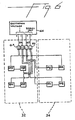
- strain gages 60 a - 60 h are interconnected to form a bridge circuit which in turn is connected to a strain gage input amplifier 62.
- the amplifier 62 (Model 3B16-00 by Analog Devices Co. Boston, Ma.) supplies excitation voltage to the bridge and receives voltage signals from the bridge and amplifies them for a measured output proportional to tension. More particularly, a DC voltage for excitation of the bridge circuit is supplied by amplifier 62 to terminal tabs 63,64 on the end of beam 32 and voltage signals from the bridge are fed to amplifier 62 via terminals 65,66 also on beam 32.
- threadline 12 runs over guide 18 which causes attached beams 32,34 to flex in proportion to threadline tension thereby putting strain gages 60a, 60b, 60e, 60f in tension and gages 60g, 60h, 60c 60d in compression.
- the tension and compression of the gages result in a voltage signal output from the bridge circuit proportional to the flexure of the beams and therefore threadline tension. Measured tension will be independent of the axial location of the threadline on the surface of guide 18.
- Tensiometers built as described above will accurately measure threadline tensions in the 10-10000 gram range.
Landscapes
- Physics & Mathematics (AREA)
- General Physics & Mathematics (AREA)
- Force Measurement Appropriate To Specific Purposes (AREA)
Applications Claiming Priority (2)
| Application Number | Priority Date | Filing Date | Title |
|---|---|---|---|
| US07/073,098 US4821583A (en) | 1987-07-14 | 1987-07-14 | Tension measuring apparatus |
| US73098 | 1987-07-14 |
Publications (3)
| Publication Number | Publication Date |
|---|---|
| EP0299738A2 true EP0299738A2 (fr) | 1989-01-18 |
| EP0299738A3 EP0299738A3 (en) | 1989-08-30 |
| EP0299738B1 EP0299738B1 (fr) | 1992-06-17 |
Family
ID=22111717
Family Applications (1)
| Application Number | Title | Priority Date | Filing Date |
|---|---|---|---|
| EP88306411A Expired - Lifetime EP0299738B1 (fr) | 1987-07-14 | 1988-07-13 | Dispositif de mesure de tension |
Country Status (5)
| Country | Link |
|---|---|
| US (1) | US4821583A (fr) |
| EP (1) | EP0299738B1 (fr) |
| JP (1) | JPS6432139A (fr) |
| CA (1) | CA1310514C (fr) |
| DE (1) | DE3872077T2 (fr) |
Cited By (5)
| Publication number | Priority date | Publication date | Assignee | Title |
|---|---|---|---|---|
| DE4030892A1 (de) * | 1990-09-29 | 1992-04-02 | Schlafhorst & Co W | Spuleinrichtung an einer textilmaschine |
| EP0388879A3 (fr) * | 1989-03-20 | 1992-05-20 | E.I. Du Pont De Nemours And Company | Extensomètre hermétique |
| DE4204231A1 (de) * | 1992-02-13 | 1993-08-19 | Honigmann Ind Elektronik Gmbh | Zugkraftmesseinrichtung |
| WO2004099746A1 (fr) * | 2003-05-07 | 2004-11-18 | Robert Bosch Gmbh | Element dynamometrique |
| US10343058B2 (en) | 2007-10-09 | 2019-07-09 | Nintendo Co., Ltd. | Storage medium storing a load detecting program and load detecting apparatus |
Families Citing this family (18)
| Publication number | Priority date | Publication date | Assignee | Title |
|---|---|---|---|---|
| JP3725252B2 (ja) * | 1996-08-01 | 2005-12-07 | 松下電器産業株式会社 | 荷重センサ |
| US7021159B2 (en) * | 2002-09-30 | 2006-04-04 | The Gates Corporation | Transducer |
| US20040244504A1 (en) * | 2003-06-04 | 2004-12-09 | Jing Yuan | Apparatus and method of belt dynamic tension measurement |
| USD531533S1 (en) * | 2004-07-28 | 2006-11-07 | Sartorius Hamburg Gmbh | Load cell for a scale |
| EP1923684B1 (fr) * | 2006-11-20 | 2011-02-16 | Texmag GmbH Vertriebsgesellschaft | Dispositif destiné à la mesure d'une force de traction à l'intérieur d'une nappe de tissu ou d'un écheveau de fil |
| JP5427343B2 (ja) | 2007-04-20 | 2014-02-26 | 任天堂株式会社 | ゲームコントローラ |
| JP2009047526A (ja) * | 2007-08-20 | 2009-03-05 | Murata Mach Ltd | テンションセンサ |
| DE102007044225A1 (de) * | 2007-09-17 | 2009-03-19 | Liebherr-Werk Nenzing Gmbh, Nenzing | Vorrichtung zum Messen mechanischer Größen, Verfahren zum Messen mechanischer Größen sowie Verwendung einer Vorrichtung zum Messen mechanischer Größen |
| JP5427346B2 (ja) | 2007-10-05 | 2014-02-26 | 任天堂株式会社 | 荷重検出プログラム、荷重検出装置、荷重検出システムおよび荷重検出方法 |
| JP4382844B2 (ja) | 2007-10-31 | 2009-12-16 | 任天堂株式会社 | 調整用加重機、および調整用加重方法 |
| JP5361349B2 (ja) | 2008-11-28 | 2013-12-04 | 任天堂株式会社 | 情報処理装置、コンピュータプログラム、情報処理システム、および情報処理方法 |
| JP5806443B2 (ja) | 2008-12-26 | 2015-11-10 | 任天堂株式会社 | 生体情報管理システム |
| JP5271121B2 (ja) | 2009-03-09 | 2013-08-21 | 任天堂株式会社 | 情報処理プログラム、情報処理装置、情報処理システム、および情報処理方法 |
| JP5436909B2 (ja) | 2009-03-30 | 2014-03-05 | 任天堂株式会社 | 情報処理プログラム、情報処理装置、情報処理システム、および、情報処理方法 |
| JP5161182B2 (ja) | 2009-09-28 | 2013-03-13 | 任天堂株式会社 | 情報処理プログラム及び情報処理装置 |
| JP5610735B2 (ja) | 2009-09-29 | 2014-10-22 | 任天堂株式会社 | 情報処理プログラム、情報処理装置、情報処理方法、および、情報処理システム |
| JP5496591B2 (ja) | 2009-09-30 | 2014-05-21 | 任天堂株式会社 | 情報処理プログラム及び情報処理装置 |
| US20220002107A1 (en) * | 2020-07-01 | 2022-01-06 | CSG Holding, Inc. | Webtension transducer load cell with integrated data interface |
Family Cites Families (18)
| Publication number | Priority date | Publication date | Assignee | Title |
|---|---|---|---|---|
| US2911823A (en) * | 1954-11-02 | 1959-11-10 | Celanese Corp | Tensiometer |
| CH353555A (de) * | 1956-04-06 | 1961-04-15 | Baldwin Lima Hamilton Corp | Kraftmesseinrichtung |
| US3280623A (en) * | 1964-04-10 | 1966-10-25 | Erwin J Saxl | Load cell for measurement of low forces |
| US3512406A (en) * | 1966-09-12 | 1970-05-19 | Geoffrey Roberts | Tension meter |
| SE311573B (fr) * | 1967-02-08 | 1969-06-16 | Bofors Ab | |
| US3602866A (en) * | 1968-12-18 | 1971-08-31 | Erwin J Saxl | Force transducer |
| US3739633A (en) * | 1971-09-15 | 1973-06-19 | E Saxl | Apparatus for measuring tension in web-type materials |
| USRE31312E (en) * | 1977-10-11 | 1983-07-19 | W. J. Industries, Inc. | Tension monitor means |
| JPS6023065B2 (ja) * | 1978-02-16 | 1985-06-05 | 東レ株式会社 | 糸条巻取装置 |
| US4326424A (en) * | 1979-03-30 | 1982-04-27 | Cleveland Machine Controls, Inc. | Web tension transducer arrangement |
| US4295360A (en) * | 1980-01-14 | 1981-10-20 | E. I. Du Pont De Nemours And Company | Tension measuring apparatus |
| JPS58142206A (ja) * | 1982-02-18 | 1983-08-24 | Tokyo Electric Co Ltd | 歪センサ |
| AU547838B2 (en) * | 1982-10-26 | 1985-11-07 | Ishida Koki Seisakusho K.K. | Load cell |
| JPS6151532A (ja) * | 1984-08-21 | 1986-03-14 | Tokyo Electric Co Ltd | ロ−ドセル |
| US4674339A (en) * | 1984-08-30 | 1987-06-23 | Yotaro Hatamura | Multi-axis load sensor |
| CN1014830B (zh) * | 1985-02-27 | 1991-11-20 | 巴马格·巴默机器制造股份公司 | 带有可作弹性运动的纤维探测器的纤维拉力测量装置 |
| FR2580073B1 (fr) * | 1985-04-09 | 1987-06-05 | Electro Resistance | |
| US4674341A (en) * | 1986-03-07 | 1987-06-23 | Cleveland Machine Controls, Inc. | Web tension transducer apparatus |
-
1987
- 1987-07-14 US US07/073,098 patent/US4821583A/en not_active Expired - Fee Related
-
1988
- 1988-07-11 JP JP63171090A patent/JPS6432139A/ja active Pending
- 1988-07-13 EP EP88306411A patent/EP0299738B1/fr not_active Expired - Lifetime
- 1988-07-13 DE DE8888306411T patent/DE3872077T2/de not_active Expired - Lifetime
- 1988-07-14 CA CA000572053A patent/CA1310514C/fr not_active Expired - Lifetime
Cited By (7)
| Publication number | Priority date | Publication date | Assignee | Title |
|---|---|---|---|---|
| EP0388879A3 (fr) * | 1989-03-20 | 1992-05-20 | E.I. Du Pont De Nemours And Company | Extensomètre hermétique |
| DE4030892A1 (de) * | 1990-09-29 | 1992-04-02 | Schlafhorst & Co W | Spuleinrichtung an einer textilmaschine |
| DE4030892C2 (de) * | 1990-09-29 | 2000-06-29 | Schlafhorst & Co W | Spuleinrichtung an einer Textilmaschine |
| DE4204231A1 (de) * | 1992-02-13 | 1993-08-19 | Honigmann Ind Elektronik Gmbh | Zugkraftmesseinrichtung |
| WO2004099746A1 (fr) * | 2003-05-07 | 2004-11-18 | Robert Bosch Gmbh | Element dynamometrique |
| US7437943B2 (en) | 2003-05-07 | 2008-10-21 | Robert Bosch Gmbh | Force measurement element |
| US10343058B2 (en) | 2007-10-09 | 2019-07-09 | Nintendo Co., Ltd. | Storage medium storing a load detecting program and load detecting apparatus |
Also Published As
| Publication number | Publication date |
|---|---|
| CA1310514C (fr) | 1992-11-24 |
| DE3872077T2 (de) | 1992-12-03 |
| EP0299738A3 (en) | 1989-08-30 |
| US4821583A (en) | 1989-04-18 |
| JPS6432139A (en) | 1989-02-02 |
| EP0299738B1 (fr) | 1992-06-17 |
| DE3872077D1 (de) | 1992-07-23 |
Similar Documents
| Publication | Publication Date | Title |
|---|---|---|
| EP0299738B1 (fr) | Dispositif de mesure de tension | |
| US4281539A (en) | Measuring apparatus, especially for measuring forces acting upon a bearing or the like | |
| US4454770A (en) | Torque-insensitive load cell | |
| US3439761A (en) | Strain-gage transducer structures | |
| US5317916A (en) | Digit grip sensor | |
| USRE31312E (en) | Tension monitor means | |
| US4548085A (en) | Tension measuring device and method for flexible linear material | |
| US3327270A (en) | Semi-conductor sensing assembly | |
| US5275062A (en) | Web tension measuring device for use with web coiling equipment | |
| EP3418234B1 (fr) | Ensemble de terminaison d'ascenseur qui fournit une indication de charge de cabine d'ascenseur | |
| US3411348A (en) | Electronic dynamometer | |
| US3279550A (en) | Truck load measuring system | |
| US12117359B2 (en) | Multi-dimensional sheave for use in tension measurement systems | |
| US4771640A (en) | Load introducing device | |
| US4120197A (en) | Device for sensing exerted load on a rope, wire, or the like | |
| US4514905A (en) | Convergence extensometer for measuring mine roof subsidence | |
| JP3320054B2 (ja) | 把持力変換器 | |
| US3381527A (en) | Tension measurement device | |
| US4597460A (en) | Multiple load cell weighing structure | |
| SE505738C2 (sv) | Anordning och förfarande för tvåaxlig kraftmätning jämte förfarande för bestämning av den varierande brytvinkeln respektive en dragkraft hos en löpande materialbana med hjälp av en anordning för tvåaxlig kraftmätning | |
| USRE32003E (en) | Constant moment weigh scale with floating flexure beam | |
| US5560118A (en) | Linear position transducer | |
| US3354711A (en) | Continuous thread tension indicating drive roller | |
| US6151957A (en) | Measuring device comprising an excitable frequency gauge | |
| US4912983A (en) | Sealed tensiometer |
Legal Events
| Date | Code | Title | Description |
|---|---|---|---|
| PUAI | Public reference made under article 153(3) epc to a published international application that has entered the european phase |
Free format text: ORIGINAL CODE: 0009012 |
|
| AK | Designated contracting states |
Kind code of ref document: A2 Designated state(s): DE GB |
|
| PUAL | Search report despatched |
Free format text: ORIGINAL CODE: 0009013 |
|
| AK | Designated contracting states |
Kind code of ref document: A3 Designated state(s): DE GB |
|
| 17P | Request for examination filed |
Effective date: 19900205 |
|
| 17Q | First examination report despatched |
Effective date: 19910405 |
|
| GRAA | (expected) grant |
Free format text: ORIGINAL CODE: 0009210 |
|
| AK | Designated contracting states |
Kind code of ref document: B1 Designated state(s): DE GB |
|
| REF | Corresponds to: |
Ref document number: 3872077 Country of ref document: DE Date of ref document: 19920723 |
|
| PLBE | No opposition filed within time limit |
Free format text: ORIGINAL CODE: 0009261 |
|
| STAA | Information on the status of an ep patent application or granted ep patent |
Free format text: STATUS: NO OPPOSITION FILED WITHIN TIME LIMIT |
|
| 26N | No opposition filed | ||
| PGFP | Annual fee paid to national office [announced via postgrant information from national office to epo] |
Ref country code: DE Payment date: 19950606 Year of fee payment: 8 |
|
| PGFP | Annual fee paid to national office [announced via postgrant information from national office to epo] |
Ref country code: GB Payment date: 19950621 Year of fee payment: 8 |
|
| PG25 | Lapsed in a contracting state [announced via postgrant information from national office to epo] |
Ref country code: GB Effective date: 19960713 |
|
| GBPC | Gb: european patent ceased through non-payment of renewal fee |
Effective date: 19960713 |
|
| PG25 | Lapsed in a contracting state [announced via postgrant information from national office to epo] |
Ref country code: DE Effective date: 19970402 |