EP0300090A2 - Ressort du type à manchon en caoutchouc - Google Patents
Ressort du type à manchon en caoutchouc Download PDFInfo
- Publication number
- EP0300090A2 EP0300090A2 EP87116640A EP87116640A EP0300090A2 EP 0300090 A2 EP0300090 A2 EP 0300090A2 EP 87116640 A EP87116640 A EP 87116640A EP 87116640 A EP87116640 A EP 87116640A EP 0300090 A2 EP0300090 A2 EP 0300090A2
- Authority
- EP
- European Patent Office
- Prior art keywords
- webs
- rubber spring
- sleeve
- sleeve rubber
- spring according
- Prior art date
- Legal status (The legal status is an assumption and is not a legal conclusion. Google has not performed a legal analysis and makes no representation as to the accuracy of the status listed.)
- Withdrawn
Links
- 238000004519 manufacturing process Methods 0.000 claims abstract description 18
- 239000007788 liquid Substances 0.000 claims abstract description 15
- 230000006835 compression Effects 0.000 claims description 22
- 238000007906 compression Methods 0.000 claims description 22
- 230000036961 partial effect Effects 0.000 claims description 22
- 230000003068 static effect Effects 0.000 claims description 10
- 239000002184 metal Substances 0.000 claims description 6
- 230000004323 axial length Effects 0.000 claims description 4
- 238000009434 installation Methods 0.000 abstract description 2
- 238000005192 partition Methods 0.000 abstract 1
- 238000003780 insertion Methods 0.000 description 10
- 230000037431 insertion Effects 0.000 description 10
- 230000036316 preload Effects 0.000 description 10
- 238000013461 design Methods 0.000 description 9
- 230000000875 corresponding effect Effects 0.000 description 8
- 238000013016 damping Methods 0.000 description 8
- 230000000694 effects Effects 0.000 description 8
- 238000006073 displacement reaction Methods 0.000 description 7
- 238000004073 vulcanization Methods 0.000 description 7
- 238000000034 method Methods 0.000 description 6
- 238000005304 joining Methods 0.000 description 4
- 238000007789 sealing Methods 0.000 description 4
- 238000002955 isolation Methods 0.000 description 3
- 239000000725 suspension Substances 0.000 description 3
- LYCAIKOWRPUZTN-UHFFFAOYSA-N Ethylene glycol Chemical compound OCCO LYCAIKOWRPUZTN-UHFFFAOYSA-N 0.000 description 2
- 239000011248 coating agent Substances 0.000 description 2
- 238000000576 coating method Methods 0.000 description 2
- 238000001816 cooling Methods 0.000 description 2
- 230000007797 corrosion Effects 0.000 description 2
- 238000005260 corrosion Methods 0.000 description 2
- 230000006378 damage Effects 0.000 description 2
- 238000003825 pressing Methods 0.000 description 2
- 238000012546 transfer Methods 0.000 description 2
- 230000002411 adverse Effects 0.000 description 1
- 238000007596 consolidation process Methods 0.000 description 1
- WGCNASOHLSPBMP-UHFFFAOYSA-N hydroxyacetaldehyde Natural products OCC=O WGCNASOHLSPBMP-UHFFFAOYSA-N 0.000 description 1
- 230000000670 limiting effect Effects 0.000 description 1
- 239000012528 membrane Substances 0.000 description 1
- 239000000203 mixture Substances 0.000 description 1
- 230000008092 positive effect Effects 0.000 description 1
- 230000002829 reductive effect Effects 0.000 description 1
- 238000004904 shortening Methods 0.000 description 1
- 238000012360 testing method Methods 0.000 description 1
- 238000012549 training Methods 0.000 description 1
- 230000007704 transition Effects 0.000 description 1
- XLYOFNOQVPJJNP-UHFFFAOYSA-N water Substances O XLYOFNOQVPJJNP-UHFFFAOYSA-N 0.000 description 1
Images





Classifications
-
- F—MECHANICAL ENGINEERING; LIGHTING; HEATING; WEAPONS; BLASTING
- F16—ENGINEERING ELEMENTS AND UNITS; GENERAL MEASURES FOR PRODUCING AND MAINTAINING EFFECTIVE FUNCTIONING OF MACHINES OR INSTALLATIONS; THERMAL INSULATION IN GENERAL
- F16F—SPRINGS; SHOCK-ABSORBERS; MEANS FOR DAMPING VIBRATION
- F16F13/00—Units comprising springs of the non-fluid type as well as vibration-dampers, shock-absorbers, or fluid springs
- F16F13/04—Units comprising springs of the non-fluid type as well as vibration-dampers, shock-absorbers, or fluid springs comprising both a plastics spring and a damper, e.g. a friction damper
- F16F13/06—Units comprising springs of the non-fluid type as well as vibration-dampers, shock-absorbers, or fluid springs comprising both a plastics spring and a damper, e.g. a friction damper the damper being a fluid damper, e.g. the plastics spring not forming a part of the wall of the fluid chamber of the damper
- F16F13/08—Units comprising springs of the non-fluid type as well as vibration-dampers, shock-absorbers, or fluid springs comprising both a plastics spring and a damper, e.g. a friction damper the damper being a fluid damper, e.g. the plastics spring not forming a part of the wall of the fluid chamber of the damper the plastics spring forming at least a part of the wall of the fluid chamber of the damper
- F16F13/14—Units of the bushing type, i.e. loaded predominantly radially
Definitions
- the invention relates to a sleeve rubber spring loaded predominantly perpendicular to its axial direction, comprising two supporting sleeves enclosing one another in parallel assignment and a spring element made of rubber arranged between them, which contacts the outer of the supporting sleeves with webs projecting essentially in the radial direction, the webs one in the axis the support sleeve erected, imaginary vertical plane are assigned in mirror image and together with front end walls and the outer of the support sleeves at least partially delimit liquid-filled chambers which are at least partially connected by connection openings.
- a sleeve rubber spring of the aforementioned type is known from EP-OS 9 210.
- the spring body made of rubber is fixed both on the outside and on the inside by vulcanization to the surrounding support sleeves, which in the course of the cooling that follows the vulcanization leads to the occurrence of shrinkage stresses, in particular in the webs separating the chambers.
- shrinkage stresses which can unfavorably overlap with further tensile stresses when vibrations of large amplitude are introduced, can adversely affect the properties of use and the useful life of the known sleeve rubber spring.
- the invention has for its object to show a sleeve rubber spring in which there are no significant tensile stresses within the spring body during use.
- the spring body made of rubber of the support sleeve according to the invention is only connected to the inner of the two support sleeves by vulcanization during its manufacture, which allows its parts projecting outward in the radial direction and in particular the webs beforehand or during insertion into the outer of the two support sleeves to collapse to an extension that is significantly smaller than the extension due to the manufacturing process.
- vulcanization during its manufacture, which allows its parts projecting outward in the radial direction and in particular the webs beforehand or during insertion into the outer of the two support sleeves to collapse to an extension that is significantly smaller than the extension due to the manufacturing process.
- it is possible in this way to generate positive compressive stresses in the rubber body of the usable sleeve rubber spring, which enables uniform properties to be achieved over a particularly long service life.
- the compression of the spring body should on the one hand be at least so great that the manufacturing-related shrinkage stresses are eliminated, on the other hand it should not exceed values at which damage or destruction of the spring body is to be expected during the intended use of the sleeve rubber spring.
- the degree of compression used is expressed by the linear compression. It can be calculated according to the formula ⁇ L / L, in which ⁇ L indicates the shortening of the spring body in a certain direction and L the associated length in the non-compressed state.
- the compression takes place regularly only in the radial direction.
- the linear compression is determined on the basis of the reduction in expansion in the radial direction.
- any of the relevant rubber qualities can be used, expediently one with a Shore A 30 to 80 hardness.
- the linear compression should suitably be between 5 and 10% in applications in which a static preload cannot be removed. In addition to a good service life, particularly good isolation of the vibrations introduced is achieved in this case.
- the spring body should be compressed as much as possible so that the resulting prestressing is opposite to the static preload to be absorbed due to operation. From this point of view, the spring body and in particular the webs are expediently compressed in the radial direction if the forces to be absorbed are mainly introduced in the radial direction.
- the mutual assignment of the webs to each other and to the direction of force application and the dimensioning of the webs can be calculated relatively easily in such a design, taking into account the elasticity of the rubber body used, the direction of force application and the size of the forces actually applied.
- an axial compression of the spring body is possible. It is recommended in cases where the statically effective preload is introduced in the axial direction.
- Combined versions in which the webs are compressed in both the radial and axial directions are preferred. They can be used universally and allow forces introduced in an oblique direction to be absorbed and vibrations to be damped in a targeted manner, which superimpose such forces.
- the support sleeves usually have a rotationally symmetrical limited profile. Deviations are possible and are particularly recommended in cases where the installation conditions or the desired type of spring elasticity require it.
- the webs can be designed and / or arranged in such a way that the resulting force (R1) caused by the compression, which is opposite the static load to be absorbed, is greater than the resulting force (R2) caused by the compression, which is in the direction of the load to be absorbed.
- the difference between R1 and R2 should be as close as possible to the size of the static load to be absorbed.
- a usable sleeve rubber spring is obtained in which the axis of the inner support sleeve is displaced relative to the direction of the static preload to be received is, ie mostly to the axis of the outer support sleeve in a vertical direction upwards.
- the static preload introduced into the inner support sleeve e.g. Loads attacking from above are compensated in such a way that there is again a correspondence in the mutual assignment of the two axes of the support sleeves.
- the relative mobility of the two support sleeves is thereby balanced in every direction, which makes it possible to dispense with the use of secondary springs.
- the outer of the two support sleeves usually also consists of a self-contained tube.
- the webs are provided with metal supports on the surfaces pointing outward in the radial direction.
- the latter can consist of sheets and are suitably adapted on their outside to the shape of the inside of the outer dr support sleeves.
- the webs can be fixed on the outside in the region of the end walls to metallic end rings, which are encompassed in the finished sleeve rubber spring on the side facing away from the webs by inward-pointing projections of the outer support sleeve.
- the end rings have an outer diameter which corresponds substantially to the inner diameter of the outer of the support sleeve. They ensure a particularly stable, mutual association between the independently manufactured individual parts of the sleeve rubber spring according to the invention.
- the end rings can, together with the outer support sleeve, delimit segments of ring channels, the ring channels forming part of the connection openings which connect at least two different chambers of the sleeve rubber spring according to the invention in a liquid-conducting manner. It goes without saying that care must be taken to ensure a good sealing of the end rings with respect to the outer support sleeve, which can be done, for example, by a rubber sealing lip which is permanently pressed against the surfaces to be sealed during the fixing in the outer support sleeve.
- a rubber surface coating may cover the other surface parts of the end rings and can prevent the occurrence of corrosion. It expediently forms an integral part of the spring body made of rubber.
- the sheets closing off the webs on the outside and at least one of the end rings can also be connected in one piece.
- the correct assignment to the webs during their manufacture and consolidation can be simplified considerably.
- the webs can have a greater radial extension in the central region of their axial length than in the region of the front ends, which results in later bracing in the central region of the sleeve rubber spring.
- a tapered increase in the radial extension in the direction of the central part of the axial length of the sleeve rubber spring has proven particularly useful and can be mounted particularly easily in an outer support sleeve which is produced approximately in the middle of its axial extension.
- the webs arranged in the static load direction below the center line of the inner of the support sleeves can have a greater width in the circumferential direction than the webs arranged above the center line, which makes it possible to make a particularly large difference between the resulting upward force (R1) and the downward resulting force (R2).
- a suitably designed sleeve rubber spring is therefore characterized by a particularly high load-bearing capacity in a load state in which the center lines of the inner and outer of the support sleeves coincide.
- the optimal mutual assignment of the four webs that are usually present can be determined by tests. For applications in the field of suspension of motor vehicle axles, however, it has proven useful if the lower webs form an angle of 30 to 60 ° with one another and the upper webs form an angle of 120 to 150 ° with one another. In addition to good load-bearing capacity in the vertical direction, excellent guidance of the inner of the support sleeves in the outer of the support sleeves has been achieved in this case, which is of great advantage.
- the webs of the sleeve rubber spring according to the invention can also be produced in the form of partial webs which have a mutual spacing from one another increasing in the radial direction, the spacing being essentially eliminated by an opposing axial bracing of the partial webs in the operationally related rubber sleeve spring.
- the gap which is formed by the axial spacing and opens outward in a substantially V-shaped manner, is advantageously provided between each pair of partial webs approximately in the central part of the extension of the webs. In this case, the spring stiffness of the sleeve rubber spring resulting in the axial direction is balanced in both directions.
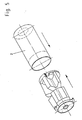
- the sleeve rubber spring shown in Figures 1 and 2 consists of the spring body 3 made of rubber, which is connected by vulcanization to the inner support sleeve 1 and inserted under radial compression in the outer support sleeve 2.
- the inner and outer support sleeves 1, 2 consist of pipes made of metal. They are used to connect secondary machine parts to the sleeve rubber spring shown, for example the connection parts on the one hand the axle and on the other hand the body of a motor vehicle.
- the rubber used for the production of the spring body 3 is a common quality. It has a Shore A hardness of 50.
- the tubes have a rotationally symmetrical limited profile.
- the use of tubes with a different profile is also possible, for example with a triangular, quadrangular, pentagonal or hexagonal profile, with a circular or oval-limited profile or with transition forms between at least two of the aforementioned profile shapes.
- the spring body 3 has four essentially outwardly projecting webs, of which the webs 4 and 6 can be seen in FIG. 1.
- the webs together with the outer of the support sleeves 2 and the end walls 24 enclose liquid-filled chambers, of which the chamber 8 can be seen in FIG. 1 and all the chambers 8, 10, 9, 11 in FIG. 2.
- the chambers 8, 10 are separated by a Connection opening 12 connected, which is channel-shaped in a partial area and is enclosed in this partial area on the one hand by the profile of the end ring 15 arranged there and on the other hand by the oppositely angled profile 16 of the outer support sleeve 2.
- Recesses 25 of the leg of the corresponding end ring 15 pointing outward in the radial direction ensure the liquid transfer between the channel and the chambers 8 and 10, respectively. Consequently, liquid can be moved back and forth between the two to achieve a damping effect if there is a relative displacement of the inner support sleeve 1 in the outer support sleeve 2.
- a correspondingly effective channel 13 is provided at the opposite, axial end of the sleeve rubber spring. This connects the left chamber 11 with the chamber 9 arranged on the right in the same horizontal plane.
- the end walls 14 delimiting the chambers on the front side are of a resilient nature. When low-frequency vibrations of large amplitude are introduced, this results in a pressure difference in the individual chambers of the sleeve rubber spring, which leads to liquid being pressed through the connecting opening connecting the chambers and to achieving a large damping effect.
- the isolation of high-frequency vibrations of small amplitude is served by the thin membrane walls which separate the recesses 18 from the chambers 8 and 10.
- the recesses can be not only blind-hole-like, but also completely continuous, in both cases the size of the extension transverse to the direction of force application in conjunction with the distance between the walls opposite each other in the direction of force application defines the size of the small amplitude of isolated vibrations and of the large amplitude dampened vibrations.
- the properties resulting with respect to the isolation of high-frequency vibrations are accordingly equally excellent, as are the damping properties with regard to low-frequency vibrations.
- a mixture of glycol and water is used as the liquid in the sleeve rubber spring.
- the metallic parts of the sleeve rubber spring are therefore provided with a corrosion-preventing surface coating to avoid corrosion, expediently one based on rubber.
- FIG. 2 The shape of the spring body made of rubber produced during manufacture is illustrated by FIG. 2. It shows the spring body shown in FIG. 1 in the fully assembled state in a form taken from the outer support sleeve 2 in a cross-sectional view. It can be clearly seen that the radial extension of the webs 4, 5, 6, 7 exceeds that of the invisible end ring 15. The latter has an outer diameter which corresponds to the inner diameter of the outer support sleeve 2. The insertion of the spring body shown in the outer support sleeve 2 consequently requires a radial compression and thus a positive prestressing of the spring body 3 and in particular of the webs 4, 5, 6 and 7. The durability is thus significantly increased when fully assembled. It can also be seen that the webs 4, 5, 6, 7 are assigned in mirror image to an imaginary vertical plane erected in the axis of the inner support sleeve 1.
- the webs 4, 5 arranged above the center line of the inner support sleeve 1 enclose a greater angle with one another than the lower webs 6, 7.
- the latter also have a greater extent in the circumferential direction than the webs 4, 5.
- the radial extent is in all cases consistent.
- the sheets 14, 5, 6, 7, which delimit the webs 4 after their manufacture, thus have a corresponding distance from the inner support sleeve 1 before insertion into the outer support sleeve 2. The situation in this regard changes during insertion into the outer support sleeve 2.
- FIG. 1 shows the sleeve rubber spring in the unloaded state.
- the relative displacement A of the support sleeves resulting from the compression of the spring body is also entered.
- FIG. 3 shows the spring body 3 shown in cross section in FIG. 2 in a view from the side. This is to make it clear that the spring body is produced so that the webs 4, 5, 6, 7 each from partial webs 4 '; 5 ′; 6 ′; and 7 'exist, which have a mutual axial distance from each other in the central region of their axial extension, which increases in the radial direction to the outside.
- the distance is substantially eliminated during the insertion of the spring body into the outer of the support sleeves, so that the mutually facing end faces 30 of the partial webs 4 ', 5', 6 ', 7' enter into a mutual sealing system.
- liquid can therefore at least not pass through the gap formed by the distance in a functionally disruptive manner.
- the gap is completely sealed, which can be caused by pressing together the opposite end faces 30 in the axial direction of the webs 4 ', 5', 6 'and 7'.
- the simplest way to achieve a corresponding effect consists in a corresponding dimensional match between the production-related length of the spring body 3 made of rubber and the axial length of the outer support sleeve 2 which finally receives the spring body.
- the end walls 24 are convex inward in the production-related shape shown arched.
- the partial webs 4 ', 5', 6 ', 7' are provided on their side pointing outward in the radial direction with metal pads 14 fixed by vulcanization. These are formed by sheets and have a slightly smaller extension than the partial webs 4 ', 5', 6 ', 7'. They are adapted radially on the outside to the shape of the inner wall of the outer sleeve 2.
- the insertion of the rubber body shown in Figures 2 and 3 into the outer support sleeve 2 is illustrated by Figure 4.
- the joining process is expediently carried out in a submerged state.
- the outer support sleeve 2 used consists of a tube made of metal.
- This has an inwardly directed flange projection at the right end, which can be produced, for example, by a crimp.
- the left end is open axially so that the rubber body 3 including the inner support sleeve 1 fixed therein by vulcanization can be inserted until its right end strikes the flange projection of the outer support sleeve.
- the relative displacement continues until, in addition to an elastic reduction in the radial extent of the partial webs 4, 5, 6, 7, there is mutual compression of their end faces 30 lying opposite in the axial direction.
- the joining process is completed by generating an inward crimp at the left end of the outer support sleeve 2.
- the crimp can correspond to the annular flange projection already present at the right end.
- the joining process shown in FIG. 5 corresponds in detail to that described above.
- a spring body made of rubber is used, in which the partial webs have an enlarged extension in the radial direction axially in the direction of the center of the spring body. Compared to the joining process described above, this results in a greater radial compression in the central area.
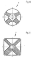
- FIGS. 6 to 11 show different designs of ready-to-use sleeve rubber springs under load in a cross-sectional illustration.
- the mutually surrounding support sleeves are formed by tubes in the embodiments according to FIGS. 6 to 9 and are of rotationally symmetrical shape.
- only one of the support sleeves is produced from a tube, while the other has a non-rotationally symmetrical surface, at least on the side adjoining the spring body. This effectively prevents unwanted relative displacement of the immediately adjacent rubber spring body in the circumferential direction.
- the non-parallel, mutual assignment of the surfaces lying opposite one another gives the support sleeves the possibility of setting the spring rates of the individual webs in a targeted manner.
- FIG. 10 and 11 show different designs of ready-to-use sleeve rubber springs under load in a cross-sectional illustration.
- the mutually surrounding support sleeves are formed by tubes in the embodiments according to FIGS. 6 to 9 and are of rotationally symmetrical shape.
- only one of the support sleeves is produced from a tube
- the outer support sleeve consists of a rectangular tube, which is delimited in four directions by flat outer surfaces. This makes it easier to weld or screw the sleeve rubber spring onto load-bearing structures. To achieve corresponding effects, it may also be advisable to structure the support sleeves in relief-like manner on at least one of the surfaces facing one another, for example in the direction of the axis of the sleeve rubber spring. In this case, axially consecutive areas of different diameters result.
- the rubber spring bodies used in the designs according to FIGS. 6 to 11 have profiles which differ from one another.
- the two support sleeves enclosing one another are merely connected by two webs which enclose an angle of approximately 90 °.
- a stop buffer 31 is provided in the loading plane for limiting the maximum evasive movement. This is assigned to the profile of each of the two webs at an angle of approximately 135 °.
- 3 webs are evenly distributed over the circumference.
- One of these webs has a central plane which is arranged in the load plane. It is of reduced cross-section.
- Figure 8 shows an embodiment in which the individual webs are in turn evenly distributed over the circumference. However, the lower of the two webs have a greater extent in the circumferential direction than the upper webs. This results in the desired relative displacement of the inner support sleeve in the vertical direction upwards during the compression provided according to the invention.
- a similar effect occurs during the compression according to the invention in the embodiment according to FIG. 9.
- five webs are distributed over the circumference of the sleeve rubber spring, the lower one of which has the greatest extent in the circumferential direction, followed by the two webs lying opposite one another, which extend in the horizontal direction and finally from the two webs pointing upwards, which have the smallest circumferential extent of all webs in the circumferential direction.
- the design ensures a particularly precise guidance of the two surrounding support sleeves transversely to the main direction of introduction of the forces to be absorbed.
- the structure described above has a positive effect on a certain liquid damping in this direction, which is caused by the fact that the liquid-filled chambers 22, 23 are each connected to the liquid-filled chamber 21 by a damping connecting line.
- the air-filled cavities 19 also have a positive influence on this. They are connected to the atmosphere by throttle openings 20 of narrow cross section.
- Figures 12 and 13 two different versions of spring bodies are shown in a longitudinal section, the drawings being carried out in such a way that in the upper part of each representation the spring body is shown in the non-compressed state and in the lower part of the representation in the compressed state.
- the designs can be used with any or any of the cross-sectional shapes described above.
- the webs of the spring body are divided in the middle, the division being carried out in such a way that the partial web 4 ⁇ shown on the left is assigned to the axis of the inner of the support sleeves 1 at a steeper angle than that in the right part before it is compressed the partial web 4 'shown.
- the prestress caused in the spring body by the compression is not compensated in the axial direction and is designed such that greater forces can be introduced into the inner support sleeve 1 of the ready-made sleeve rubber spring, which are effective in a direction to the right than in the opposite direction.
- Such a sleeve rubber spring can thus give the connected machine element good guidance and relative mobility not only in the radial direction but also in the axial direction.
- FIG. 13 is similar in terms of its basic structure to the embodiment according to FIG. 12 described above.
- the partial webs 4 ⁇ and 4 ' are of different lengths, which means that the load-bearing capacity of the operational sleeve rubber spring is greater than in the case described above in relation to forces which are introduced right-hand into the inner support sleeve 1.
- the radial preload corresponds to that described above.
- Such a design is ideal for applications in which a particularly large, axially directed, static preload is superimposed on a large, radially directed preload.
- Such an application is for example in the area of the axle suspension of a motor vehicle. Due to the split design of the inner support sleeve in the axial direction and the two spring bodies connected to it, this results in a particularly simple manufacture.
- This consists of two partial support sleeves 1 ', which are connected in a liquid-tight manner in the parting plane of the partial webs 4' 4 'by means of an interference fit.
Landscapes
- Engineering & Computer Science (AREA)
- General Engineering & Computer Science (AREA)
- Mechanical Engineering (AREA)
- Combined Devices Of Dampers And Springs (AREA)
- Arrangement Or Mounting Of Propulsion Units For Vehicles (AREA)
- Springs (AREA)
Applications Claiming Priority (2)
| Application Number | Priority Date | Filing Date | Title |
|---|---|---|---|
| DE3724432 | 1987-07-23 | ||
| DE19873724432 DE3724432A1 (de) | 1987-07-23 | 1987-07-23 | Huelsengummifeder |
Publications (2)
| Publication Number | Publication Date |
|---|---|
| EP0300090A2 true EP0300090A2 (fr) | 1989-01-25 |
| EP0300090A3 EP0300090A3 (fr) | 1989-03-22 |
Family
ID=6332224
Family Applications (1)
| Application Number | Title | Priority Date | Filing Date |
|---|---|---|---|
| EP87116640A Withdrawn EP0300090A3 (fr) | 1987-07-23 | 1987-11-11 | Ressort du type à manchon en caoutchouc |
Country Status (4)
| Country | Link |
|---|---|
| US (1) | US4840359A (fr) |
| EP (1) | EP0300090A3 (fr) |
| JP (1) | JP2809230B2 (fr) |
| DE (1) | DE3724432A1 (fr) |
Cited By (4)
| Publication number | Priority date | Publication date | Assignee | Title |
|---|---|---|---|---|
| EP0332901A3 (en) * | 1988-03-15 | 1990-03-21 | Metzeler Gesellschaft Mit Beschrankter Haftung | Elastic and hydraulically damped sleeve |
| FR2655113A1 (fr) * | 1989-11-29 | 1991-05-31 | Nissan Motor | Dispositif d'amortissement en elastomere rempli d'un fluide. |
| DE102007015239A1 (de) * | 2007-03-29 | 2008-10-02 | Trelleborg Automotive Technical Centre Gmbh | Elastische Lagerbuchse |
| EP2881615A4 (fr) * | 2012-08-03 | 2016-05-18 | Bridgestone Corp | Dispositif d'amortissement de vibrations |
Families Citing this family (41)
| Publication number | Priority date | Publication date | Assignee | Title |
|---|---|---|---|---|
| JPH0639151Y2 (ja) * | 1988-03-15 | 1994-10-12 | エヌ・オー・ケー・メグラスティック株式会社 | 液体封入ブッシュ |
| DE3827905A1 (de) * | 1988-08-17 | 1990-03-08 | Boge Ag | Hydraulisch daempfendes gummilager |
| DE3905686C1 (fr) * | 1989-02-24 | 1990-06-07 | Fa. Carl Freudenberg, 6940 Weinheim, De | |
| DE3909609A1 (de) * | 1989-03-23 | 1990-10-04 | Freudenberg Carl Fa | Huelsengummifeder |
| US5221077A (en) * | 1989-05-15 | 1993-06-22 | Bridgestone Corporation | Vibration isolating apparatus |
| JP2894497B2 (ja) * | 1989-05-15 | 1999-05-24 | 株式会社ブリヂストン | 防振装置 |
| US5170997A (en) * | 1989-11-30 | 1992-12-15 | Hutchinson | Resilient articulation with variable stiffness |
| JPH0747975B2 (ja) * | 1989-12-19 | 1995-05-24 | 東海ゴム工業株式会社 | ダンパー付筒型マウント装置 |
| US5213313A (en) * | 1990-07-19 | 1993-05-25 | Tokai Rubber Industries, Ltd. | Fluid-filled cylindrical elastic mount having lateral and radial elastic walls for desired axial and diametric spring characteristics |
| FR2669091B1 (fr) * | 1990-11-13 | 1995-02-17 | Hutchinson | Perfectionnements apportes aux manchons antivibratoires hydrauliques. |
| DE4039228C1 (fr) * | 1990-12-08 | 1991-12-05 | Fa. Carl Freudenberg, 6940 Weinheim, De | |
| JPH04271831A (ja) * | 1991-01-18 | 1992-09-28 | Nippon Steel Corp | 空気清浄化物の製造方法 |
| JP2528149Y2 (ja) * | 1991-03-20 | 1997-03-05 | 東海ゴム工業株式会社 | メンバーマウント |
| JP2678705B2 (ja) * | 1992-02-25 | 1997-11-17 | 東海ゴム工業株式会社 | 流体封入式筒型マウント |
| US5389905A (en) * | 1992-04-22 | 1995-02-14 | Matsushita Electric Works, Ltd. | Damper, electromagnet assembly employing the damper, and relay employing the electromagnet assemblies |
| DE4305808C2 (de) * | 1993-02-25 | 1995-05-11 | Freudenberg Carl Fa | Hydraulisch dämpfende Hülsengummifeder |
| FR2713731B1 (fr) * | 1993-12-09 | 1996-02-09 | Hutchinson | Perfectionnement aux supports antivibratoires hydrauliques et à leurs procédés de fabrication. |
| DE4426588C5 (de) * | 1994-07-27 | 2004-10-28 | Woco Avs Gmbh | Querweiche Tragfeder für ein Hydrolager |
| DE4438931C2 (de) * | 1994-10-31 | 1997-09-11 | Daimler Benz Ag | Hydrolager |
| FR2728949A1 (fr) * | 1995-01-04 | 1996-07-05 | Hutchinson | Perfectionnements aux manchons de support antivibratoires hydrauliques |
| FR2777613B1 (fr) * | 1998-04-21 | 2000-06-16 | Hutchinson | Manchon elastique a deux armatures; bielette de reprise de couple equipee d'un tel manchon |
| US6101435A (en) * | 1998-06-01 | 2000-08-08 | Ford Global Technologies, Inc. | Method for compensating a power assist steering system control signal |
| JP2002168288A (ja) * | 2000-09-20 | 2002-06-14 | Toyo Tire & Rubber Co Ltd | 防振装置 |
| JP2002274137A (ja) * | 2001-03-15 | 2002-09-25 | Tokai Rubber Ind Ltd | サスペンションサポート |
| JP4073648B2 (ja) * | 2001-09-06 | 2008-04-09 | 東洋ゴム工業株式会社 | 液封入式防振装置 |
| FR2849907B1 (fr) * | 2003-01-09 | 2006-08-18 | Hutchinson | Articulation antivibratoire hydraulique a butees axiales, vehicule equipe d'une telle articulation, et procede de fabrication d'une telle articulation |
| DE10351229B4 (de) * | 2003-11-03 | 2006-01-19 | Trelleborg Automotive Technical Centre Gmbh | Hydraulisch dämpfendes Lager |
| FR2868140B1 (fr) * | 2004-03-29 | 2008-03-07 | Hutchinson Sa | Dispositif antivibratoire pour vehicule et biellette comportant un tel dispositif |
| FR2876428B1 (fr) * | 2004-10-11 | 2008-08-08 | Hutchinson Sa | Dispositif antivibratoire et vehicule comportant un tel dispositif |
| JP4645504B2 (ja) * | 2006-03-30 | 2011-03-09 | 東海ゴム工業株式会社 | 防振装置 |
| JP4382822B2 (ja) * | 2007-01-11 | 2009-12-16 | 本田技研工業株式会社 | 筒形防振装置 |
| JP4881781B2 (ja) * | 2007-03-30 | 2012-02-22 | 東海ゴム工業株式会社 | トルクロッドの製造方法 |
| DE102010015579B4 (de) | 2010-04-19 | 2012-10-25 | Carl Freudenberg Kg | Entkoppelte Hydrobuchse |
| WO2012043483A1 (fr) * | 2010-09-27 | 2012-04-05 | 株式会社ブリヂストン | Dispositif d'amortissement de vibrations |
| US20130175748A1 (en) * | 2012-01-06 | 2013-07-11 | Honda Motor Co., Ltd. | Compliance bush at trailing arm |
| EP2672137A1 (fr) * | 2012-06-06 | 2013-12-11 | Firma Carl Freudenberg | Couche hydraulique |
| DE102013209990A1 (de) * | 2013-05-29 | 2014-12-04 | Zf Friedrichshafen Ag | Hydraulisch dämpfendes Gummilager |
| DE102014216070A1 (de) | 2014-08-13 | 2016-02-18 | Boge Elastmetall Gmbh | Aggregatlager, insbesondere für ein Kraftfahrzeug |
| JP2017219103A (ja) * | 2016-06-07 | 2017-12-14 | Nok株式会社 | 防振ブッシュ |
| JP7060531B2 (ja) * | 2019-02-15 | 2022-04-26 | 本田技研工業株式会社 | 液封ブッシュ |
| CN111706639B (zh) * | 2020-05-27 | 2022-03-29 | 株洲时代新材料科技股份有限公司 | 一种液压复合衬套、用于其的流道及流道的形成方法 |
Family Cites Families (29)
| Publication number | Priority date | Publication date | Assignee | Title |
|---|---|---|---|---|
| DE690476C (de) * | 1937-02-16 | 1940-04-26 | Continental Gummi Werke Akt Ge | Lager- und Federbuchse |
| US2267172A (en) * | 1938-05-17 | 1941-12-23 | Firestone Tire & Rubber Co | Resilient mounting |
| US2706126A (en) * | 1949-07-08 | 1955-04-12 | Leon F Thiry | Vibration mountings |
| US2658710A (en) * | 1950-05-04 | 1953-11-10 | Robinson Aviat Inc | Vibration isolation unit |
| US3028665A (en) * | 1957-11-12 | 1962-04-10 | Metalastik Ltd | Method of making a resilient mounting |
| US2959437A (en) * | 1958-05-24 | 1960-11-08 | Riv Officine Di Villar Perosa | Resilient bearing |
| US3642268A (en) * | 1968-08-26 | 1972-02-15 | Gen Tire & Rubber Co | High-damping resilient bushing |
| DE2036160A1 (de) * | 1969-08-04 | 1971-02-25 | Riv Officine Di Villar Perosa | Elastisches Gelenk |
| US3698703A (en) * | 1970-11-23 | 1972-10-17 | Gen Tire & Rubber Co | Dual rate fluid damped elastomeric bushing |
| JPS589781Y2 (ja) * | 1976-08-12 | 1983-02-22 | 東海ゴム工業株式会社 | 自動車用エンジン支持装置 |
| US4183496A (en) * | 1978-08-30 | 1980-01-15 | Chrysler Corporation | Low ratio engine mounting |
| DE2841505C2 (de) * | 1978-09-23 | 1983-04-07 | Boge Gmbh, 5208 Eitorf | Hydraulisch dämpfendes Gummilager |
| JPS57200741A (en) * | 1981-06-03 | 1982-12-09 | Nissan Motor Co Ltd | Power unit mount body of car |
| JPS5881249A (ja) * | 1981-11-10 | 1983-05-16 | Kinugawa Rubber Ind Co Ltd | 防振ブツシユ |
| JPS58170610A (ja) * | 1982-03-31 | 1983-10-07 | Toyota Motor Corp | サスペンシヨンブツシユ構造 |
| US4489921A (en) * | 1982-10-29 | 1984-12-25 | The Standard Products Company | Resilient engine mount |
| JPS60168931A (ja) * | 1984-02-08 | 1985-09-02 | Nissan Motor Co Ltd | 流体封入防振装置 |
| JPS60175836A (ja) * | 1984-02-22 | 1985-09-10 | Toyota Motor Corp | 防振ゴムマウント |
| AU555483B2 (en) * | 1984-04-05 | 1986-09-25 | Bridgestone Corporation | Liquid filled elastomeric bushings |
| DE3566023D1 (en) * | 1984-08-07 | 1988-12-08 | Avon Ind Polymers | Hydraulically damped mounting device |
| DE3445491C1 (de) * | 1984-12-13 | 1986-04-10 | Wegu Gummi- und Kunststoffwerke Walter Dräbing KG, 3500 Kassel | Lager fuer eine Abgasanlage eines Kraftfahrzeuges |
| JPS61206838A (ja) * | 1985-03-07 | 1986-09-13 | Tokai Rubber Ind Ltd | 流体入りブツシユ組立体 |
| EP0199240B2 (fr) * | 1985-04-19 | 1994-10-12 | METZELER Gesellschaft mit beschränkter Haftung | Elément de support à amortissement hydraulique pouvant être précontraint |
| JPH0689806B2 (ja) * | 1986-01-20 | 1994-11-14 | 株式会社ブリヂストン | 防振装置 |
| FR2599450B1 (fr) * | 1986-06-03 | 1990-08-10 | Hutchinson | Perfectionnements apportes aux manchons de support antivibratoires hydrauliques |
| JPS63141A (ja) * | 1986-06-19 | 1988-01-05 | Fujitsu Ltd | 半導体記憶装置 |
| JPS63145837A (ja) * | 1986-07-04 | 1988-06-17 | Tokai Rubber Ind Ltd | 円筒型流体封入式防振支持体 |
| GB2192968B (en) * | 1986-07-23 | 1990-03-21 | Clevite Ind Inc | Fluid filled elastomeric damping device |
| US4762310A (en) * | 1987-08-31 | 1988-08-09 | General Motors Corporation | Pivot bushing assembly application |
-
1987
- 1987-07-23 DE DE19873724432 patent/DE3724432A1/de not_active Withdrawn
- 1987-11-11 EP EP87116640A patent/EP0300090A3/fr not_active Withdrawn
-
1988
- 1988-04-14 US US07/181,558 patent/US4840359A/en not_active Expired - Lifetime
- 1988-07-22 JP JP63183410A patent/JP2809230B2/ja not_active Expired - Lifetime
Cited By (7)
| Publication number | Priority date | Publication date | Assignee | Title |
|---|---|---|---|---|
| EP0332901A3 (en) * | 1988-03-15 | 1990-03-21 | Metzeler Gesellschaft Mit Beschrankter Haftung | Elastic and hydraulically damped sleeve |
| FR2655113A1 (fr) * | 1989-11-29 | 1991-05-31 | Nissan Motor | Dispositif d'amortissement en elastomere rempli d'un fluide. |
| DE102007015239A1 (de) * | 2007-03-29 | 2008-10-02 | Trelleborg Automotive Technical Centre Gmbh | Elastische Lagerbuchse |
| WO2008119652A1 (fr) * | 2007-03-29 | 2008-10-09 | Trelleborg Automotive Technical Centre Gmbh | Coussinet élastique |
| DE102007015239B4 (de) * | 2007-03-29 | 2012-03-29 | Trelleborg Automotive Germany Gmbh | Elastische Lagerbuchse |
| EP2881615A4 (fr) * | 2012-08-03 | 2016-05-18 | Bridgestone Corp | Dispositif d'amortissement de vibrations |
| US9366308B2 (en) | 2012-08-03 | 2016-06-14 | Bridgestone Corporation | Vibration damping device |
Also Published As
| Publication number | Publication date |
|---|---|
| DE3724432A1 (de) | 1989-02-02 |
| EP0300090A3 (fr) | 1989-03-22 |
| JPS6446029A (en) | 1989-02-20 |
| JP2809230B2 (ja) | 1998-10-08 |
| US4840359A (en) | 1989-06-20 |
Similar Documents
| Publication | Publication Date | Title |
|---|---|---|
| DE3724432A1 (de) | Huelsengummifeder | |
| DE3724431C2 (fr) | ||
| DE3823238C2 (fr) | ||
| DE3840176C2 (fr) | ||
| DE10131075B4 (de) | Aggregatelager in Buchsenform | |
| EP1736681B1 (fr) | Manchon avec butée radiale et/ou axiale et procédé pour la réalisation d'une butée axiale d'un manchon | |
| DE19624886A1 (de) | Flüssigkeitsdämpfungsvorrichtung mit großen Federsteifigkeitswerten in zwei zueinander senkrechten Richtungen | |
| EP2142821B1 (fr) | Douille élastomère à amortissement hydraulique | |
| EP0159385A1 (fr) | Bague d'étanchéité, manchon avec bague d'étanchéité et son utilisation | |
| DE10036740A1 (de) | Schwingungsdämpfungseinrichtung, deren elastischer Körper eine gute Haltbarkeit aufweist | |
| EP0199240A2 (fr) | Elément de support à amortissement hydraulique pouvant être précontraint | |
| DE10241246B4 (de) | Elastisches Gummilager | |
| WO2006029606A1 (fr) | Palier elastomere | |
| DE69908482T2 (de) | Hülsengummifeder mit zwei Armaturen; Drehmomentenanlaufschwingarm mit solcher Hülse | |
| DE102010041217B4 (de) | Elastomeres Buchsenlager mit Außenhülse aus Kunststoff | |
| DE102018106365A1 (de) | Lageranordnung | |
| DE3414821C2 (de) | Dichtungsanordnung | |
| DE102020105248B4 (de) | Lageranordnung mit einem Kernelement für ein Fahrzeug | |
| WO2001073315A1 (fr) | Support elastique a comportement d'amortissement graduel | |
| DE102009022841B4 (de) | Elastisches Federbeinkopflager für ein Kraftfahrzeug und Verfahren zum Einstellen einer Druckvorspannung in einem elastischen Ringkörper des Federbeinkopflagers | |
| DE1034421B (de) | Elastisches Gelenk | |
| DE19910308B4 (de) | Hydraulisch dämpfendes Gummilager mit Axialanschlägen sowie ein Verfahren zur Herstellung eines solchen hydraulisch dämpfenden Gummilagers mit integrierten Axialanschlägen | |
| DE69015985T2 (de) | Strebe. | |
| DE102019000973B4 (de) | Lager zur Schwingungsentkoppelung und Verfahren zum Herstellen | |
| DE102022116262A1 (de) | Elastisches Lager mit reduzierter Versteifung bei hochfrequenter Beanspruchung |
Legal Events
| Date | Code | Title | Description |
|---|---|---|---|
| PUAI | Public reference made under article 153(3) epc to a published international application that has entered the european phase |
Free format text: ORIGINAL CODE: 0009012 |
|
| AK | Designated contracting states |
Kind code of ref document: A2 Designated state(s): DE FR GB IT |
|
| PUAL | Search report despatched |
Free format text: ORIGINAL CODE: 0009013 |
|
| AK | Designated contracting states |
Kind code of ref document: A3 Designated state(s): DE FR GB IT |
|
| 17P | Request for examination filed |
Effective date: 19890221 |
|
| 17Q | First examination report despatched |
Effective date: 19900306 |
|
| STAA | Information on the status of an ep patent application or granted ep patent |
Free format text: STATUS: THE APPLICATION HAS BEEN WITHDRAWN |
|
| 18W | Application withdrawn |
Withdrawal date: 19900628 |
|
| R18W | Application withdrawn (corrected) |
Effective date: 19900628 |
|
| RIN1 | Information on inventor provided before grant (corrected) |
Inventor name: RUDOLPH, AXEL Inventor name: HAMAEKERS, ARNO |