EP0300348A2 - Réacteur pour le biogaz - Google Patents
Réacteur pour le biogaz Download PDFInfo
- Publication number
- EP0300348A2 EP0300348A2 EP19880111209 EP88111209A EP0300348A2 EP 0300348 A2 EP0300348 A2 EP 0300348A2 EP 19880111209 EP19880111209 EP 19880111209 EP 88111209 A EP88111209 A EP 88111209A EP 0300348 A2 EP0300348 A2 EP 0300348A2
- Authority
- EP
- European Patent Office
- Prior art keywords
- funnel
- gas
- reactor
- section
- tube
- Prior art date
- Legal status (The legal status is an assumption and is not a legal conclusion. Google has not performed a legal analysis and makes no representation as to the accuracy of the status listed.)
- Granted
Links
Images


Classifications
-
- C—CHEMISTRY; METALLURGY
- C02—TREATMENT OF WATER, WASTE WATER, SEWAGE, OR SLUDGE
- C02F—TREATMENT OF WATER, WASTE WATER, SEWAGE, OR SLUDGE
- C02F3/00—Biological treatment of water, waste water, or sewage
- C02F3/28—Anaerobic digestion processes
- C02F3/2846—Anaerobic digestion processes using upflow anaerobic sludge blanket [UASB] reactors
-
- C—CHEMISTRY; METALLURGY
- C12—BIOCHEMISTRY; BEER; SPIRITS; WINE; VINEGAR; MICROBIOLOGY; ENZYMOLOGY; MUTATION OR GENETIC ENGINEERING
- C12M—APPARATUS FOR ENZYMOLOGY OR MICROBIOLOGY; APPARATUS FOR CULTURING MICROORGANISMS FOR PRODUCING BIOMASS, FOR GROWING CELLS OR FOR OBTAINING FERMENTATION OR METABOLIC PRODUCTS, i.e. BIOREACTORS OR FERMENTERS
- C12M21/00—Bioreactors or fermenters specially adapted for specific uses
- C12M21/04—Bioreactors or fermenters specially adapted for specific uses for producing gas, e.g. biogas
-
- C—CHEMISTRY; METALLURGY
- C12—BIOCHEMISTRY; BEER; SPIRITS; WINE; VINEGAR; MICROBIOLOGY; ENZYMOLOGY; MUTATION OR GENETIC ENGINEERING
- C12M—APPARATUS FOR ENZYMOLOGY OR MICROBIOLOGY; APPARATUS FOR CULTURING MICROORGANISMS FOR PRODUCING BIOMASS, FOR GROWING CELLS OR FOR OBTAINING FERMENTATION OR METABOLIC PRODUCTS, i.e. BIOREACTORS OR FERMENTERS
- C12M23/00—Constructional details, e.g. recesses, hinges
- C12M23/36—Means for collection or storage of gas; Gas holders
-
- C—CHEMISTRY; METALLURGY
- C12—BIOCHEMISTRY; BEER; SPIRITS; WINE; VINEGAR; MICROBIOLOGY; ENZYMOLOGY; MUTATION OR GENETIC ENGINEERING
- C12M—APPARATUS FOR ENZYMOLOGY OR MICROBIOLOGY; APPARATUS FOR CULTURING MICROORGANISMS FOR PRODUCING BIOMASS, FOR GROWING CELLS OR FOR OBTAINING FERMENTATION OR METABOLIC PRODUCTS, i.e. BIOREACTORS OR FERMENTERS
- C12M27/00—Means for mixing, agitating or circulating fluids in the vessel
- C12M27/18—Flow directing inserts
- C12M27/20—Baffles; Ribs; Ribbons; Auger vanes
-
- C—CHEMISTRY; METALLURGY
- C12—BIOCHEMISTRY; BEER; SPIRITS; WINE; VINEGAR; MICROBIOLOGY; ENZYMOLOGY; MUTATION OR GENETIC ENGINEERING
- C12M—APPARATUS FOR ENZYMOLOGY OR MICROBIOLOGY; APPARATUS FOR CULTURING MICROORGANISMS FOR PRODUCING BIOMASS, FOR GROWING CELLS OR FOR OBTAINING FERMENTATION OR METABOLIC PRODUCTS, i.e. BIOREACTORS OR FERMENTERS
- C12M27/00—Means for mixing, agitating or circulating fluids in the vessel
- C12M27/18—Flow directing inserts
- C12M27/24—Draft tube
-
- Y—GENERAL TAGGING OF NEW TECHNOLOGICAL DEVELOPMENTS; GENERAL TAGGING OF CROSS-SECTIONAL TECHNOLOGIES SPANNING OVER SEVERAL SECTIONS OF THE IPC; TECHNICAL SUBJECTS COVERED BY FORMER USPC CROSS-REFERENCE ART COLLECTIONS [XRACs] AND DIGESTS
- Y02—TECHNOLOGIES OR APPLICATIONS FOR MITIGATION OR ADAPTATION AGAINST CLIMATE CHANGE
- Y02E—REDUCTION OF GREENHOUSE GAS [GHG] EMISSIONS, RELATED TO ENERGY GENERATION, TRANSMISSION OR DISTRIBUTION
- Y02E50/00—Technologies for the production of fuel of non-fossil origin
- Y02E50/30—Fuel from waste, e.g. synthetic alcohol or diesel
Definitions
- the invention relates to a biogas reactor, the housing of which is completely or partially filled with active biomass, in which, by means of one or more funnel-shaped separating elements in the reactor sections, a gas collecting space for collecting the gases rising from the fermentation suspension and a sedimentation space with little gas bubbles is formed in which the active biomass Can sediment sludge particles, the gas in the gas collection chamber being able to be discharged from the reactor by means of a line having a throttle element and / or being conducted via an overflow edge formed on the funnel-shaped separating element through a tube-like channel piece into the reactor chamber located above the funnel-shaped separating element, a number of funnel-shaped separating elements are arranged in a column-like manner one above the other in the housing of the reactor.
- biogas reactors organic substances are converted into biogas by the action of microorganisms as active biomass in CO2 and methane.
- high-rise reactors which are technically desirable due to their small footprint, the rising biogas accumulates with increasing height.
- flotation transports active biomass into the upper reactor zones and discharges it from the reactor.
- it is therefore necessary to limit the gas velocity and to extract biogas even in deeper reactor zones.
- efforts should be made to direct the flow in such a way that sedimentation zones are created in the different reactor heights. This is to be achieved according to DE-PS 33 26 879 by a biogas reactor of the type mentioned.
- the entire funnel is filled with gas, a relatively large volume of gas is accumulated in the gas collecting space. Since there is no reaction in this volume, this space is lost for the conversion processes in the biogas reactor.
- the separating elements formed by the double funnel arrangement are arranged one above the other at certain predetermined intervals, with a distance in the range of 1-5 m being suitable, the volume of the gas collecting spaces takes up an ever larger proportion of the total reactor volume with increasing reactor size. With a reactor diameter of z. B. 4 m there are already gas collection volumes of about 4-5 m3. A gas volume of this size generates considerable lift, which can only be mastered by constructively complex measures.
- the object of the invention is the generic. To improve the biogas reactor so that it has a simple column-like design with a small footprint, the buoyancy forces should be negligible at a high height, defined sedimentation zones should be created and biogas should be removable from all - even deeper - reactor zones.
- the object is achieved in that the funnels of the separating elements are connected to a pipe in such a way that the pipe section facing the liquid level protrudes from the funnel and forms a gas collecting space with a section of the funnel, from which the gas formed at the free end section of the pipe section The overflow edge of the gas can be flowed into the gas discharge duct formed by the pipe, and that the section of the funnel or the pipe section facing the gas collecting space is connected to the line for gas discharge.
- An embodiment of the invention is based on the features of claim 2.
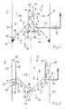
- the separating element 3 shows a separating element 3, which is surrounded by the wall 23 of a reactor housing 2.
- the separating element 3 consists of a central tube 9 on which a funnel 8 opening at the bottom is formed.
- the tube 9 is connected to the funnel 8 in such a way that a tube section 11 projects into the funnel space.
- the free end section 45 of the pipe section 11 is guided up to the liquid level 21.
- Above the liquid level 21 is the gas collecting space 7 formed by the tube section 21 and a section of the funnel 8.
- a gas deflector 17 is arranged to form a gap 18.
- B. can be designed as a guide ring.
- the housing section 15 formed above the funnel 8 serves as a sedimentation zone 16.
- the gas collecting space 7 is connected to a line 13 which is led out of the reactor housing 2.
- a valve 14 is located in line 13.
- the overflow edge 12 of the tube section 11 is arranged in the funnel 8 at a distance from the horizontal plane 66 formed by the free end section 19 of the funnel 8.
- the entire volume of the funnel 8 thus does not serve as a gas collecting space 7, but only a part.
- the gas 10 rising from the liquid is dammed up in the gas collecting space 7 and can be fed via the line 13 be discharged to the outside.
- Excess gas flows over the overflow edge 12 of the pipe section 11 into the open pipe 9, which forms a gas discharge channel 59.
- the gas bubbles 64 rising in the tube 9 produce an upward flow according to the mammoth pump principle.
- a downward flow occurs in the housing section 15 located laterally above the funnel 8 for reasons of continuity. Since this housing section 15 is shielded from gas rising from lower regions by the gas deflection device 17, a zone with favorable sedimentation properties is generated in the area of the housing section 15.
- FIG. 2 shows a further separating element 4.
- This consists of a tube 29 in which a funnel 28 is arranged.
- An opening is formed in the area of the funnel tip 26, in front of which a guide body 25 is arranged at a distance as a gas-repellent element.
- the funnel tip 26 projects downward from the horizontal plane 67 formed by the flow edge 32 of the pipe section 31.
- the tube 29 is connected to the funnel 28 in such a way that a tube section 31 projecting above the funnel 28 is formed, which serves as a guide surface 20 and forms the gas collecting space 7 with the associated section of the funnel 28.
- the overflow edge 32 formed on the free end section 45 of the pipe section 31 is in the liquid.
- an annular channel 24 is formed, which serves as a gas discharge channel 60.
- the upper end section 62 of the annular channel 24 is open, so that gas coming from the gas collecting space 7 can flow through the annular channel 24 into the space located above the separating element 4.
- the gas collecting space 7 is also connected to a line 13 with a valve 14, via which gas is discharged.
- the gas 10 rising from the liquid is collected on the outer surface 27 of the funnel 28 and accumulated in the gas collecting space 7. Excess gas flows over the overflow edge 32 into the ring channel 24 and from there reaches the top. In comparison to the separating element 3, the flow conditions in the separating element 4 are thus reversed.
- the sedimentation chamber 22 is formed in the tube 29 above the funnel 8.
- the separating element 4 has the advantage, with the same function, that no gas deflector is required on the wall 23 of the reactor housing 2. It is only necessary to provide the guide body 25 in the area of the opening 68 in the funnel tip 26, which prevents gas 10 from penetrating into the sedimentation chamber 22.
- a gap 69 is formed between the guide body 25 and the funnel tip 26, through which fluid can flow out of the sedimentation space 22. Furthermore, a biogas reactor with separating elements 4 is easier to manufacture than with separating elements 3, since the separating elements 4, in contrast to the separating elements 3, do not have to be fitted exactly into the reactor housing 2. The separating elements 4 can be arranged almost arbitrarily in a reactor housing 2 without losing their function.
- a funnel 38 is assigned to the funnel 8 instead of a tube section 11, forming a channel 36.
- This inner funnel 38 has a lower height than the outer funnel 8 and is connected to a line 13 with valve 14 for gas discharge.
- the cavity of the funnel 38 serves as a gas collecting space 7.
- the end section 19 of the funnel 8 is assigned a gas-repelling device 17, as has already been described for FIG.
- the outer edge of the funnel 38 serves as an overflow edge 37, via which the gas in the gas collecting space 7 can flow into the channel 36 and from there to the pipe 9.
- notches 33 can be provided on the overflow edges 12, 32, 37 (FIGS. 3 and 4).
- annular closure plate 34 In order to prevent gases emerging from a pipe 9 of a separating element 3 from entering directly into another pipe 9 of a separating element 3 located above, it is possible to provide an annular closure plate 34 on the free end section of the pipes 9 of the separating elements 3. In this case, it is necessary to provide at least one opening 35 as an outlet opening under the closure plate in the tube 9 (FIG. 4). Analogously, it is also possible to close the annular channel 24 of separating elements 4 with an annular closure plate, in which case openings 35 must also be formed in the tube 29 below the closure plate as outlet openings for gas.
- FIG. 5 shows an embodiment in which the tubes 9 of separating elements 3 of a biogas reactor 1 are connected to a central guide tube 41.
- a partition 40 must be arranged in the guide tube 41 between the partition elements 3 as a flow barrier.
- openings 42 in the guide tube 41 as gas inlet openings.
- at least one opening 35 is formed as a gas outlet opening (FIG. 5).
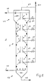
- FIG. 6 shows a biogas reactor 1 in which a plurality of separating elements 3 are arranged one above the other.
- a sedimentation chamber 49 is formed on the lower section 43 of the reactor housing 2 and is connected at its lowest point to a drain line 48.
- a waste water supply connection 46 is provided in the region of the lower section 43.
- the upper section 44 of the reactor housing 2 is also designed as a sedimentation space 50. This section has a larger diameter than the housing section of the reactor located underneath housing 2.
- the upper section 44 of the reactor housing 2 also has a drain port 47 and a gas line 64.
- Each gas collecting space 7 is connected by means of a line 13 with valve 14 to a central gas line 51, to which the gas line 64 already mentioned is also connected. However, it is also possible to connect only individual gas collection spaces 7 to the central gas line 51 by means of the line 13, provided that this is necessary or sufficient in the process provided in the biogas reactor 1.
- the biogas reactor 1 shown in FIG. 6 can have reactor heights between 5 and approximately 100 meters.
- the waste water to be fermented is fed to the biogas reactor 1 through the waste water feed pipe 46.
- the sedimentation chamber 49 in the lower section 43 of the reactor housing 2 serves to enrich excess sludge and inert, biologically inactive solids, which can then be drawn off via the drain line 48.
- the sedimentation and mechanical clarification of the purified wastewater to be discharged is promoted by increasing the reactor diameter.
- the biogas produced here is fed to the central gas line 51 via the gas line 64.
- a liquid level control device can e.g. B. have a level probe 52 which is guided into the gas collecting space 7 and is connected via a control unit with a valve 14 designed as a control valve.
- the valve 14 is arranged in the line 13, the inlet opening 55 of which is assigned to the relevant gas collecting space 7 to be controlled (FIG. 7). If an increase in the liquid level 21 is determined by means of the level probe 52, the valve 14 is adjusted in such a way that the gas located in the gas collecting space 7 presses the liquid level 21 down again (FIG. 7).
- FIG. 8 Another liquid level control device is shown in FIG. 8. This is designed as a float valve 58. It consists of a float housing 54 which is connected to the liquid space of the respective separating element by means of a connecting tube 56 and to the gas collecting space 7 by means of a line 65. A line 13 with a valve 14 is connected to the float housing 54. A float 57 is located in the float housing 54. The liquid level in the float housing 54 corresponds to the level of the liquid level 21.
- a valve body 53 is formed on the float 57, to which the inlet opening of the tube 13 is assigned as a valve seat. The valve body 53 may be adjustable, e.g. by adjusting the float 57.
- a reactor operation with a maximum gas removal, in which sedimentation is preferred, will normally preferably be installed in the upper reactor zones.
- Another can be used in the lower reactor zones to achieve good substrate mixing extreme operating condition may be required, in which all the gas rising from the lower reactor zones flows through the tubes 9 or annular channels 24 of the respective separating elements 3, 4. This state is achieved by closing the valves 14.
- the second-mentioned mode of operation tends to promote mixing. Due to the strong backmixing between upward and downward flow, the effect of sedimentation is largely suppressed.
- FIGS. 9a and 9b show another possible large version of a biogas reactor 70. Suitable diameters of this biogas reactor 70 are in the range from 5 to 15 m and are preferably approximately 9 m.
- the reactor height is between 15 and 50 m and is preferably 30 m.
- Separating elements 3, 71 are arranged in the reactor housing 2 of the biogas reactor 70 at a vertical distance from one another.
- the central separating element 3 has the shape of a circular cone as shown in FIG. 1.
- the separating element 71 is circular and has a triangular cross section, that is to say it is a curved triangular prism.
- the separating elements 3, 71 are held by vertically oriented pipes 9 which are connected to form central guide pipes 41.
- the tubes 9 or guide tubes 41 of the separating elements 71 are arranged in a ring (FIG. 9b).
- the tubes 9 have openings 42 for receiving the produced biogas or fermentation suspension, which is pumped upwards within the tubes 9 by the rising biogas.
- the gas-liquid mixture is discharged again into the reactor space outside the tubes 9.
- the tubes 9 are each closed by a partition 40.
- the lower one Separating elements 3, 71 are only assigned openings 42. Partitions 40 and openings 35 are omitted here.
- the openings 42 assigned to the uppermost separating elements 3, 71 are arranged higher than the openings 42 of the other separating elements 3, 71 and are located in the region of the gas collecting spaces 7 of the uppermost separating elements 3, 71. Through these openings 42, only gas is produced, but none Fermentation suspension directed.
- the liquid level 21 is predetermined by the extraction pressure for the biogas, which flows through the central gas line 51 as the extraction line. The liquid levels 21 are determined either by the opening state of the valves 14 or as a lower level limit by the horizontal planes corresponding to the openings 42.
- the separating elements 3, 71 of a cascade are connected to one another by at least one gas line 72.
- the resulting biogas is fed from the separating elements 71 through lines 13 with valves 14 to the central gas line 51.
- gas deflection devices 17 or guide bodies 25 are provided in order to keep rising gas bubbles away from the sedimentation zones 16 in the housing sections 15.
- Fresh substrate is supplied to the biogas reactor 70 via the waste water supply connection 46.
- the cleaned liquid is withdrawn from the biogas reactor 70 via the discharge nozzle 47.
- the drain line 48 is used for the removal of sludge or inert sedimented material. It is also possible to provide several separating elements 71 in each cascade instead of one separating element 71, the individual separating elements then having different diameters.
- gas lines 72 are provided in order to be able to discharge the biogas produced from the separating element 3 and the inner separating elements 71 via the outer separating element 71.
- the tubes 9 and the central guide tubes 41 are each arranged in such a way that they have approximately the same feed area so that the biogas reactor 70 can be operated uniformly.
- the funnel 8; 28; 8, 38 of the separating elements 3, 4, 5 have a prismatic, pyramidal or conical shape. It is also possible to combine different separating elements 3, 4, 5 in one biogas reactor 1.
- the separating element 5 can e.g. be used in such a reactor zone, in which it is intended that part of the rising gas should not be collected in the gas collecting space 7, but should be passed directly into the following reactor zone.
- the valves 14 By appropriately adjusting the valves 14, the separating elements 3, 4, 5, 71 in the individual reactor zones of the biogas reactor 1, 70 can be set so that the most uniform possible distribution of the active biomass within the reactor is achieved, the area of the discharge nozzle 47 being free of biomass.
Landscapes
- Life Sciences & Earth Sciences (AREA)
- Health & Medical Sciences (AREA)
- Engineering & Computer Science (AREA)
- Chemical & Material Sciences (AREA)
- Organic Chemistry (AREA)
- Zoology (AREA)
- Bioinformatics & Cheminformatics (AREA)
- Wood Science & Technology (AREA)
- Microbiology (AREA)
- Genetics & Genomics (AREA)
- General Health & Medical Sciences (AREA)
- Sustainable Development (AREA)
- Biochemistry (AREA)
- General Engineering & Computer Science (AREA)
- Biotechnology (AREA)
- Biomedical Technology (AREA)
- Molecular Biology (AREA)
- Environmental & Geological Engineering (AREA)
- Hydrology & Water Resources (AREA)
- Biodiversity & Conservation Biology (AREA)
- Water Supply & Treatment (AREA)
- General Chemical & Material Sciences (AREA)
- Clinical Laboratory Science (AREA)
- Oil, Petroleum & Natural Gas (AREA)
- Apparatus Associated With Microorganisms And Enzymes (AREA)
- Treatment Of Sludge (AREA)
- Organic Low-Molecular-Weight Compounds And Preparation Thereof (AREA)
- Devices And Processes Conducted In The Presence Of Fluids And Solid Particles (AREA)
- Gas Separation By Absorption (AREA)
Priority Applications (1)
| Application Number | Priority Date | Filing Date | Title |
|---|---|---|---|
| AT88111209T ATE70032T1 (de) | 1987-07-18 | 1988-07-13 | Biogasreaktor. |
Applications Claiming Priority (2)
| Application Number | Priority Date | Filing Date | Title |
|---|---|---|---|
| DE3723851 | 1987-07-18 | ||
| DE19873723851 DE3723851A1 (de) | 1987-07-18 | 1987-07-18 | Biogasreaktor |
Publications (3)
| Publication Number | Publication Date |
|---|---|
| EP0300348A2 true EP0300348A2 (fr) | 1989-01-25 |
| EP0300348A3 EP0300348A3 (en) | 1989-05-31 |
| EP0300348B1 EP0300348B1 (fr) | 1991-12-04 |
Family
ID=6331888
Family Applications (1)
| Application Number | Title | Priority Date | Filing Date |
|---|---|---|---|
| EP19880111209 Expired - Lifetime EP0300348B1 (fr) | 1987-07-18 | 1988-07-13 | Réacteur pour le biogaz |
Country Status (5)
| Country | Link |
|---|---|
| EP (1) | EP0300348B1 (fr) |
| JP (1) | JP2659403B2 (fr) |
| AT (1) | ATE70032T1 (fr) |
| DE (2) | DE3723851A1 (fr) |
| ES (1) | ES2028951T3 (fr) |
Cited By (9)
| Publication number | Priority date | Publication date | Assignee | Title |
|---|---|---|---|---|
| EP0808805A1 (fr) * | 1996-05-22 | 1997-11-26 | CT Umwelttechnik AG | Procédé et réacteur pour la purification anaérobie des eaux usées dans un lit de boue |
| EP0711732A3 (fr) * | 1994-11-08 | 1997-12-03 | Zeppelin Silo- und Apparatetechnik GmbH | Module pour un réacteur pour la purification anaérobie d'eau usée |
| EP1408009A1 (fr) * | 2002-10-11 | 2004-04-14 | VA TECH WABAG Deutschland GmbH & Co. KG | Réacteur à deux séparateurs de gaz et procédé anaérobie de traitement de liquides |
| US6929745B2 (en) * | 2000-06-30 | 2005-08-16 | Johan Verink | Apparatus for three-phase separation during treatment of wastewater and sludge |
| WO2010066379A1 (fr) * | 2008-12-10 | 2010-06-17 | Mcb Gmbh | Réacteur à flux ascendant à recirculation de biomasse commandée |
| EP2394966A1 (fr) * | 2010-05-19 | 2011-12-14 | Ambisys, s.a. | Appareil pour la rétention de (bio)solides et méthode pour le traitement de déchets au moyen dudit appareil |
| JP2012050910A (ja) * | 2010-08-31 | 2012-03-15 | Kobelco Eco-Solutions Co Ltd | 上向流式の反応槽、該反応槽を用いた水処理方法、該反応槽を備える水処理装置 |
| DE202011106472U1 (de) * | 2011-09-29 | 2013-01-08 | 4Biogas Gmbh & Co. Kg | Biogasreaktor mit einem Reaktorbehälter |
| CN114455700A (zh) * | 2022-01-20 | 2022-05-10 | 扬州大学 | 一种厌氧反应器折流出水装置 |
Families Citing this family (4)
| Publication number | Priority date | Publication date | Assignee | Title |
|---|---|---|---|---|
| DE4213015C2 (de) * | 1992-04-21 | 1997-05-28 | Maerkl Herbert | Biogasreaktor |
| JP3955431B2 (ja) * | 2000-09-08 | 2007-08-08 | 株式会社荏原製作所 | 嫌気性処理方法及び装置 |
| JP4619937B2 (ja) * | 2005-12-12 | 2011-01-26 | 住友重機械エンバイロメント株式会社 | メタン発酵装置 |
| DE102019003875A1 (de) * | 2019-05-31 | 2020-12-03 | Hedrich Gmbh | Verfahren zur Sedimentationsverhinderung in Vakuumdosieranlagen |
Family Cites Families (13)
| Publication number | Priority date | Publication date | Assignee | Title |
|---|---|---|---|---|
| NL173738C (nl) * | 1978-05-23 | 1988-10-17 | Gist Brocades Nv | Anaerobe zuiveringsinrichting. |
| JPS56100698A (en) * | 1980-01-12 | 1981-08-12 | Kazumi Shiyudo | Inclined plate in methane fermentation vessel |
| NL8004724A (nl) * | 1980-08-20 | 1982-03-16 | Bastiaan Bernard Boele Eertink | Inrichting en werkwijze voor het reinigen van afvalwater. |
| AT377250B (de) * | 1980-09-22 | 1985-02-25 | Weymelka Walter | Anlage zur bereitung von biogas |
| DD200133A1 (de) * | 1981-08-19 | 1983-03-23 | Friedrich Liepe | Vorrichtung zur anaeroben behandlung von schlaemmen und abwaessern |
| DE3222218C2 (de) * | 1982-06-12 | 1992-10-22 | Lehrter Zucker AG, 3160 Lehrte | Vorzugsweise kubischer Reaktionsbehälter zur anaeroben Abwasserreinigung |
| US4613433A (en) * | 1982-12-24 | 1986-09-23 | Biomass Limited | Anaerobic fermentor |
| DE3323915A1 (de) * | 1983-07-02 | 1985-01-10 | Johannes Dipl.-Ing. 8967 Oy-Mittelberg Cürten | Verfahren und vorrichtung zur gewinnung von biogas mit erhoehtem methananteil |
| DE3326879C2 (de) * | 1983-07-26 | 1986-10-02 | Herbert Dr.-Ing. 8047 Karlsfeld Märkl | Biogasreaktor |
| DE3330696A1 (de) * | 1983-08-25 | 1985-03-14 | Linde Ag, 6200 Wiesbaden | Anlage zum anaeroben abbau organischer substrate |
| GB8328598D0 (en) * | 1983-10-26 | 1983-11-30 | Univ Cardiff | Hydraulic digestion |
| DE3508274A1 (de) * | 1985-03-08 | 1986-09-11 | Kernforschungsanlage Jülich GmbH, 5170 Jülich | Saeulenreaktor fuer anaerobe abbauprozesse |
| FR2584738B1 (fr) * | 1985-07-15 | 1989-07-13 | Air Liquide | Procede de production d'anhydride carbonique et d'ethanol par fermentation continue, et appareillage de mise en oeuvre |
-
1987
- 1987-07-18 DE DE19873723851 patent/DE3723851A1/de not_active Withdrawn
-
1988
- 1988-06-28 JP JP16145188A patent/JP2659403B2/ja not_active Expired - Fee Related
- 1988-07-13 EP EP19880111209 patent/EP0300348B1/fr not_active Expired - Lifetime
- 1988-07-13 ES ES88111209T patent/ES2028951T3/es not_active Expired - Lifetime
- 1988-07-13 AT AT88111209T patent/ATE70032T1/de not_active IP Right Cessation
- 1988-07-13 DE DE8888111209T patent/DE3866619D1/de not_active Expired - Lifetime
Cited By (14)
| Publication number | Priority date | Publication date | Assignee | Title |
|---|---|---|---|---|
| EP0711732A3 (fr) * | 1994-11-08 | 1997-12-03 | Zeppelin Silo- und Apparatetechnik GmbH | Module pour un réacteur pour la purification anaérobie d'eau usée |
| EP0808805A1 (fr) * | 1996-05-22 | 1997-11-26 | CT Umwelttechnik AG | Procédé et réacteur pour la purification anaérobie des eaux usées dans un lit de boue |
| US6929745B2 (en) * | 2000-06-30 | 2005-08-16 | Johan Verink | Apparatus for three-phase separation during treatment of wastewater and sludge |
| EP1408009A1 (fr) * | 2002-10-11 | 2004-04-14 | VA TECH WABAG Deutschland GmbH & Co. KG | Réacteur à deux séparateurs de gaz et procédé anaérobie de traitement de liquides |
| WO2004035486A1 (fr) * | 2002-10-11 | 2004-04-29 | Va Tech Wabag Gmbh | Reacteur a deux separateurs de gaz et procede de traitement anaerobie de liquides |
| CN1303011C (zh) * | 2002-10-11 | 2007-03-07 | 瓦特克瓦巴格有限责任公司 | 具有两个气体分离器的反应器和用于厌氧处理液体的方法 |
| WO2010066379A1 (fr) * | 2008-12-10 | 2010-06-17 | Mcb Gmbh | Réacteur à flux ascendant à recirculation de biomasse commandée |
| US8721877B2 (en) | 2008-12-10 | 2014-05-13 | Mcb Gmbh | Upflow reactor featuring controlled recirculation of biomass |
| EP2394966A1 (fr) * | 2010-05-19 | 2011-12-14 | Ambisys, s.a. | Appareil pour la rétention de (bio)solides et méthode pour le traitement de déchets au moyen dudit appareil |
| JP2012050910A (ja) * | 2010-08-31 | 2012-03-15 | Kobelco Eco-Solutions Co Ltd | 上向流式の反応槽、該反応槽を用いた水処理方法、該反応槽を備える水処理装置 |
| DE202011106472U1 (de) * | 2011-09-29 | 2013-01-08 | 4Biogas Gmbh & Co. Kg | Biogasreaktor mit einem Reaktorbehälter |
| EP2574659A1 (fr) | 2011-09-29 | 2013-04-03 | 4Biogas GmbH & Co. KG | Réacteur de biogaz avec une cuve de réacteur |
| CN114455700A (zh) * | 2022-01-20 | 2022-05-10 | 扬州大学 | 一种厌氧反应器折流出水装置 |
| CN114455700B (zh) * | 2022-01-20 | 2023-12-08 | 扬州大学 | 一种厌氧反应器折流出水装置 |
Also Published As
| Publication number | Publication date |
|---|---|
| JP2659403B2 (ja) | 1997-09-30 |
| DE3723851A1 (de) | 1989-01-26 |
| DE3866619D1 (de) | 1992-01-16 |
| EP0300348B1 (fr) | 1991-12-04 |
| EP0300348A3 (en) | 1989-05-31 |
| ES2028951T3 (es) | 1992-07-16 |
| JPS6427699A (en) | 1989-01-30 |
| ATE70032T1 (de) | 1991-12-15 |
Similar Documents
| Publication | Publication Date | Title |
|---|---|---|
| DE2349702C2 (de) | Verfahren und Vorrichtung zum Fraktionieren einer Suspension mittels Hydrozyklonen | |
| EP0808805B1 (fr) | Procédé et réacteur pour la purification anaérobie des eaux usées dans un lit de boue | |
| EP0300348B1 (fr) | Réacteur pour le biogaz | |
| EP0255642B1 (fr) | Réacteur de dispersion liquide-gaz | |
| DD237158A5 (de) | Reaktor zur anoeroben reinigung von schmutzwasser | |
| EP2041035B1 (fr) | Réacteur doté d'un système de répartition de l'alimentation pour l'épuration anaérobie d'eaux usées | |
| DE2512643A1 (de) | Verfahren und vorrichtung fuer die schaumflotation | |
| DE4213015C2 (de) | Biogasreaktor | |
| DE10005114B4 (de) | Verfahren zur Biomasse-Rückhaltung bei Biogasreaktoren sowie Vorrichtung zur Durchführung des Verfahrens | |
| DE2621517A1 (de) | Wasseraufbereitungsanlage | |
| EP0193969A2 (fr) | Réacteur en colonne à lit fixe pour les procédés de digestion anaérobie | |
| EP0564935A1 (fr) | Station d'épuration d'eaux usées | |
| DE3326879A1 (de) | Biogasreaktor | |
| DE112020005266T5 (de) | Anaerobe Vergärungsapparatur zur Herstellung von Biogas aus organischen Feststoffen | |
| DE2359655A1 (de) | Verfahren und vorrichtung zum klaeren von fluessigkeiten | |
| EP0323610B1 (fr) | Procédé et dispositif pour l'épaississement des boues de l'eau résiduaire et/ou des autres boues organiques par la séparation de l'eau et des matières solides | |
| DE2728585C3 (de) | Vorrichtung zur anaeroben Reinigung von Abwasser | |
| DE3326326C2 (fr) | ||
| DE3222218C2 (de) | Vorzugsweise kubischer Reaktionsbehälter zur anaeroben Abwasserreinigung | |
| EP2218688A1 (fr) | Procédé et dispositif de nettoyage anaérobie d'eau usée | |
| DE3918213C2 (fr) | ||
| WO2025186106A1 (fr) | Réacteur pour eaux usées anaérobies et/ou procédé de purification d'eau de traitement présentant une capacité améliorée | |
| DE10335961B4 (de) | Vorrichtung und Verfahren zur anaeroben Reinigung von Abwasser | |
| DE1236432B (de) | Flotationszelle | |
| DE867540C (de) | Verfahren und Vorrichtung zum Abtrennen von Fluessigkeit aus einem gasbeladene festeTeilchen und Fluessigkeit enthaltenden Gemisch |
Legal Events
| Date | Code | Title | Description |
|---|---|---|---|
| PUAI | Public reference made under article 153(3) epc to a published international application that has entered the european phase |
Free format text: ORIGINAL CODE: 0009012 |
|
| AK | Designated contracting states |
Kind code of ref document: A2 Designated state(s): AT BE CH DE ES FR GB GR IT LI LU NL SE |
|
| PUAL | Search report despatched |
Free format text: ORIGINAL CODE: 0009013 |
|
| AK | Designated contracting states |
Kind code of ref document: A3 Designated state(s): AT BE CH DE ES FR GB GR IT LI LU NL SE |
|
| 17P | Request for examination filed |
Effective date: 19890821 |
|
| 17Q | First examination report despatched |
Effective date: 19900219 |
|
| RAP3 | Party data changed (applicant data changed or rights of an application transferred) |
Owner name: MAERKL, HERBERT, PROF. DR.-ING. |
|
| GRAA | (expected) grant |
Free format text: ORIGINAL CODE: 0009210 |
|
| AK | Designated contracting states |
Kind code of ref document: B1 Designated state(s): AT BE CH DE ES FR GB GR IT LI LU NL SE |
|
| PG25 | Lapsed in a contracting state [announced via postgrant information from national office to epo] |
Ref country code: SE Effective date: 19911204 Ref country code: NL Effective date: 19911204 Ref country code: GR Free format text: LAPSE BECAUSE OF FAILURE TO SUBMIT A TRANSLATION OF THE DESCRIPTION OR TO PAY THE FEE WITHIN THE PRESCRIBED TIME-LIMIT Effective date: 19911204 |
|
| REF | Corresponds to: |
Ref document number: 70032 Country of ref document: AT Date of ref document: 19911215 Kind code of ref document: T |
|
| REF | Corresponds to: |
Ref document number: 3866619 Country of ref document: DE Date of ref document: 19920116 |
|
| ITF | It: translation for a ep patent filed | ||
| GBT | Gb: translation of ep patent filed (gb section 77(6)(a)/1977) | ||
| ET | Fr: translation filed | ||
| NLV1 | Nl: lapsed or annulled due to failure to fulfill the requirements of art. 29p and 29m of the patents act | ||
| REG | Reference to a national code |
Ref country code: ES Ref legal event code: FG2A Ref document number: 2028951 Country of ref document: ES Kind code of ref document: T3 |
|
| PG25 | Lapsed in a contracting state [announced via postgrant information from national office to epo] |
Ref country code: LU Free format text: LAPSE BECAUSE OF NON-PAYMENT OF DUE FEES Effective date: 19920731 |
|
| PLBE | No opposition filed within time limit |
Free format text: ORIGINAL CODE: 0009261 |
|
| STAA | Information on the status of an ep patent application or granted ep patent |
Free format text: STATUS: NO OPPOSITION FILED WITHIN TIME LIMIT |
|
| 26N | No opposition filed | ||
| REG | Reference to a national code |
Ref country code: CH Ref legal event code: PL |
|
| PGFP | Annual fee paid to national office [announced via postgrant information from national office to epo] |
Ref country code: GB Payment date: 19970703 Year of fee payment: 10 |
|
| PGFP | Annual fee paid to national office [announced via postgrant information from national office to epo] |
Ref country code: DE Payment date: 19970707 Year of fee payment: 10 |
|
| PGFP | Annual fee paid to national office [announced via postgrant information from national office to epo] |
Ref country code: FR Payment date: 19970709 Year of fee payment: 10 |
|
| PGFP | Annual fee paid to national office [announced via postgrant information from national office to epo] |
Ref country code: ES Payment date: 19970715 Year of fee payment: 10 |
|
| PGFP | Annual fee paid to national office [announced via postgrant information from national office to epo] |
Ref country code: AT Payment date: 19970731 Year of fee payment: 10 |
|
| PGFP | Annual fee paid to national office [announced via postgrant information from national office to epo] |
Ref country code: BE Payment date: 19970902 Year of fee payment: 10 |
|
| PG25 | Lapsed in a contracting state [announced via postgrant information from national office to epo] |
Ref country code: GB Free format text: LAPSE BECAUSE OF NON-PAYMENT OF DUE FEES Effective date: 19980713 Ref country code: AT Free format text: LAPSE BECAUSE OF NON-PAYMENT OF DUE FEES Effective date: 19980713 |
|
| PG25 | Lapsed in a contracting state [announced via postgrant information from national office to epo] |
Ref country code: ES Free format text: LAPSE BECAUSE OF NON-PAYMENT OF DUE FEES Effective date: 19980714 |
|
| PG25 | Lapsed in a contracting state [announced via postgrant information from national office to epo] |
Ref country code: BE Free format text: LAPSE BECAUSE OF NON-PAYMENT OF DUE FEES Effective date: 19980731 |
|
| BERE | Be: lapsed |
Owner name: MARKL HERBERT Effective date: 19980731 |
|
| GBPC | Gb: european patent ceased through non-payment of renewal fee |
Effective date: 19980713 |
|
| PG25 | Lapsed in a contracting state [announced via postgrant information from national office to epo] |
Ref country code: FR Free format text: LAPSE BECAUSE OF NON-PAYMENT OF DUE FEES Effective date: 19990331 |
|
| PG25 | Lapsed in a contracting state [announced via postgrant information from national office to epo] |
Ref country code: DE Free format text: LAPSE BECAUSE OF NON-PAYMENT OF DUE FEES Effective date: 19990501 |
|
| REG | Reference to a national code |
Ref country code: FR Ref legal event code: ST |
|
| REG | Reference to a national code |
Ref country code: ES Ref legal event code: FD2A Effective date: 20020603 |
|
| PG25 | Lapsed in a contracting state [announced via postgrant information from national office to epo] |
Ref country code: IT Free format text: LAPSE BECAUSE OF NON-PAYMENT OF DUE FEES;WARNING: LAPSES OF ITALIAN PATENTS WITH EFFECTIVE DATE BEFORE 2007 MAY HAVE OCCURRED AT ANY TIME BEFORE 2007. THE CORRECT EFFECTIVE DATE MAY BE DIFFERENT FROM THE ONE RECORDED. Effective date: 20050713 |