EP1408009A1 - Réacteur à deux séparateurs de gaz et procédé anaérobie de traitement de liquides - Google Patents
Réacteur à deux séparateurs de gaz et procédé anaérobie de traitement de liquides Download PDFInfo
- Publication number
- EP1408009A1 EP1408009A1 EP02022760A EP02022760A EP1408009A1 EP 1408009 A1 EP1408009 A1 EP 1408009A1 EP 02022760 A EP02022760 A EP 02022760A EP 02022760 A EP02022760 A EP 02022760A EP 1408009 A1 EP1408009 A1 EP 1408009A1
- Authority
- EP
- European Patent Office
- Prior art keywords
- gas
- reactor
- riser pipe
- gas separator
- reactor according
- Prior art date
- Legal status (The legal status is an assumption and is not a legal conclusion. Google has not performed a legal analysis and makes no representation as to the accuracy of the status listed.)
- Granted
Links
- 238000000034 method Methods 0.000 title claims description 8
- 239000007788 liquid Substances 0.000 title claims description 6
- 239000010802 sludge Substances 0.000 claims abstract description 25
- 239000002028 Biomass Substances 0.000 claims abstract description 18
- 238000000926 separation method Methods 0.000 claims abstract description 7
- 230000000694 effects Effects 0.000 claims abstract description 5
- 239000002351 wastewater Substances 0.000 claims description 10
- 238000006243 chemical reaction Methods 0.000 claims description 7
- 241001503485 Mammuthus Species 0.000 claims description 3
- 239000012876 carrier material Substances 0.000 claims description 3
- 239000000356 contaminant Substances 0.000 claims description 3
- 238000000605 extraction Methods 0.000 claims description 2
- 239000000203 mixture Substances 0.000 claims description 2
- 238000007599 discharging Methods 0.000 claims 1
- 238000007654 immersion Methods 0.000 claims 1
- 230000000630 rising effect Effects 0.000 abstract 4
- 239000003295 industrial effluent Substances 0.000 abstract 1
- 239000010865 sewage Substances 0.000 abstract 1
- 239000007789 gas Substances 0.000 description 61
- XLYOFNOQVPJJNP-UHFFFAOYSA-N water Substances O XLYOFNOQVPJJNP-UHFFFAOYSA-N 0.000 description 9
- 238000004062 sedimentation Methods 0.000 description 6
- 239000008188 pellet Substances 0.000 description 5
- 238000009280 upflow anaerobic sludge blanket technology Methods 0.000 description 5
- CURLTUGMZLYLDI-UHFFFAOYSA-N Carbon dioxide Chemical compound O=C=O CURLTUGMZLYLDI-UHFFFAOYSA-N 0.000 description 2
- 238000004140 cleaning Methods 0.000 description 2
- VNWKTOKETHGBQD-UHFFFAOYSA-N methane Chemical compound C VNWKTOKETHGBQD-UHFFFAOYSA-N 0.000 description 2
- 239000011368 organic material Substances 0.000 description 2
- QWHNJUXXYKPLQM-UHFFFAOYSA-N CC1(C)CCCC1 Chemical compound CC1(C)CCCC1 QWHNJUXXYKPLQM-UHFFFAOYSA-N 0.000 description 1
- 230000001174 ascending effect Effects 0.000 description 1
- 230000015572 biosynthetic process Effects 0.000 description 1
- 229910002092 carbon dioxide Inorganic materials 0.000 description 1
- 239000001569 carbon dioxide Substances 0.000 description 1
- 238000010276 construction Methods 0.000 description 1
- 239000012530 fluid Substances 0.000 description 1
- 230000014759 maintenance of location Effects 0.000 description 1
- 239000007787 solid Substances 0.000 description 1
- 230000009182 swimming Effects 0.000 description 1
- 230000007704 transition Effects 0.000 description 1
Images

Classifications
-
- C—CHEMISTRY; METALLURGY
- C12—BIOCHEMISTRY; BEER; SPIRITS; WINE; VINEGAR; MICROBIOLOGY; ENZYMOLOGY; MUTATION OR GENETIC ENGINEERING
- C12M—APPARATUS FOR ENZYMOLOGY OR MICROBIOLOGY; APPARATUS FOR CULTURING MICROORGANISMS FOR PRODUCING BIOMASS, FOR GROWING CELLS OR FOR OBTAINING FERMENTATION OR METABOLIC PRODUCTS, i.e. BIOREACTORS OR FERMENTERS
- C12M27/00—Means for mixing, agitating or circulating fluids in the vessel
- C12M27/18—Flow directing inserts
- C12M27/24—Draft tube
-
- C—CHEMISTRY; METALLURGY
- C02—TREATMENT OF WATER, WASTE WATER, SEWAGE, OR SLUDGE
- C02F—TREATMENT OF WATER, WASTE WATER, SEWAGE, OR SLUDGE
- C02F3/00—Biological treatment of water, waste water, or sewage
- C02F3/28—Anaerobic digestion processes
- C02F3/2846—Anaerobic digestion processes using upflow anaerobic sludge blanket [UASB] reactors
-
- C—CHEMISTRY; METALLURGY
- C12—BIOCHEMISTRY; BEER; SPIRITS; WINE; VINEGAR; MICROBIOLOGY; ENZYMOLOGY; MUTATION OR GENETIC ENGINEERING
- C12M—APPARATUS FOR ENZYMOLOGY OR MICROBIOLOGY; APPARATUS FOR CULTURING MICROORGANISMS FOR PRODUCING BIOMASS, FOR GROWING CELLS OR FOR OBTAINING FERMENTATION OR METABOLIC PRODUCTS, i.e. BIOREACTORS OR FERMENTERS
- C12M21/00—Bioreactors or fermenters specially adapted for specific uses
- C12M21/04—Bioreactors or fermenters specially adapted for specific uses for producing gas, e.g. biogas
-
- C—CHEMISTRY; METALLURGY
- C12—BIOCHEMISTRY; BEER; SPIRITS; WINE; VINEGAR; MICROBIOLOGY; ENZYMOLOGY; MUTATION OR GENETIC ENGINEERING
- C12M—APPARATUS FOR ENZYMOLOGY OR MICROBIOLOGY; APPARATUS FOR CULTURING MICROORGANISMS FOR PRODUCING BIOMASS, FOR GROWING CELLS OR FOR OBTAINING FERMENTATION OR METABOLIC PRODUCTS, i.e. BIOREACTORS OR FERMENTERS
- C12M23/00—Constructional details, e.g. recesses, hinges
- C12M23/36—Means for collection or storage of gas; Gas holders
-
- C—CHEMISTRY; METALLURGY
- C12—BIOCHEMISTRY; BEER; SPIRITS; WINE; VINEGAR; MICROBIOLOGY; ENZYMOLOGY; MUTATION OR GENETIC ENGINEERING
- C12M—APPARATUS FOR ENZYMOLOGY OR MICROBIOLOGY; APPARATUS FOR CULTURING MICROORGANISMS FOR PRODUCING BIOMASS, FOR GROWING CELLS OR FOR OBTAINING FERMENTATION OR METABOLIC PRODUCTS, i.e. BIOREACTORS OR FERMENTERS
- C12M27/00—Means for mixing, agitating or circulating fluids in the vessel
- C12M27/18—Flow directing inserts
- C12M27/20—Baffles; Ribs; Ribbons; Auger vanes
-
- Y—GENERAL TAGGING OF NEW TECHNOLOGICAL DEVELOPMENTS; GENERAL TAGGING OF CROSS-SECTIONAL TECHNOLOGIES SPANNING OVER SEVERAL SECTIONS OF THE IPC; TECHNICAL SUBJECTS COVERED BY FORMER USPC CROSS-REFERENCE ART COLLECTIONS [XRACs] AND DIGESTS
- Y02—TECHNOLOGIES OR APPLICATIONS FOR MITIGATION OR ADAPTATION AGAINST CLIMATE CHANGE
- Y02E—REDUCTION OF GREENHOUSE GAS [GHG] EMISSIONS, RELATED TO ENERGY GENERATION, TRANSMISSION OR DISTRIBUTION
- Y02E50/00—Technologies for the production of fuel of non-fossil origin
- Y02E50/30—Fuel from waste, e.g. synthetic alcohol or diesel
Definitions
- the invention relates to a reactor and a corresponding method for anaerobic Treatment of liquids, especially waste water or aqueous process solutions, through anaerobic biological conversion of organic contaminants using granulated, flocculent or biomass fixed on easily fluidizable carrier materials, whereby the reactor has a first gas separator and a second gas separator in one Has a distance above it.
- Anaerobic cleaning of organically contaminated wastewater is advantageous in sludge bed reactors operated according to the UASB principle. Reactors after this Principle, e.g. in EP 0 244 029 B1 and EP 0 808 805 A1. The invention described here also uses the UASB principle.
- the cleaning process takes place in a three-phase system, consisting of the liquid that represents the wastewater to be treated, the solid - the fluffy or granulated biomass present in the sludge bed or the easily fluidizable biomass carrier - and the gas phase, which mainly consists of methane CH 4 , Carbon dioxide CO 2 and trace gases.
- the biomass of a UASB reactor is ideally in the form of a mixture (Sludge) that is made up of spherical agglomerates (sludge pellets) and fine sludge composed, the sludge pellets ideally diameter of less than 1 to 5 mm and have a higher density than water, resulting in a Mud bed.
- the biomass can also be applied to carrier media so that the following explanations about sludge or sludge pellets also refer to these carrier media covered with biomass.
- UASB reactors contain three-phase separators that allow the three phases Biogas, purified wastewater and biomass are separated. These three-phase separators are usually located above the mud bed one or more hoods for collecting and conveying the biogas and on the water surface drainage channels for the discharge of the cleaned wastewater. This Constructions allow the sedimentation of the biomass after gas separation.
- the UASB reactor constructed in this way is large in volume and allows only a small amount Conversion rates.
- An object of the invention is to modify the reactor structure so that high volume-specific sales rates and thus a more efficient utilization of the reactor volume can be achieved.
- the biomass forms a sludge bed in the bottom area the wastewater to be treated is fed.
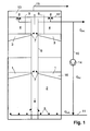
- the first gas separator is in the lower one Area of the reactor arranged, so in the sludge bed of the reactor. In the mud bed Much of the biochemical conversion of the organic material takes place. The A large part of the resulting biogas is captured by the first gas separator and directed into a central riser. The rest of the gas flows through the area above the sludge bed and is held in a second gas separator, which is over the mud bed and is also derived into the riser pipe. A little rest escapes on the water surface into the gas collection space above. Above The second gas separator has a sedimentation zone for the biomass.
- a part is separated by a gas separator arranged in the sludge bed of the reactor of the biogas is already removed from the system in the sludge bed, which makes it too high Empty gas pipe speeds can be avoided.
- the diameter of the riser pipe is dimensioned so that 5 to 25% of the cross-sectional area of the reactor is filled by the riser pipe. This will usually result in a Gas jack effect (mammoth pump effect) avoided.
- the gas separator elements are arranged radially to the riser pipe, because then the gas collected on the concave bottom of the gas separator element can flow along the gas separator element to the riser pipe. This can be done are supported that the gas separator elements are arranged obliquely to the horizontal are, that is, the end of the reactor wall is lower than that of the riser.
- the configuration according to which the riser pipe for each is also advantageous and simple Gas separator element has at least one gas transfer opening, of which the gas collected by the gas separator element can flow directly into the riser pipe. There are therefore no other devices, such as a drain pipe for each one Gas separator element is required to discharge the gas. This function is used alone fulfilled by the gas separator element and the gas transfer opening.
- any biomass carried into the riser can easily be in the riser themselves are conveyed downward by having openings through which Biomass from the riser pipe can sink into the reactor space.
- the carried Floating sludge is separated by a baffle at the top of the riser.
- the trigger devices located outside the baffle are opened this way kept free from swimming mud.
- the first gas separator is located in the lower half of the reactor 1, which consists of a layer of gas separator elements that collect enable the biogas formed and it towards the central riser 6 in which the biogas rises.
- a second gas separator 3 which also consists of a Location of gas separator elements.
- connection between the gas separator elements of the two gas separators 1, 3 and the straight, central riser pipe 6 form gas inlet openings 7, which are the transition enable the biogas into the riser pipe 6, so that the biogas into the gas collecting space 13 can rise. From there, the biogas is drawn off, as indicated by line 15.
- the second gas separator 3 on the reactor head By gas pre-separation in the sludge bed 2 through the first gas separator 1 and the sedimentation of the biomass, by the second gas separator 3 on the reactor head, preferably sludge pellets, in the sedimentation chamber 4 above the second gas separator 3 reached.
- Clear water drainage devices are located on the water surface 8, such as gutters.
- the central riser pipe 6 For the separation or retention of floating sludge of the extraction devices is the central riser pipe 6 with a baffle 9 surrounded.
- the baffle 9 is designed here as a tube that is concentric with the riser 6 is arranged outside the riser pipe, and extends from the second gas separator 3 to over the upper end of the riser pipe 6, which ends below the water surface 12 and further beyond the water surface into the gas collecting space 13.
- the riser pipe has openings 20 in the lower region near the bottom through which Biomass from the riser 6 can sink back into the reactor space.
- the riser pipe 6 extends to the bottom of the reactor, with the lower pipe end opposite the reactor is complete.
- the upper pipe end of the riser pipe is open.
- a recirculation from the outlet may be necessary to set defined inlet concentrations of the reactor via a pump 14 and a recirculation line 10 into the feed pipe 11 required.
- Fig. 2 is a cross section according to a horizontal sectional area between the second gas separator 3 and water surface 12 according to FIG. 1 and shows the arrangement of the gas separator elements 16 in the reactor, only three gas separator elements 16 being shown are.
- each gas separator 1, 3 is made of one layer of gas separator elements 16 formed, which overlap each other in partial areas and essentially the Cover the entire reactor cross section outside the riser pipe 6. Every gas separator element 16 covers a sector-shaped cross-sectional area which in this case is circular Reactor cross section and extends from the wall of the riser 6 to the reactor wall 17th
- Fig. 3 shows a gas separator element 16 in cross section looking towards the riser 6.
- the cross section of the gas separator element 16 is angular and asymmetrical formed by extending one leg 18 of the hood-shaped gas separator element is formed as the other leg 19.
- the cross section of the gas separator elements 16 increases in the radial direction in proportion to the distance from the riser pipe 6, so that - As shown in Fig. 2 - the reactor cross-section essentially by a layer of Gas separator elements 16 can be covered.
- the sludge pellets sedimented in the sedimentation room 4 slide along the tops of gas separator elements 16 and sink between the gas separator elements 16 down back into the mud bed.
Landscapes
- Life Sciences & Earth Sciences (AREA)
- Health & Medical Sciences (AREA)
- Engineering & Computer Science (AREA)
- Chemical & Material Sciences (AREA)
- Organic Chemistry (AREA)
- Zoology (AREA)
- Wood Science & Technology (AREA)
- Bioinformatics & Cheminformatics (AREA)
- Microbiology (AREA)
- Genetics & Genomics (AREA)
- Biochemistry (AREA)
- General Engineering & Computer Science (AREA)
- General Health & Medical Sciences (AREA)
- Sustainable Development (AREA)
- Biomedical Technology (AREA)
- Biotechnology (AREA)
- Molecular Biology (AREA)
- Water Supply & Treatment (AREA)
- Oil, Petroleum & Natural Gas (AREA)
- General Chemical & Material Sciences (AREA)
- Environmental & Geological Engineering (AREA)
- Hydrology & Water Resources (AREA)
- Biodiversity & Conservation Biology (AREA)
- Clinical Laboratory Science (AREA)
- Purification Treatments By Anaerobic Or Anaerobic And Aerobic Bacteria Or Animals (AREA)
Priority Applications (6)
| Application Number | Priority Date | Filing Date | Title |
|---|---|---|---|
| EP02022760A EP1408009B1 (fr) | 2002-10-11 | 2002-10-11 | Réacteur à deux séparateurs de gaz et procédé anaérobie de traitement de liquides |
| DE50204108T DE50204108D1 (de) | 2002-10-11 | 2002-10-11 | Reaktor mit zwei Gasabscheidern und Verfahren zur anaeroben Behandlung von Flüssigkeiten |
| AT02022760T ATE303348T1 (de) | 2002-10-11 | 2002-10-11 | Reaktor mit zwei gasabscheidern und verfahren zur anaeroben behandlung von flüssigkeiten |
| PCT/EP2003/010622 WO2004035486A1 (fr) | 2002-10-11 | 2003-09-24 | Reacteur a deux separateurs de gaz et procede de traitement anaerobie de liquides |
| AU2003271636A AU2003271636A1 (en) | 2002-10-11 | 2003-09-24 | Reactor with two gas traps and method for the anaerobic treatment of liquids |
| CNB038239744A CN1303011C (zh) | 2002-10-11 | 2003-09-24 | 具有两个气体分离器的反应器和用于厌氧处理液体的方法 |
Applications Claiming Priority (1)
| Application Number | Priority Date | Filing Date | Title |
|---|---|---|---|
| EP02022760A EP1408009B1 (fr) | 2002-10-11 | 2002-10-11 | Réacteur à deux séparateurs de gaz et procédé anaérobie de traitement de liquides |
Publications (2)
| Publication Number | Publication Date |
|---|---|
| EP1408009A1 true EP1408009A1 (fr) | 2004-04-14 |
| EP1408009B1 EP1408009B1 (fr) | 2005-08-31 |
Family
ID=32010960
Family Applications (1)
| Application Number | Title | Priority Date | Filing Date |
|---|---|---|---|
| EP02022760A Expired - Lifetime EP1408009B1 (fr) | 2002-10-11 | 2002-10-11 | Réacteur à deux séparateurs de gaz et procédé anaérobie de traitement de liquides |
Country Status (6)
| Country | Link |
|---|---|
| EP (1) | EP1408009B1 (fr) |
| CN (1) | CN1303011C (fr) |
| AT (1) | ATE303348T1 (fr) |
| AU (1) | AU2003271636A1 (fr) |
| DE (1) | DE50204108D1 (fr) |
| WO (1) | WO2004035486A1 (fr) |
Cited By (3)
| Publication number | Priority date | Publication date | Assignee | Title |
|---|---|---|---|---|
| JP2005342691A (ja) * | 2004-06-07 | 2005-12-15 | Able:Kk | メタン醗酵処理方法およびその装置 |
| WO2007058557A2 (fr) | 2005-11-18 | 2007-05-24 | Universidade Do Minho | Reacteur anaerobie pour extraire des acides gras a chaine longue d'eaux usees contenant des graisses |
| CN101781022A (zh) * | 2010-03-12 | 2010-07-21 | 浙江大学 | 气升式膨胀床厌氧生物反应器 |
Families Citing this family (6)
| Publication number | Priority date | Publication date | Assignee | Title |
|---|---|---|---|---|
| DE202006013811U1 (de) * | 2006-07-13 | 2007-11-22 | Meri Entsorgungstechnik für die Papierindustrie GmbH | Reaktor mit Zulaufverteilsystem zur anaeroben Abwasserreinigung |
| DE102006032489B4 (de) * | 2006-07-13 | 2008-06-26 | Meri Entsorgungstechnik für die Papierindustrie GmbH | Reaktor mit Zulaufverteilsystem zur anaeroben Abwasserreinigung |
| DE102008017020A1 (de) * | 2008-04-03 | 2009-10-08 | Wolfgang Eggert | Reaktor mit Dreiphasentrennvorrichtung |
| GB0921836D0 (en) * | 2009-12-14 | 2010-01-27 | Prebble Andrew | Anaerobic reactor |
| DE202011106472U1 (de) * | 2011-09-29 | 2013-01-08 | 4Biogas Gmbh & Co. Kg | Biogasreaktor mit einem Reaktorbehälter |
| CN102730827A (zh) * | 2012-06-11 | 2012-10-17 | 苏州顶裕水务科技有限公司 | 一种上流式厌氧污泥生化反应器 |
Citations (5)
| Publication number | Priority date | Publication date | Assignee | Title |
|---|---|---|---|---|
| JPS61174995A (ja) * | 1985-01-29 | 1986-08-06 | Nippon Beet Sugar Mfg Co Ltd | 嫌気性消化槽 |
| US4609460A (en) * | 1984-07-24 | 1986-09-02 | Paques B.V. | Anaerobic purification equipment for waste water |
| EP0300348A2 (fr) * | 1987-07-18 | 1989-01-25 | Herbert Prof. Dr.-Ing. Märkl | Réacteur pour le biogaz |
| DE4213015A1 (de) * | 1992-04-21 | 1993-10-28 | Maerkl Herbert | Biogasreaktor |
| EP0808805A1 (fr) * | 1996-05-22 | 1997-11-26 | CT Umwelttechnik AG | Procédé et réacteur pour la purification anaérobie des eaux usées dans un lit de boue |
-
2002
- 2002-10-11 DE DE50204108T patent/DE50204108D1/de not_active Expired - Lifetime
- 2002-10-11 AT AT02022760T patent/ATE303348T1/de active
- 2002-10-11 EP EP02022760A patent/EP1408009B1/fr not_active Expired - Lifetime
-
2003
- 2003-09-24 CN CNB038239744A patent/CN1303011C/zh not_active Expired - Fee Related
- 2003-09-24 WO PCT/EP2003/010622 patent/WO2004035486A1/fr not_active Ceased
- 2003-09-24 AU AU2003271636A patent/AU2003271636A1/en not_active Abandoned
Patent Citations (5)
| Publication number | Priority date | Publication date | Assignee | Title |
|---|---|---|---|---|
| US4609460A (en) * | 1984-07-24 | 1986-09-02 | Paques B.V. | Anaerobic purification equipment for waste water |
| JPS61174995A (ja) * | 1985-01-29 | 1986-08-06 | Nippon Beet Sugar Mfg Co Ltd | 嫌気性消化槽 |
| EP0300348A2 (fr) * | 1987-07-18 | 1989-01-25 | Herbert Prof. Dr.-Ing. Märkl | Réacteur pour le biogaz |
| DE4213015A1 (de) * | 1992-04-21 | 1993-10-28 | Maerkl Herbert | Biogasreaktor |
| EP0808805A1 (fr) * | 1996-05-22 | 1997-11-26 | CT Umwelttechnik AG | Procédé et réacteur pour la purification anaérobie des eaux usées dans un lit de boue |
Non-Patent Citations (1)
| Title |
|---|
| PATENT ABSTRACTS OF JAPAN vol. 010, no. 383 (C - 393) 23 December 1986 (1986-12-23) * |
Cited By (4)
| Publication number | Priority date | Publication date | Assignee | Title |
|---|---|---|---|---|
| JP2005342691A (ja) * | 2004-06-07 | 2005-12-15 | Able:Kk | メタン醗酵処理方法およびその装置 |
| WO2007058557A2 (fr) | 2005-11-18 | 2007-05-24 | Universidade Do Minho | Reacteur anaerobie pour extraire des acides gras a chaine longue d'eaux usees contenant des graisses |
| CN101781022A (zh) * | 2010-03-12 | 2010-07-21 | 浙江大学 | 气升式膨胀床厌氧生物反应器 |
| CN101781022B (zh) * | 2010-03-12 | 2011-06-29 | 浙江大学 | 气升式膨胀床厌氧生物反应器 |
Also Published As
| Publication number | Publication date |
|---|---|
| WO2004035486A1 (fr) | 2004-04-29 |
| EP1408009B1 (fr) | 2005-08-31 |
| ATE303348T1 (de) | 2005-09-15 |
| AU2003271636A1 (en) | 2004-05-04 |
| CN1303011C (zh) | 2007-03-07 |
| CN1688512A (zh) | 2005-10-26 |
| DE50204108D1 (de) | 2005-10-06 |
Similar Documents
| Publication | Publication Date | Title |
|---|---|---|
| DD237158A5 (de) | Reaktor zur anoeroben reinigung von schmutzwasser | |
| EP1408008B1 (fr) | Réacteur avec un dispositif de séparation à trois phases et procédé de séparation à trois phases | |
| EP1408009B1 (fr) | Réacteur à deux séparateurs de gaz et procédé anaérobie de traitement de liquides | |
| EP0193969B1 (fr) | Réacteur en colonne à lit fixe pour les procédés de digestion anaérobie | |
| DE10314933B4 (de) | Vorrichtung zum Reinigen von Abwasser | |
| WO2011020651A1 (fr) | Réacteur de purification anaérobie d'eaux usées comprenant des dispositifs de séparation de phases multiples | |
| CH678722A5 (fr) | ||
| EP0530672A1 (fr) | Filtre lavable | |
| EP0125235A1 (fr) | Procédé et dispositif pour la purification biologique d'eau usée | |
| EP1943194B1 (fr) | Procede et reacteur pour traitement anaerobique d'eaux usees au moyen d un uasb | |
| WO2009121617A1 (fr) | Réacteur pour le traitement anaérobie des eaux usées | |
| DE202006013811U1 (de) | Reaktor mit Zulaufverteilsystem zur anaeroben Abwasserreinigung | |
| EP2260007B1 (fr) | Réacteur avec dispositif de séparation à trois phases | |
| DE3326879A1 (de) | Biogasreaktor | |
| DE2005052C3 (de) | Vorrichtung zum Abfuhren von Abwasser aus einem Belüftungsbecken | |
| EP2016030B1 (fr) | Réacteur pour l'épuration anaérobie d'eaux usées | |
| EP2218688B1 (fr) | Procédé et dispositif de nettoyage anaérobie d'eau usée | |
| EP1657222B1 (fr) | Méthode et dispositif de traitement biologique d'une suspension dans un bioréacteur. | |
| DE3306149C2 (de) | Vorrichtung zur anaeroben Behandlung von Abwässern | |
| DE202004010707U1 (de) | Vorrichtung zur gleichzeitigen Behandlung von Abwässern und organischen Reststoffen | |
| DE3324072C2 (de) | Vorrichtung zur anaeroben Abwasserreinigung | |
| DE19842884C9 (de) | Verfahren zur biologischen und biologisch-chemischen aufbereitung von abwasser mit integriertem schlammabscheider | |
| EP1852399A2 (fr) | station d'épuration d'eau compacte, procédé de traitement des eaux usées | |
| DE10335961B4 (de) | Vorrichtung und Verfahren zur anaeroben Reinigung von Abwasser | |
| DE19842884C2 (de) | Verfahren zur biologischen und biologisch-chemischen Aufbereitung von Abwasser mit integriertem Schlammabscheider |
Legal Events
| Date | Code | Title | Description |
|---|---|---|---|
| PUAI | Public reference made under article 153(3) epc to a published international application that has entered the european phase |
Free format text: ORIGINAL CODE: 0009012 |
|
| 17P | Request for examination filed |
Effective date: 20030721 |
|
| AK | Designated contracting states |
Kind code of ref document: A1 Designated state(s): AT BE BG CH CY CZ DE DK EE ES FI FR GB GR IE IT LI LU MC NL PT SE SK TR |
|
| AX | Request for extension of the european patent |
Extension state: AL LT LV MK RO SI |
|
| AKX | Designation fees paid |
Designated state(s): AT BE BG CH CY CZ DE DK EE ES FI FR GB GR IE IT LI LU MC NL PT SE SK TR |
|
| AXX | Extension fees paid |
Extension state: RO Payment date: 20040719 Extension state: SI Payment date: 20040719 |
|
| GRAP | Despatch of communication of intention to grant a patent |
Free format text: ORIGINAL CODE: EPIDOSNIGR1 |
|
| GRAS | Grant fee paid |
Free format text: ORIGINAL CODE: EPIDOSNIGR3 |
|
| RAP1 | Party data changed (applicant data changed or rights of an application transferred) |
Owner name: VA TECH WABAG GMBH |
|
| GRAA | (expected) grant |
Free format text: ORIGINAL CODE: 0009210 |
|
| AK | Designated contracting states |
Kind code of ref document: B1 Designated state(s): AT BE BG CH CY CZ DE DK EE ES FI FR GB GR IE IT LI LU MC NL PT SE SK TR |
|
| AX | Request for extension of the european patent |
Extension state: RO SI |
|
| PG25 | Lapsed in a contracting state [announced via postgrant information from national office to epo] |
Ref country code: IE Free format text: LAPSE BECAUSE OF FAILURE TO SUBMIT A TRANSLATION OF THE DESCRIPTION OR TO PAY THE FEE WITHIN THE PRESCRIBED TIME-LIMIT Effective date: 20050831 Ref country code: FI Free format text: LAPSE BECAUSE OF FAILURE TO SUBMIT A TRANSLATION OF THE DESCRIPTION OR TO PAY THE FEE WITHIN THE PRESCRIBED TIME-LIMIT Effective date: 20050831 Ref country code: GB Free format text: LAPSE BECAUSE OF FAILURE TO SUBMIT A TRANSLATION OF THE DESCRIPTION OR TO PAY THE FEE WITHIN THE PRESCRIBED TIME-LIMIT Effective date: 20050831 Ref country code: EE Free format text: LAPSE BECAUSE OF FAILURE TO SUBMIT A TRANSLATION OF THE DESCRIPTION OR TO PAY THE FEE WITHIN THE PRESCRIBED TIME-LIMIT Effective date: 20050831 Ref country code: NL Free format text: LAPSE BECAUSE OF FAILURE TO SUBMIT A TRANSLATION OF THE DESCRIPTION OR TO PAY THE FEE WITHIN THE PRESCRIBED TIME-LIMIT Effective date: 20050831 Ref country code: ES Free format text: LAPSE BECAUSE OF FAILURE TO SUBMIT A TRANSLATION OF THE DESCRIPTION OR TO PAY THE FEE WITHIN THE PRESCRIBED TIME-LIMIT Effective date: 20050831 Ref country code: SK Free format text: LAPSE BECAUSE OF FAILURE TO SUBMIT A TRANSLATION OF THE DESCRIPTION OR TO PAY THE FEE WITHIN THE PRESCRIBED TIME-LIMIT Effective date: 20050831 Ref country code: CZ Free format text: LAPSE BECAUSE OF FAILURE TO SUBMIT A TRANSLATION OF THE DESCRIPTION OR TO PAY THE FEE WITHIN THE PRESCRIBED TIME-LIMIT Effective date: 20050831 Ref country code: TR Free format text: LAPSE BECAUSE OF FAILURE TO SUBMIT A TRANSLATION OF THE DESCRIPTION OR TO PAY THE FEE WITHIN THE PRESCRIBED TIME-LIMIT Effective date: 20050831 Ref country code: IT Free format text: LAPSE BECAUSE OF FAILURE TO SUBMIT A TRANSLATION OF THE DESCRIPTION OR TO PAY THE FEE WITHIN THE PRESCRIBED TIME-LIMIT;WARNING: LAPSES OF ITALIAN PATENTS WITH EFFECTIVE DATE BEFORE 2007 MAY HAVE OCCURRED AT ANY TIME BEFORE 2007. THE CORRECT EFFECTIVE DATE MAY BE DIFFERENT FROM THE ONE RECORDED. Effective date: 20050831 |
|
| REG | Reference to a national code |
Ref country code: GB Ref legal event code: FG4D Free format text: NOT ENGLISH Ref country code: CH Ref legal event code: EP |
|
| REG | Reference to a national code |
Ref country code: IE Ref legal event code: FG4D Free format text: LANGUAGE OF EP DOCUMENT: GERMAN |
|
| REF | Corresponds to: |
Ref document number: 50204108 Country of ref document: DE Date of ref document: 20051006 Kind code of ref document: P |
|
| PG25 | Lapsed in a contracting state [announced via postgrant information from national office to epo] |
Ref country code: CY Free format text: LAPSE BECAUSE OF FAILURE TO SUBMIT A TRANSLATION OF THE DESCRIPTION OR TO PAY THE FEE WITHIN THE PRESCRIBED TIME-LIMIT Effective date: 20051011 |
|
| PG25 | Lapsed in a contracting state [announced via postgrant information from national office to epo] |
Ref country code: MC Free format text: LAPSE BECAUSE OF NON-PAYMENT OF DUE FEES Effective date: 20051031 Ref country code: BE Free format text: LAPSE BECAUSE OF NON-PAYMENT OF DUE FEES Effective date: 20051031 Ref country code: LU Free format text: LAPSE BECAUSE OF NON-PAYMENT OF DUE FEES Effective date: 20051031 |
|
| PG25 | Lapsed in a contracting state [announced via postgrant information from national office to epo] |
Ref country code: GR Free format text: LAPSE BECAUSE OF FAILURE TO SUBMIT A TRANSLATION OF THE DESCRIPTION OR TO PAY THE FEE WITHIN THE PRESCRIBED TIME-LIMIT Effective date: 20051130 Ref country code: SE Free format text: LAPSE BECAUSE OF FAILURE TO SUBMIT A TRANSLATION OF THE DESCRIPTION OR TO PAY THE FEE WITHIN THE PRESCRIBED TIME-LIMIT Effective date: 20051130 Ref country code: BG Free format text: LAPSE BECAUSE OF FAILURE TO SUBMIT A TRANSLATION OF THE DESCRIPTION OR TO PAY THE FEE WITHIN THE PRESCRIBED TIME-LIMIT Effective date: 20051130 Ref country code: DK Free format text: LAPSE BECAUSE OF FAILURE TO SUBMIT A TRANSLATION OF THE DESCRIPTION OR TO PAY THE FEE WITHIN THE PRESCRIBED TIME-LIMIT Effective date: 20051130 |
|
| PG25 | Lapsed in a contracting state [announced via postgrant information from national office to epo] |
Ref country code: PT Free format text: LAPSE BECAUSE OF FAILURE TO SUBMIT A TRANSLATION OF THE DESCRIPTION OR TO PAY THE FEE WITHIN THE PRESCRIBED TIME-LIMIT Effective date: 20060222 |
|
| NLV1 | Nl: lapsed or annulled due to failure to fulfill the requirements of art. 29p and 29m of the patents act | ||
| REG | Reference to a national code |
Ref country code: IE Ref legal event code: FD4D |
|
| GBV | Gb: ep patent (uk) treated as always having been void in accordance with gb section 77(7)/1977 [no translation filed] |
Effective date: 20050831 |
|
| PLBE | No opposition filed within time limit |
Free format text: ORIGINAL CODE: 0009261 |
|
| STAA | Information on the status of an ep patent application or granted ep patent |
Free format text: STATUS: NO OPPOSITION FILED WITHIN TIME LIMIT |
|
| 26N | No opposition filed |
Effective date: 20060601 |
|
| EN | Fr: translation not filed | ||
| PG25 | Lapsed in a contracting state [announced via postgrant information from national office to epo] |
Ref country code: FR Free format text: LAPSE BECAUSE OF FAILURE TO SUBMIT A TRANSLATION OF THE DESCRIPTION OR TO PAY THE FEE WITHIN THE PRESCRIBED TIME-LIMIT Effective date: 20061027 |
|
| BERE | Be: lapsed |
Owner name: VA TECH WABAG GMBH Effective date: 20051031 |
|
| PG25 | Lapsed in a contracting state [announced via postgrant information from national office to epo] |
Ref country code: FR Free format text: LAPSE BECAUSE OF FAILURE TO SUBMIT A TRANSLATION OF THE DESCRIPTION OR TO PAY THE FEE WITHIN THE PRESCRIBED TIME-LIMIT Effective date: 20051031 |
|
| PG25 | Lapsed in a contracting state [announced via postgrant information from national office to epo] |
Ref country code: FR Free format text: LAPSE BECAUSE OF FAILURE TO SUBMIT A TRANSLATION OF THE DESCRIPTION OR TO PAY THE FEE WITHIN THE PRESCRIBED TIME-LIMIT Effective date: 20050831 |
|
| PGFP | Annual fee paid to national office [announced via postgrant information from national office to epo] |
Ref country code: AT Payment date: 20101021 Year of fee payment: 9 |
|
| PGFP | Annual fee paid to national office [announced via postgrant information from national office to epo] |
Ref country code: CH Payment date: 20101029 Year of fee payment: 9 |
|
| PGFP | Annual fee paid to national office [announced via postgrant information from national office to epo] |
Ref country code: DE Payment date: 20101227 Year of fee payment: 9 |
|
| REG | Reference to a national code |
Ref country code: CH Ref legal event code: PL |
|
| PG25 | Lapsed in a contracting state [announced via postgrant information from national office to epo] |
Ref country code: LI Free format text: LAPSE BECAUSE OF NON-PAYMENT OF DUE FEES Effective date: 20111031 Ref country code: DE Free format text: LAPSE BECAUSE OF NON-PAYMENT OF DUE FEES Effective date: 20120501 Ref country code: CH Free format text: LAPSE BECAUSE OF NON-PAYMENT OF DUE FEES Effective date: 20111031 |
|
| REG | Reference to a national code |
Ref country code: DE Ref legal event code: R119 Ref document number: 50204108 Country of ref document: DE Effective date: 20120501 |
|
| REG | Reference to a national code |
Ref country code: AT Ref legal event code: MM01 Ref document number: 303348 Country of ref document: AT Kind code of ref document: T Effective date: 20111011 |
|
| PG25 | Lapsed in a contracting state [announced via postgrant information from national office to epo] |
Ref country code: AT Free format text: LAPSE BECAUSE OF NON-PAYMENT OF DUE FEES Effective date: 20111011 |