EP0300538A1 - Vorrichtung zur positiven Befestigung einer Radzierblende an einer Kraftfahrzeugradfelge - Google Patents
Vorrichtung zur positiven Befestigung einer Radzierblende an einer Kraftfahrzeugradfelge Download PDFInfo
- Publication number
- EP0300538A1 EP0300538A1 EP88201399A EP88201399A EP0300538A1 EP 0300538 A1 EP0300538 A1 EP 0300538A1 EP 88201399 A EP88201399 A EP 88201399A EP 88201399 A EP88201399 A EP 88201399A EP 0300538 A1 EP0300538 A1 EP 0300538A1
- Authority
- EP
- European Patent Office
- Prior art keywords
- edge
- hubcap
- wheel
- fixing
- rim
- Prior art date
- Legal status (The legal status is an assumption and is not a legal conclusion. Google has not performed a legal analysis and makes no representation as to the accuracy of the status listed.)
- Granted
Links
- 230000037431 insertion Effects 0.000 claims description 4
- 238000003780 insertion Methods 0.000 claims description 4
- 210000005069 ears Anatomy 0.000 claims description 3
- 230000000694 effects Effects 0.000 claims description 2
- 230000002093 peripheral effect Effects 0.000 description 4
- 238000009434 installation Methods 0.000 description 2
- 230000002452 interceptive effect Effects 0.000 description 2
- 238000004519 manufacturing process Methods 0.000 description 2
- 239000000463 material Substances 0.000 description 2
- WTEVQBCEXWBHNA-YFHOEESVSA-N neral Chemical compound CC(C)=CCC\C(C)=C/C=O WTEVQBCEXWBHNA-YFHOEESVSA-N 0.000 description 2
- WTEVQBCEXWBHNA-UHFFFAOYSA-N Citral Natural products CC(C)=CCCC(C)=CC=O WTEVQBCEXWBHNA-UHFFFAOYSA-N 0.000 description 1
- 241001080024 Telles Species 0.000 description 1
- 230000001133 acceleration Effects 0.000 description 1
- WTEVQBCEXWBHNA-JXMROGBWSA-N citral A Natural products CC(C)=CCC\C(C)=C\C=O WTEVQBCEXWBHNA-JXMROGBWSA-N 0.000 description 1
- 238000001816 cooling Methods 0.000 description 1
- 238000006073 displacement reaction Methods 0.000 description 1
- 239000002184 metal Substances 0.000 description 1
- 238000009828 non-uniform distribution Methods 0.000 description 1
- 210000000056 organ Anatomy 0.000 description 1
- 230000001681 protective effect Effects 0.000 description 1
- 239000002966 varnish Substances 0.000 description 1
Images

Classifications
-
- B—PERFORMING OPERATIONS; TRANSPORTING
- B60—VEHICLES IN GENERAL
- B60B—VEHICLE WHEELS; CASTORS; AXLES FOR WHEELS OR CASTORS; INCREASING WHEEL ADHESION
- B60B7/00—Wheel cover discs, rings, or the like, for ornamenting, protecting, venting, or obscuring, wholly or in part, the wheel body, rim, hub, or tyre sidewall, e.g. wheel cover discs, wheel cover discs with cooling fins
- B60B7/06—Fastening arrangements therefor
- B60B7/14—Fastening arrangements therefor comprising screw-threaded means
Definitions
- the present invention relates to a fixing system applied to an embellishing disc for a vehicle wheel, in order to effect positive fixing to the rim of a wheel, this rim ending externally with a concave edge in a channel.
- the hubcaps can be applied to the wheels by elastic snap fasteners arranged so as to engage undercuts presented by the rims of the wheels, but in other cases, especially for heavy vehicles, generally industrial vehicles, it is required that the fixing of the hubcaps on the wheels is positive. In these cases, recourse is usually made to special stirrups which are tightened under the wheel fixing bolts and which are provided with means for receiving, in turn, the fixing of the hubcaps.
- the object of the present invention is to rationalize the positive fixing devices for the wheel cover discs, so as to overcome these drawbacks, and more particularly to obtain that a cover disc can be applied and fixed positively to any wheel having the diameter. for which the hubcap is intended, regardless of configuration of the fixing means of the wheel itself and, in any case, without in any way interfering with these fixing means.
- the fixing system applied to a hubcap disc comprises at least three connection devices, arranged along the periphery of the hubcap to engage the concave channel edge of the rim , and that at least one of these connection devices is mobile and comprises an engagement member which can be moved between a mounting position, in which it can be threaded inside said channeled edge to allow mounting of the hubcap on the wheel, and a fixing position, in which it engages said channel edge to positively fix the hubcap to it.
- the cover disc previously arranged with its mobile connection devices in the mounting configuration, can be applied to a wheel by threading the engagement devices of the connection devices inside the channel edge, after whereby the latter can be maneuvered so as to move their mounting members from the mounting position to the fixing position, which then engage the concave edge in the channel of the wheel, thus completing the positive fixing of the hubcap.
- the fixing devices for the hubcap have no relation to the means for fixing the wheel, the configuration of which is therefore indifferent, and a hubcap provided with the fixing system according to the invention can be applied to any wheel having the diameter for which the hubcap is projected, provided that this wheel shows said channel edge as, on the other hand, is usually in general for the wheels currently manufactured, intended for industrial vehicles.
- a part of said hubcap connection devices is of the fixed type, and these fixed connection devices are arranged in correspondence with one half of the periphery of the hubcap, so that they can be engaged by simple insertion into the concave channel edge by which the rim of the wheel ends externally, and said mobile connection devices are located symmetrically on the side of the periphery of the hubcap opposite to said fixed connection devices.
- said fixed connection devices are preferably in number of three or four, and said mobile connection devices are preferably in number of two.
- connection devices are of the mobile type.
- the mobile connection devices must be at least three in number, and preferably there are four.
- the hubcap shown is provided with a peripheral edge 1, intended to be affixed against the rim of a wheel, a projecting strip 2 and a disc 3 having a central region 4 which is usually intended to receive a mark or an ornament.
- a number of openings, respectively 5 and 6, which in addition to having an aesthetic reason ensure the cooling of the braking system of the wheel.
- the fixing system according to the invention relates only to the peripheral edge 1 of the hubcap, and therefore the conformation of all the other parts of the hubcap is completely free and can be drawn arbitrarily, either in a aesthetic purpose only for technical reasons. It should therefore be understood that the representation of a particular form of hubcap has only a demonstration purpose, but that the invention can be applied to hubcaps having in general any conformation.
- the fastening system comprises, in this case, four fixed connection devices, indicated generally by 10, and two mobile connection devices, indicated generally by 20.
- Two fixed connection devices 10 are arranged diametrically opposite, and the others two are distributed at 60 ° reciprocal angular distance between the first two, thus occupying half of the periphery of the wheel.
- each of these devices has a projection intended to engage, by simple insertion, a concave edge in a channel presented by the rim of the wheel to which the hubcap is to be applied.
- theoretically such an insertion would not be geometrically possible for two diametrically opposite connection devices 10, but indeed it can be carried out in general.
- the mobile connection devices 20 are, in this case, in number of two, and they are arranged at 60 ° angular distance between the fixed connection devices 10 diametrically opposite, so that the hubcap is provided in total with six devices of connection, uniformly distributed along its periphery.
- this particularly rational arrangement is not essential, and that non-uniform distributions can also be adopted, as well as different numbers of connection devices.
- each fixed connection device 10 is constituted by a body 11, which can be molded in plastic, showing a projection 12 capable of engaging the peripheral edge 1 (folded inwards on the back) of the hubcap, and a hole 13 in which a screw-tap 19 can be screwed for fixing the connection device 10 to the hubcap.
- the edge 1 of the hubcap has, in correspondence with each position in which a fixed connection device 10 is to be mounted, a flared hole 7.
- the fixed connection device 10 also shows a protective projection 14, arranged behind the projection 12 and intended to bear against the rim of the wheel to which the hubcap is applied, and another projection 15 which is intended to be inserted in the concave edge in channel C by which ends externally the rim of the wheel.
- each fixed connection device 10 is capable of effecting a stable fixing and positive of the corresponding part of the periphery of the hubcap, when it has been inserted into the edge in channel C.
- the means 12, 13 and 19 for fixing the fixed connection device 10 to the edge 1 of the hubcap could also be produced in different shapes, which could possibly not require that the edge 1 of the hubcap is folded inwards on the back.
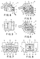
- Each mobile connection device 20 (FIGS. 5 to 8) comprises a support member 21 and an engagement member 31.
- the support member 21 can be molded from plastic, and it is provided with a projection 22 capable of insert into the peripheral edge 1 folded inwards at the back of the hubcap, and two holes 23 in which one can screw screws to fix the device 20 to the edge 1 of the hubcap by passing through similar holes holes 7, presented by the edge itself.
- the support member 21 further shows protection and engagement projections 24, disposed behind the projection 22 and intended to bear against the rim of the wheel by hooking its periphery, and two ears 26 in which is mounted a stud 29 supporting the movable engagement member 31.
- the support member 21 shows two seats for springs which will be said later, and a seat 27 for a traction screw 28, which can be operated through an opening 8 made, in correspondence with each mobile connection device 20, in the edge 1 of the hubcap.
- the engagement member 31 which can also be made of plastic, shows two ears 26 by which it is pivoted on the stud 29.
- the body of the member 31 contains a metal nut 38, into which the traction screw 28, and it is extended by forming a projection 35 capable of engaging the concave edge in channel C of the wheel.
- the projection 35 is arranged in a position such as to allow its passage inside the concave edge C Therefore, when all mobile connection devices are are in this condition and the fixed connection devices 10 have been inserted into the edge in channel C, the hubcap can be affixed against the rim in its installation position.
- the traction screw 28 is maneuvered by screwing it into the threaded hole of the nut 38, and then the engagement member 31 is pulled towards the support member 21 in rotating around the stud 29, and the projection 35 is close to the edge in channel C until it engages under pressure, as shown in FIG. 6.
- the hubcap is positively attached to the rim of the wheel. It is obvious that, by opposite maneuvers, the hubcap can be removed from the wheel in an equally easy manner.
- the means for fixing the support member 21 to the edge 1 of the hubcap can be modified compared to those indicated by way of example, and the shape of the projection 35 can be conveniently chosen in relation to the shape of the concave edge C in channel of the type of wheel for which the hubcap is intended.
- the use of a traction screw 28 screwing into a nut 28 is a particularly practical means for controlling the passage of the engagement member from the mounting position to the fixing position and vice versa, but, well of course, also different means could be used for this purpose.
- the total number of fixed 10 and mobile connection devices 20, as already said, can be modified according to the different requirements which arise; in any case, for effective fixing, a total of at least three connection devices must be provided, including at least one mobile fixing device of type 20. Preferably, however, use is made of three or four fixed connections 10 and two mobile connection devices 20.
- connection devices 10 are more economical than the mobile connection devices 20, and it is this reason which may suggest adopting connection devices of these two different types.
- the connection devices, all of the mobile type must be at least three in number. But preferably there are four of them.
- a screw 33 provided with a conical tip 34 which protrudes from the surface of the projection 35 towards the edge C in channel of the rim of the wheel.
- This point 34 is inserted slightly into the material of the edge C in the channel, or at least into its varnish, when the mobile connection devices 20 are moved into the fixing position, as shown in FIG. 6 in which, however, the size of this depression is exaggerated to make the representation clearer. In this way a particularly effective solidarity is obtained between the hubcap and the wheel and, in particular, any angular displacement of the hubcap caused by the accelerations and decelerations of the wheel is prevented.
- two springs 37 are arranged in seats of the body 21, located on both sides of the traction screw 28. These springs, which are compressed by the engagement member 31 in its fixing position, then push said engagement member towards the mounting position, which facilitates the release of the hub cap when the traction screws 28 are unscrewed.
Landscapes
- Engineering & Computer Science (AREA)
- Mechanical Engineering (AREA)
- Connection Of Plates (AREA)
Applications Claiming Priority (2)
| Application Number | Priority Date | Filing Date | Title |
|---|---|---|---|
| IT8767641A IT1211233B (it) | 1987-07-23 | 1987-07-23 | Sistema di fissaggio positivo al cerchione della ruota per una coppa copriruota di veicolo industriale |
| IT6764187 | 1987-07-23 |
Publications (2)
| Publication Number | Publication Date |
|---|---|
| EP0300538A1 true EP0300538A1 (de) | 1989-01-25 |
| EP0300538B1 EP0300538B1 (de) | 1991-12-04 |
Family
ID=11304138
Family Applications (1)
| Application Number | Title | Priority Date | Filing Date |
|---|---|---|---|
| EP88201399A Expired - Lifetime EP0300538B1 (de) | 1987-07-23 | 1988-07-05 | Vorrichtung zur positiven Befestigung einer Radzierblende an einer Kraftfahrzeugradfelge |
Country Status (5)
| Country | Link |
|---|---|
| US (1) | US4889394A (de) |
| EP (1) | EP0300538B1 (de) |
| DE (1) | DE3866622D1 (de) |
| ES (1) | ES2028258T3 (de) |
| IT (1) | IT1211233B (de) |
Cited By (2)
| Publication number | Priority date | Publication date | Assignee | Title |
|---|---|---|---|---|
| US10703132B2 (en) | 2017-09-22 | 2020-07-07 | Consolidated Metco, Inc. | Wheel cover |
| US11667151B2 (en) | 2019-03-01 | 2023-06-06 | Consolidated Metco, Inc. | Wheel cover |
Families Citing this family (33)
| Publication number | Priority date | Publication date | Assignee | Title |
|---|---|---|---|---|
| USRE35497E (en) * | 1990-03-20 | 1997-04-29 | George A. Carter, III | Decorative simulated wheel cover retention system |
| US5046784A (en) * | 1990-03-20 | 1991-09-10 | Carter Iii George A | Wheel cover retention system |
| US5188428A (en) * | 1990-03-20 | 1993-02-23 | Carter Iii George A | Decorative simulated wheel cover retention system |
| US5135289A (en) * | 1990-08-27 | 1992-08-04 | Aero De Fleck, Ltd. | Wheel cover assembly |
| US5531508A (en) * | 1995-04-19 | 1996-07-02 | Bell, Iii; Randall R. | Heavy construction equipment tire guard |
| JP3598169B2 (ja) * | 1996-03-18 | 2004-12-08 | 株式会社東海理化電機製作所 | 自動車用ホイールカバー及びその取付クリップ |
| NL1018622C1 (nl) | 2001-07-24 | 2002-08-27 | Paul Johan Willem Mari Nooijen | Bevestigingsklem voor wieldop. |
| GB2433057A (en) * | 2005-12-06 | 2007-06-13 | Leo Nithas Frank Fynn | Protector for an alloy wheel |
| US7374248B1 (en) * | 2006-02-28 | 2008-05-20 | Clayton Anthony J | Rim covering device |
| US7775604B2 (en) * | 2008-05-13 | 2010-08-17 | Chen-Chun Chen | Interlocking method and its structure for wheel-rim cover |
| TWM355834U (en) * | 2008-12-16 | 2009-05-01 | zhen-jun Chen | Rim cover fastening structure |
| US8814253B1 (en) | 2011-04-21 | 2014-08-26 | Flowbelow, LLC | Aerodynamic quarter fender assembly and construction method |
| CN103813909A (zh) * | 2011-08-31 | 2014-05-21 | 凯迪拉克汽车公司 | 车轮罩 |
| EP4008610A3 (de) | 2012-11-01 | 2022-07-13 | Flowbelow Aero, Inc. | Aerodynamisches system und anpassbare verkleidung |
| US9694910B2 (en) | 2013-02-22 | 2017-07-04 | World View Enterprises Inc. | Near-space operation systems |
| US9365074B2 (en) | 2013-03-15 | 2016-06-14 | RealWheels Corporation | Wheel cover assembly and method of mounting |
| USD752494S1 (en) | 2013-03-15 | 2016-03-29 | RealWheels Corporation | Aerodynamic wheel cover |
| US9561687B2 (en) | 2013-03-21 | 2017-02-07 | RealWheels Corporation | Aerodynamic wheel cover assembly and method of mounting |
| USD744923S1 (en) | 2013-03-21 | 2015-12-08 | RealWheels Corporation | Aerodynamic wheel cover |
| USD739334S1 (en) * | 2013-10-18 | 2015-09-22 | World View Enterprises, Inc. | Capsule window |
| US9687037B1 (en) | 2014-02-06 | 2017-06-27 | Virginia Commonwealth University | Magnetic football helmet to reduce concussion injuries |
| US10787268B2 (en) | 2015-03-09 | 2020-09-29 | World View Enterprises Inc. | Rigidized assisted opening system for high altitude parafoils |
| US9540091B1 (en) | 2016-02-11 | 2017-01-10 | World View Enterprises Inc. | High altitude balloon systems and methods |
| US11932060B2 (en) | 2016-11-04 | 2024-03-19 | FlowBelow Aero, Inc. | Chassis mounted energy extraction and delivery system |
| US10124875B1 (en) | 2017-01-09 | 2018-11-13 | World View Enterprises Inc. | Continuous multi-chamber super pressure balloon |
| US10336432B1 (en) | 2017-01-09 | 2019-07-02 | World View Enterprises Inc. | Lighter than air balloon systems and methods |
| US10654529B2 (en) | 2017-06-24 | 2020-05-19 | FlowBelow Aero, Inc. | Aerodynamic systems and fairings with fairing caps |
| EP3652023A4 (de) | 2017-07-12 | 2021-04-07 | Flowbelow Aero, Inc. | Aerodynamische werkzeugkiste |
| US10882571B2 (en) | 2017-07-30 | 2021-01-05 | FlowBelow Aero, Inc. | Rotatable aerodynamic fairing system |
| US11072377B2 (en) | 2018-09-04 | 2021-07-27 | Lund, Inc. | Removable fairing |
| FR3114771B1 (fr) * | 2020-10-05 | 2022-10-14 | Hutchinson | Dispositif de fixation d’équipement sur jante |
| US11767064B2 (en) | 2021-01-12 | 2023-09-26 | FlowBelow Aero, Inc. | Spring-biased mud flap hanger with improved pivoting motion guidance |
| CA3214677A1 (en) * | 2021-04-08 | 2022-10-13 | Pradeep SHINDE | Apparatus, method and system for balloon altitude control by in-situ characterization and active energy management |
Citations (4)
| Publication number | Priority date | Publication date | Assignee | Title |
|---|---|---|---|---|
| DE7632702U1 (de) * | Kronprinz Ag, 5650 Solingen | |||
| US2631895A (en) * | 1949-05-20 | 1953-03-17 | Motor Wheel Corp | Cover for vehicle wheels |
| FR2166017A1 (de) * | 1971-12-27 | 1973-08-10 | Foster Edwin | |
| DE2629291A1 (de) * | 1976-06-30 | 1978-01-05 | Schirm Metallguss Gmbh & Co Kg | Rad fuer personenkraftwagen |
Family Cites Families (5)
| Publication number | Priority date | Publication date | Assignee | Title |
|---|---|---|---|---|
| FR735077A (fr) * | 1931-07-11 | 1932-11-03 | Dispositif anti-vol pour roue de secours | |
| US1937295A (en) * | 1933-01-03 | 1933-11-28 | Napier Co | Bottle lock |
| DE2451071C3 (de) * | 1974-10-26 | 1978-04-13 | Gebr. Happich Gmbh, 5600 Wuppertal | Schaumstoffkörper mit Befestigungsausbildungen |
| FR2418718A1 (fr) * | 1978-03-03 | 1979-09-28 | Peugeot Aciers Et Outillage | Enjoliveur de roue de vehicule et son dispositif de fixation |
| DE3314493C2 (de) * | 1983-04-21 | 1985-03-07 | Dr. Franz Schneider GmbH Kunststoffwerk, 8640 Kronach | Befestigungsanordnung für eine Radkappe |
-
1987
- 1987-07-23 IT IT8767641A patent/IT1211233B/it active
-
1988
- 1988-07-01 US US07/222,512 patent/US4889394A/en not_active Expired - Fee Related
- 1988-07-05 DE DE8888201399T patent/DE3866622D1/de not_active Expired - Fee Related
- 1988-07-05 ES ES198888201399T patent/ES2028258T3/es not_active Expired - Lifetime
- 1988-07-05 EP EP88201399A patent/EP0300538B1/de not_active Expired - Lifetime
Patent Citations (4)
| Publication number | Priority date | Publication date | Assignee | Title |
|---|---|---|---|---|
| DE7632702U1 (de) * | Kronprinz Ag, 5650 Solingen | |||
| US2631895A (en) * | 1949-05-20 | 1953-03-17 | Motor Wheel Corp | Cover for vehicle wheels |
| FR2166017A1 (de) * | 1971-12-27 | 1973-08-10 | Foster Edwin | |
| DE2629291A1 (de) * | 1976-06-30 | 1978-01-05 | Schirm Metallguss Gmbh & Co Kg | Rad fuer personenkraftwagen |
Cited By (3)
| Publication number | Priority date | Publication date | Assignee | Title |
|---|---|---|---|---|
| US10703132B2 (en) | 2017-09-22 | 2020-07-07 | Consolidated Metco, Inc. | Wheel cover |
| US10919337B2 (en) | 2017-09-22 | 2021-02-16 | Consolidated Metco, Inc. | Wheel cover |
| US11667151B2 (en) | 2019-03-01 | 2023-06-06 | Consolidated Metco, Inc. | Wheel cover |
Also Published As
| Publication number | Publication date |
|---|---|
| EP0300538B1 (de) | 1991-12-04 |
| ES2028258T3 (es) | 1992-07-01 |
| DE3866622D1 (de) | 1992-01-16 |
| US4889394A (en) | 1989-12-26 |
| IT8767641A0 (it) | 1987-07-23 |
| IT1211233B (it) | 1989-10-12 |
Similar Documents
| Publication | Publication Date | Title |
|---|---|---|
| EP0300538B1 (de) | Vorrichtung zur positiven Befestigung einer Radzierblende an einer Kraftfahrzeugradfelge | |
| EP0497655B1 (de) | Radzierblende, insbesondere für Kraftfahrzeuge | |
| FR2624452A1 (fr) | Organe de fixation et d'articulation notamment pour dispositif de reglage d'un element optique en particulier pour projecteur de vehicule automobile | |
| FR2781259A1 (fr) | Cylindre hydraulique | |
| FR2716422A1 (fr) | Dispositif de fixation d'un cycle pour un porte-cycle et porte-cycle comprenant un tel dispositif. | |
| EP3089897B1 (de) | Trommelbremsanordnung geeignet für traditionelle feststellbremse oder für betrieb in dual servo modus | |
| FR2608107A2 (fr) | Dispositif de fixation reglable, notamment pour projecteur de vehicule automobile | |
| EP0679553A1 (de) | Dreidimensional justierbare Befestigungseinrichtung für Beleuchtung- oder Signaleinrichtung eines Fahrzeugs | |
| EP0826574A2 (de) | Axial-Verriegelung | |
| EP2995479B1 (de) | Rutschfeste vorrichtung für kraftfahrzeugreifen | |
| EP0466622B1 (de) | Kraftfahrzeugradzierblende | |
| EP0468899B1 (de) | Vorrichtung zur abnehmbaren Befestigung eines Elements an ein festes Teil, insbesondere die Befestigung einer Radkappe | |
| FR2620102A1 (fr) | Systeme de fixation d'un garde-boue, en particulier pour roue de bicyclette | |
| FR2717554A1 (fr) | Ensemble pour déterminer l'écartement d'organes de fixation de câblages électriques. | |
| FR2796427A1 (fr) | Dispositif de premontage d'un ecrou pour ensemble de fixation du type vis-ecrou | |
| FR2699862A1 (fr) | Enjoliveur verrouillage de roue de véhicule automobile. | |
| EP0430348A1 (de) | Vorrichtung zur schnellen und positiven Befestigung einer Zierblende an eine Radfelge | |
| FR2797807A1 (fr) | Enjoliveur pour roue de vehicule | |
| WO1994027422A2 (fr) | Garniture pour clef | |
| EP1669269A1 (de) | Selbstverriegelnde Verbindung zwischen einer Betätigungsstange mit Kugelkopf und einem flachen Teil | |
| FR2734206A1 (fr) | Dispositif de fixation d'enjoliveur de roue pour vehicule automobile | |
| EP1724124A1 (de) | Befestigungsring einer Radkappe an einem Rad und Verfahren dafür | |
| FR2630682A1 (fr) | Chaine a neige antirelachement pour vehicules | |
| FR2479753A1 (fr) | Dispositif de reglage de l'orientation d'un premier ensemble par rapport a un deuxieme ensemble, et notamment d'un projecteur par rapport a la carrosserie d'un vehicule | |
| CH670425A5 (de) |
Legal Events
| Date | Code | Title | Description |
|---|---|---|---|
| PUAI | Public reference made under article 153(3) epc to a published international application that has entered the european phase |
Free format text: ORIGINAL CODE: 0009012 |
|
| AK | Designated contracting states |
Kind code of ref document: A1 Designated state(s): BE CH DE ES FR GB LI NL SE |
|
| 17P | Request for examination filed |
Effective date: 19890714 |
|
| 17Q | First examination report despatched |
Effective date: 19900427 |
|
| RAP1 | Party data changed (applicant data changed or rights of an application transferred) |
Owner name: RUSPA S.R.L. |
|
| GRAA | (expected) grant |
Free format text: ORIGINAL CODE: 0009210 |
|
| AK | Designated contracting states |
Kind code of ref document: B1 Designated state(s): BE CH DE ES FR GB LI NL SE |
|
| REF | Corresponds to: |
Ref document number: 3866622 Country of ref document: DE Date of ref document: 19920116 |
|
| GBT | Gb: translation of ep patent filed (gb section 77(6)(a)/1977) | ||
| REG | Reference to a national code |
Ref country code: ES Ref legal event code: FG2A Ref document number: 2028258 Country of ref document: ES Kind code of ref document: T3 |
|
| PLBE | No opposition filed within time limit |
Free format text: ORIGINAL CODE: 0009261 |
|
| STAA | Information on the status of an ep patent application or granted ep patent |
Free format text: STATUS: NO OPPOSITION FILED WITHIN TIME LIMIT |
|
| 26N | No opposition filed | ||
| PGFP | Annual fee paid to national office [announced via postgrant information from national office to epo] |
Ref country code: CH Payment date: 19930624 Year of fee payment: 6 |
|
| PG25 | Lapsed in a contracting state [announced via postgrant information from national office to epo] |
Ref country code: LI Effective date: 19940731 Ref country code: CH Effective date: 19940731 |
|
| EAL | Se: european patent in force in sweden |
Ref document number: 88201399.8 |
|
| REG | Reference to a national code |
Ref country code: CH Ref legal event code: PL |
|
| PGFP | Annual fee paid to national office [announced via postgrant information from national office to epo] |
Ref country code: NL Payment date: 19970730 Year of fee payment: 10 |
|
| PGFP | Annual fee paid to national office [announced via postgrant information from national office to epo] |
Ref country code: GB Payment date: 19980625 Year of fee payment: 11 |
|
| PGFP | Annual fee paid to national office [announced via postgrant information from national office to epo] |
Ref country code: BE Payment date: 19980626 Year of fee payment: 11 |
|
| PGFP | Annual fee paid to national office [announced via postgrant information from national office to epo] |
Ref country code: ES Payment date: 19980710 Year of fee payment: 11 |
|
| PGFP | Annual fee paid to national office [announced via postgrant information from national office to epo] |
Ref country code: SE Payment date: 19980716 Year of fee payment: 11 |
|
| PGFP | Annual fee paid to national office [announced via postgrant information from national office to epo] |
Ref country code: FR Payment date: 19980730 Year of fee payment: 11 |
|
| PGFP | Annual fee paid to national office [announced via postgrant information from national office to epo] |
Ref country code: DE Payment date: 19980827 Year of fee payment: 11 |
|
| PG25 | Lapsed in a contracting state [announced via postgrant information from national office to epo] |
Ref country code: NL Free format text: LAPSE BECAUSE OF NON-PAYMENT OF DUE FEES Effective date: 19990201 |
|
| NLV4 | Nl: lapsed or anulled due to non-payment of the annual fee |
Effective date: 19990201 |
|
| PG25 | Lapsed in a contracting state [announced via postgrant information from national office to epo] |
Ref country code: GB Free format text: LAPSE BECAUSE OF NON-PAYMENT OF DUE FEES Effective date: 19990705 |
|
| PG25 | Lapsed in a contracting state [announced via postgrant information from national office to epo] |
Ref country code: SE Free format text: THE PATENT HAS BEEN ANNULLED BY A DECISION OF A NATIONAL AUTHORITY Effective date: 19990706 Ref country code: ES Free format text: LAPSE BECAUSE OF NON-PAYMENT OF DUE FEES Effective date: 19990706 |
|
| PG25 | Lapsed in a contracting state [announced via postgrant information from national office to epo] |
Ref country code: BE Free format text: LAPSE BECAUSE OF NON-PAYMENT OF DUE FEES Effective date: 19990731 Ref country code: FR Free format text: THE PATENT HAS BEEN ANNULLED BY A DECISION OF A NATIONAL AUTHORITY Effective date: 19990731 |
|
| BERE | Be: lapsed |
Owner name: RUSPA S.R.L. Effective date: 19990731 |
|
| GBPC | Gb: european patent ceased through non-payment of renewal fee |
Effective date: 19990705 |
|
| EUG | Se: european patent has lapsed |
Ref document number: 88201399.8 |
|
| PG25 | Lapsed in a contracting state [announced via postgrant information from national office to epo] |
Ref country code: DE Free format text: LAPSE BECAUSE OF NON-PAYMENT OF DUE FEES Effective date: 20000503 |
|
| REG | Reference to a national code |
Ref country code: FR Ref legal event code: ST |
|
| REG | Reference to a national code |
Ref country code: ES Ref legal event code: FD2A Effective date: 20020603 |