EP0300639B1 - Duschanlage - Google Patents
Duschanlage Download PDFInfo
- Publication number
- EP0300639B1 EP0300639B1 EP19880306174 EP88306174A EP0300639B1 EP 0300639 B1 EP0300639 B1 EP 0300639B1 EP 19880306174 EP19880306174 EP 19880306174 EP 88306174 A EP88306174 A EP 88306174A EP 0300639 B1 EP0300639 B1 EP 0300639B1
- Authority
- EP
- European Patent Office
- Prior art keywords
- hot water
- shower
- controller
- mixing valve
- pump
- Prior art date
- Legal status (The legal status is an assumption and is not a legal conclusion. Google has not performed a legal analysis and makes no representation as to the accuracy of the status listed.)
- Expired - Lifetime
Links
Images

Classifications
-
- A—HUMAN NECESSITIES
- A47—FURNITURE; DOMESTIC ARTICLES OR APPLIANCES; COFFEE MILLS; SPICE MILLS; SUCTION CLEANERS IN GENERAL
- A47K—SANITARY EQUIPMENT; ACCESSORIES THEREFOR, e.g. TOILET ACCESSORIES
- A47K3/00—Baths; Showers; Appurtenances therefor
- A47K3/26—Bidets without upward spraying means
-
- E—FIXED CONSTRUCTIONS
- E03—WATER SUPPLY; SEWERAGE
- E03C—DOMESTIC PLUMBING INSTALLATIONS FOR FRESH WATER OR WASTE WATER; SINKS
- E03C1/00—Domestic plumbing installations for fresh water or waste water; Sinks
- E03C1/02—Plumbing installations for fresh water
-
- F—MECHANICAL ENGINEERING; LIGHTING; HEATING; WEAPONS; BLASTING
- F24—HEATING; RANGES; VENTILATING
- F24D—DOMESTIC- OR SPACE-HEATING SYSTEMS, e.g. CENTRAL HEATING SYSTEMS; DOMESTIC HOT-WATER SUPPLY SYSTEMS; ELEMENTS OR COMPONENTS THEREFOR
- F24D17/00—Domestic hot-water supply systems
-
- G—PHYSICS
- G05—CONTROLLING; REGULATING
- G05D—SYSTEMS FOR CONTROLLING OR REGULATING NON-ELECTRIC VARIABLES
- G05D23/00—Control of temperature
- G05D23/01—Control of temperature without auxiliary power
- G05D23/13—Control of temperature without auxiliary power by varying the mixing ratio of two fluids having different temperatures
- G05D23/1393—Control of temperature without auxiliary power by varying the mixing ratio of two fluids having different temperatures characterised by the use of electric means
-
- Y—GENERAL TAGGING OF NEW TECHNOLOGICAL DEVELOPMENTS; GENERAL TAGGING OF CROSS-SECTIONAL TECHNOLOGIES SPANNING OVER SEVERAL SECTIONS OF THE IPC; TECHNICAL SUBJECTS COVERED BY FORMER USPC CROSS-REFERENCE ART COLLECTIONS [XRACs] AND DIGESTS
- Y10—TECHNICAL SUBJECTS COVERED BY FORMER USPC
- Y10T—TECHNICAL SUBJECTS COVERED BY FORMER US CLASSIFICATION
- Y10T137/00—Fluid handling
- Y10T137/8593—Systems
- Y10T137/85978—With pump
- Y10T137/85986—Pumped fluid control
-
- Y—GENERAL TAGGING OF NEW TECHNOLOGICAL DEVELOPMENTS; GENERAL TAGGING OF CROSS-SECTIONAL TECHNOLOGIES SPANNING OVER SEVERAL SECTIONS OF THE IPC; TECHNICAL SUBJECTS COVERED BY FORMER USPC CROSS-REFERENCE ART COLLECTIONS [XRACs] AND DIGESTS
- Y10—TECHNICAL SUBJECTS COVERED BY FORMER USPC
- Y10T—TECHNICAL SUBJECTS COVERED BY FORMER US CLASSIFICATION
- Y10T137/00—Fluid handling
- Y10T137/8593—Systems
- Y10T137/86389—Programmer or timer
- Y10T137/86405—Repeating cycle
- Y10T137/86421—Variable
Definitions
- the present invention relates to a shower system in which it is easy to control the water temperature and the discharge pressure of a shower flow discharged from a shower head and it is also easy to alter them.
- hot water fed from a hot water supply unit and water fed from a service water pipe are mixed by means of a mixing valve to obtain hot water at a desired temperature, which is fed to a shower head connected to the secondary side of the mixing valve so as to be discharged as a shower flow from said shower head.
- GB-A 2 048 466 discloses an optically controlled plumbing apparatus incorporating a shower system comprising a cold water supply means, a hot water supply means, a mixing valve downstream of the said supply means for mixing cold water and hot water at an appropriate ratio so as to obtain hot water at a desired temperature, a motor for operating the mixing valve, motor control means for said motor, and a shower head downstream of the mixing valve.
- US-A 2 991 481 discloses a fluid distribution control system incorporating a shower head.
- the present invention provides a shower system comprising a cold water supply means, a hot water supply means, a mixing valve downstream of the said supply means for mixing cold water and hot water at an appropriate ratio so as to obtain hot water at a desired temperature, a motor for operating the mixing valve, motor control means for said motor, and a shower head downstream of the mixing valve, characterised in that the system further comprises a pump which is disposed between the mixing valve and the shower head, the pump being arranged to feed hot water from the mixing valve so as to be discharged from the shower head, pump control means, a controller for outputting control signals to the motor control means and the pump control means and a manipulator which is operable by a user to input to said controller signals representing pressure and temperature of water discharged from the shower head, and in that the cold water supply means comprises a cold water storage tank and the hot water supply means comprises a hot water storage tank.
- the shower system of the present invention may be also provided with memory for storing a set initialization value of a mixing ratio of hot water to cold water in the mixing value.
- This shower system may be composed in such a manner that synchronous variations of the discharge pressure of the pump and the mixing ratio of hot water to water in the mixing valve are stored, and control signals forming a pattern of such variations are output to respective regulators from the controller.
- This pattern of variations may be modified, and it is preferrable to store the modified pattern.
- This system may also be composed in such a manner that water in the valve is detected, and control signals are output from the controller to the motor regulator of the mixing valve so that the detected water temperature reaches an objective water temperature.
- a pump when a pump is driven by a command from a controller, water from a water storage tank and hot water from a hot water storage tank are fed to a mixing valve, respectively. Since the mixing ratio of hot water to water in said mixing valve is controlled by the controller at a predetermined ratio, hot water which is adjusted at a desired temperature is discharged from the mixing valve. Said hot water being fed to the shower head under a predetermined pressure by means of said pump, a shower flow under an objective discharge pressure is discharged from said shower head.
- a water storage tank and a hot water storage tank are used as a water source and a hot water source, respectively, feeding pressures of water and hot water to the mixing valve are stabilized. Accordingly, the feeding pressure and the temperature of hot water fed to the shower head from the mixing valve do not fluctuate, even if the supply water pressure of the service water pipe and the hot water feeding pressure of the hot water supply unit flucturate, so the discharge state of the shower flow is maintained under a uniform state. Furthermore, according to the present invention, the mixing ratio of hot water to water in the mixing valve and the feeding pressure of hot water in the pump are controlled by means of a controller. Therefore, the discharge pressure and the temperature of the shower flow may be made to coincide with the target value simply and quickly.
- those who take a shower using the system of the present invention may obtain a shower flow at comfortable temperature and discharge pressure they desire.
- this system Since the feeding pressure of the pump and the mixing ratio of hot water to water in the mixing valve are memorized with a controller, this system has excellent reproducibility for a desired discharge state of the shower flow.
- FIG. 1 The outline of a shower system according to the present invention will be described with reference to Fig. 1 showing an embodiment.
- a water storage tank 10 and a hot water storage tank 11 are connected with a mixing valve 5 by a feeding pipe 8 and a hot water feeding pipe 9, respectively.
- Water fed from the water storage tank 10 and hot water fed from the hot water storage tank 11 are mixed in the mixing valve 5 at an appropriate ratio so as to obtain hot water at a desired temperature.
- Said hot water is fed to a shower head 1 with a pump 2 provided on a secondary side of the mixing valve 5 and discharged from said shower head 1 at a desired discharge pressure.
- a voltage controller 3 By controlling the voltage applied to the pump 2 with a voltage controller 3, the feeding pressure of hot water to the shower head 1 is adjusted thereby to set the discharge pressure of the shower flow discharged from the shower head 1 to a desired valve.
- a water temperature regulating motor 6 Said water temperature regulating motor 6 is used for the purpose of altering the mixing ratio of hot water to water by moving a valve body contained inside of the mixing valve 5.
- a motor driver 7 is connected to said water temperature regulating motor 6, and the water temperature regulating motor 6 is driven by the output of the motor driver 7 so as to move the valve body in the mixing valve 5 thereby to regulate the temperature of discharged hot water to a set value.
- the mixing valve 5 is a valve with a temperature sensing thermostat, however, it is possible to omit said discharge temperature sensor 4.
- bottom parts of the water storage tank 10 and the hot water storage tank 11 are communicated with each other by means of a communicating pipe 16. Accordingly, if a ball tap 12 is provided only in the water storage tank 10, water is replenished automatically also to the hot water storage tank 11. Here, it is desired to install an overflow pipe 13 in either of the water storage tank 10 or the hot water storage tank 11. Furthermore, it is also possible to omit said communicating pipe 16 by installing the ball tap 12 in the hot water storage tank 11, too.
- a hot water temperature sensor 14 for temperature control and a heater 15 for heating are provided in the hot water storage tank 11.
- a controller 20 controls the heater 15 intermittently based on a signal from the hot water temperature sensor 14, thereby the hot water temperature in the hot water storage tank 11 is maintained at a set temperature.
- the controller 20 controls the feeding pressure and the temperature of the hot water for the purpose of discharging the hot water from the shower head 1 under a discharge state desired by the user.
- a manipulator 40 is connected to said controller 20, and the output from the voltage regulator 3 to the pump 2 and the output from the motor driver 7 to the water temperature regulating motor 6 are controlled based on the input signal from said manipulator 40.
- the controller 20 also has a function of regulating the hot water temperature in the hot water storage tank 11 based on the temperature signal from the hot water temperature sensor 14 provided in the hot water storage tank 11.
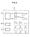
- Said manipulator 40 includes a display part disposed with manipulation buttons such as those shown in Fig. 2.
- a button 50 at "SHOWER" on the manipulator 40 is pressed first.
- a signal is output from the manipulator 40 to a manipulation signal read part 27, and said signal is input to a memory access portion 25 through a mode selective portion 27.
- Said memory access portion 25 makes access to an initialization value which has been stored in advance in a memory part 22 and sends the signal to a pump application voltage arithmetic portion 21 and a motor position arithmetic portion 24.
- the pump application voltage arithmetic portion 21 applies the output to the voltage regulator 3 and drives the pump 2 with a predetermined application voltage.
- the motor position arithmetic portion 24 applies the output to the motor driver 7 and drives the water temperature regulating motor 6 so as to set the mixing ratio of hot water to water in the mixing valve 5 at a predetermined ratio.
- a correction signal is output from the motor position arithmetic portion 24 to the motor driver 7 based on the output of a signal convertor portion 23 which has received the signal from the discharge temperature sensor 4.
- the signal which is output to the manipulation signal read portion 27 is input to the pump application voltage arithmetic portion 21 from the mode selective portion 26, and outputs a signal for altering the application voltage of the pump 2 to the voltage regulator 3.
- the pump application voltage is increased or decreased continuously or step-wise corresponding to the time of pressing the "high” button 51 or the “low” button 52 continuously.
- Alteration of the shower water temperature is made in the similar manner as above. That is, by pressing a "hot” button 53 or a “cold” button 54, a signal for driving the water temperature regulating motor 6 is output from the motor position arithmetic portion 24 to the motor driver 7. Further, it is preferable that the time of pressing the "hot” button 53 or the “cold” button 54 continuously and the driving quantity of the water temperature regulating motor 6 are made to correspond to each other.
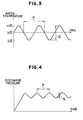
- said temperature width Q may be altered by means of a "temperature width” button 61, and said period P may be altered by means of a “period” button 62 of the manipulator 40, respectively. Furthermore, it is possible to have a newly set temperature variation pattern stored in the memory portion 22 by providing a "memory pattern" button 63.
- the discharge pressure of the shower flow vary periodically. That is, by pressing a "high-low shower" button 70 of the manipulator 40, a signal for varying the application voltage periodically is output from the pump application voltage arithmetic portion 21 to the voltage regulator 3, thereby the hot water feeding pressure of the pump 2 to the shower head 1 is varied periodically. Accordingly, the discharge pressure of the shower flow discharged from the shower head 1 is varied periodically as shown in Fig. 4, for instance.
- the pressure width S may be altered by pressing the "high-low width” button 71 and the period R may be modified by pressing the "period” button 72 of the manipulator 40, respectively, and furthermore, a discharge pressure variation pattern after modification may be stored by pressing the "memory pattern” button 73.
- control of the hot water temperature in the hot water storage tank 11 is performed as follows.
- the controller 20 is connected to the hot water temperature sensor 14 and the heater 15 installed in the hot water storage tank 11.
- a temperature regulating part 28 of the controller 20 the temperature information from a temperature setting part 29 and the temperature information from the hot water temperature sensor 14 are compared with each other.
- a heater controller 30 controls the heater 15 intermittently based on the result of comparison mentioned above, thereby to maintain the hot water temperature of the hot water storage tank 11 at the set value.
Landscapes
- Engineering & Computer Science (AREA)
- Health & Medical Sciences (AREA)
- Physics & Mathematics (AREA)
- Public Health (AREA)
- Chemical & Material Sciences (AREA)
- General Engineering & Computer Science (AREA)
- Hydrology & Water Resources (AREA)
- Automation & Control Theory (AREA)
- Water Supply & Treatment (AREA)
- Thermal Sciences (AREA)
- General Physics & Mathematics (AREA)
- Combustion & Propulsion (AREA)
- Mechanical Engineering (AREA)
- Life Sciences & Earth Sciences (AREA)
- Epidemiology (AREA)
- General Health & Medical Sciences (AREA)
- Bathtubs, Showers, And Their Attachments (AREA)
- Domestic Hot-Water Supply Systems And Details Of Heating Systems (AREA)
- Heat-Pump Type And Storage Water Heaters (AREA)
- Massaging Devices (AREA)
- Percussion Or Vibration Massage (AREA)
- Electrical Discharge Machining, Electrochemical Machining, And Combined Machining (AREA)
Claims (8)
Priority Applications (1)
| Application Number | Priority Date | Filing Date | Title |
|---|---|---|---|
| AT88306174T ATE57405T1 (de) | 1987-07-07 | 1988-07-06 | Duschanlage. |
Applications Claiming Priority (2)
| Application Number | Priority Date | Filing Date | Title |
|---|---|---|---|
| JP17008987A JPS6415017A (en) | 1987-07-07 | 1987-07-07 | Shower system |
| JP170089/87 | 1987-07-07 |
Publications (2)
| Publication Number | Publication Date |
|---|---|
| EP0300639A1 EP0300639A1 (de) | 1989-01-25 |
| EP0300639B1 true EP0300639B1 (de) | 1990-10-10 |
Family
ID=15898440
Family Applications (1)
| Application Number | Title | Priority Date | Filing Date |
|---|---|---|---|
| EP19880306174 Expired - Lifetime EP0300639B1 (de) | 1987-07-07 | 1988-07-06 | Duschanlage |
Country Status (7)
| Country | Link |
|---|---|
| US (1) | US4869427A (de) |
| EP (1) | EP0300639B1 (de) |
| JP (1) | JPS6415017A (de) |
| KR (1) | KR920009130B1 (de) |
| AT (1) | ATE57405T1 (de) |
| DE (1) | DE3860782D1 (de) |
| ES (1) | ES2018341B3 (de) |
Families Citing this family (49)
| Publication number | Priority date | Publication date | Assignee | Title |
|---|---|---|---|---|
| IT1234267B (it) * | 1989-03-06 | 1992-05-14 | Cattani Off Augusto & Co | Disconnettore di protezione per la rete idrica, in particolare per impianti medicali |
| US5331619A (en) * | 1992-02-19 | 1994-07-19 | Bradley Corporation | Programmable control system for gas and liquid dispensing devices |
| USD349151S (en) | 1993-03-05 | 1994-07-26 | Rex Fernandez | Combined shower unit and temperature control |
| GB2302166B (en) * | 1996-01-30 | 1998-05-20 | Arthur Stanley Hunnibal | Domestic water system control |
| GB2345744B (en) * | 1999-01-12 | 2002-03-20 | Peter Frederick Wailing | A water supply system |
| US6250558B1 (en) * | 1999-08-09 | 2001-06-26 | Miguel E. Dogre Cuevas | Shower temperature and pressure control system |
| DE10060307B4 (de) * | 2000-12-06 | 2006-03-16 | Ulrich, Roland | Wasserverteilsystem |
| GB2371634B (en) * | 2001-01-30 | 2005-05-25 | Aqualisa Products Ltd | Water mixing valve apparatus |
| JP3917835B2 (ja) * | 2001-09-28 | 2007-05-23 | 横河電機株式会社 | 加圧送水ポンプシステム |
| US7690395B2 (en) | 2004-01-12 | 2010-04-06 | Masco Corporation Of Indiana | Multi-mode hands free automatic faucet |
| NZ538737A (en) * | 2005-03-10 | 2008-04-30 | Hot Water Innovations Ltd | Electronic control of water storage (hot water storage) parameters and operation |
| US7458520B2 (en) | 2005-04-19 | 2008-12-02 | Masco Corporation Of Indiana | Electronic proportioning valve |
| US7475827B2 (en) | 2005-04-19 | 2009-01-13 | Masco Corporation Of Indiana | Fluid mixer |
| US7448553B2 (en) | 2005-04-19 | 2008-11-11 | Masco Corporation Of Indiana | Fluid mixer |
| US7850098B2 (en) | 2005-05-13 | 2010-12-14 | Masco Corporation Of Indiana | Power sprayer |
| US11267003B2 (en) | 2005-05-13 | 2022-03-08 | Delta Faucet Company | Power sprayer |
| US7584898B2 (en) | 2005-07-01 | 2009-09-08 | Masco Corporation Of Indiana | Manual override for electronic proportioning valve |
| US7867172B1 (en) | 2006-11-09 | 2011-01-11 | Dingane Baruti | Combination toothbrush and peak flow meter system |
| US8438672B2 (en) | 2005-11-11 | 2013-05-14 | Masco Corporation Of Indiana | Integrated electronic shower system |
| WO2007092850A2 (en) * | 2006-02-06 | 2007-08-16 | Masco Corporation Of Indiana | Power sprayer |
| US8118240B2 (en) | 2006-04-20 | 2012-02-21 | Masco Corporation Of Indiana | Pull-out wand |
| US9243756B2 (en) | 2006-04-20 | 2016-01-26 | Delta Faucet Company | Capacitive user interface for a faucet and method of forming |
| US8089473B2 (en) | 2006-04-20 | 2012-01-03 | Masco Corporation Of Indiana | Touch sensor |
| US8365767B2 (en) | 2006-04-20 | 2013-02-05 | Masco Corporation Of Indiana | User interface for a faucet |
| US8162236B2 (en) | 2006-04-20 | 2012-04-24 | Masco Corporation Of Indiana | Electronic user interface for electronic mixing of water for residential faucets |
| JP5058749B2 (ja) * | 2006-10-27 | 2012-10-24 | 株式会社川本製作所 | 給湯装置 |
| US9243392B2 (en) | 2006-12-19 | 2016-01-26 | Delta Faucet Company | Resistive coupling for an automatic faucet |
| US7806141B2 (en) | 2007-01-31 | 2010-10-05 | Masco Corporation Of Indiana | Mixing valve including a molded waterway assembly |
| US8944105B2 (en) | 2007-01-31 | 2015-02-03 | Masco Corporation Of Indiana | Capacitive sensing apparatus and method for faucets |
| US20090047185A1 (en) * | 2007-03-06 | 2009-02-19 | Fennimore Keith A | Hydrogen generation systems |
| CA2675417C (en) | 2007-03-28 | 2015-10-13 | Masco Corporation Of Indiana | Improved capacitive touch sensor |
| WO2008130349A1 (en) | 2007-04-20 | 2008-10-30 | Kohler Co. | User interface for controlling a bathroom plumbing fixture |
| US7665483B1 (en) | 2007-10-25 | 2010-02-23 | Alberto Sid | Motorized shower diverter system |
| WO2009075858A1 (en) | 2007-12-11 | 2009-06-18 | Masco Corporation Of Indiana | Capacitive coupling arrangement for a faucet |
| US7934662B1 (en) | 2008-02-15 | 2011-05-03 | Robert Jenkins | Thermostatic water mixing unit |
| CN201203205Y (zh) * | 2008-05-06 | 2009-03-04 | 厦门市易洁卫浴有限公司 | 智能供水中央处理器 |
| US8375990B2 (en) * | 2010-02-24 | 2013-02-19 | Masco Corporation Of Indiana | Mixing valve including dual flow control |
| US8776817B2 (en) | 2010-04-20 | 2014-07-15 | Masco Corporation Of Indiana | Electronic faucet with a capacitive sensing system and a method therefor |
| US8561626B2 (en) | 2010-04-20 | 2013-10-22 | Masco Corporation Of Indiana | Capacitive sensing system and method for operating a faucet |
| JP2012127543A (ja) * | 2010-12-14 | 2012-07-05 | Panasonic Corp | 給湯機 |
| BR112014013826A8 (pt) | 2011-12-06 | 2017-06-13 | Masco Corp | torneira eletrônica |
| EP2859153A4 (de) | 2012-04-20 | 2016-06-22 | Masco Corp | Wasserhahn mit einem ausziehbaren bügel mit kapazitiver detektion |
| WO2014018564A1 (en) | 2012-07-23 | 2014-01-30 | Zieger Claus Dieter | Multiple proportion delivery systems and methods |
| JP6089990B2 (ja) * | 2013-06-14 | 2017-03-08 | 三菱電機株式会社 | 貯湯式給湯機 |
| JP2015090558A (ja) * | 2013-11-05 | 2015-05-11 | パナソニックIpマネジメント株式会社 | 水温制御装置 |
| CN106020293B (zh) * | 2016-05-17 | 2018-04-03 | 江苏大学 | 一种淋浴器水温和流量的检测控制系统 |
| JP6237943B2 (ja) * | 2017-02-01 | 2017-11-29 | 三菱電機株式会社 | 貯湯式給湯機 |
| JP7106055B2 (ja) * | 2017-07-07 | 2022-07-26 | Toto株式会社 | 浴槽用吐水装置 |
| EP3477416A1 (de) * | 2017-10-27 | 2019-05-01 | Vestel Elektronik Sanayi ve Ticaret A.S. | Vorrichtung und verfahren zur abgabe einer flüssigkeit bei einer zieltemperatur |
Family Cites Families (14)
| Publication number | Priority date | Publication date | Assignee | Title |
|---|---|---|---|---|
| US1937448A (en) * | 1931-01-26 | 1933-11-28 | Trautwein Fritz | Massaging apparatus |
| US2991481A (en) * | 1958-03-17 | 1961-07-11 | Harold M Book | Fluid distribution control system |
| JPS5537527A (en) * | 1978-09-08 | 1980-03-15 | Ebara Corp | Control method for pump speed |
| GB2048466A (en) * | 1979-04-13 | 1980-12-10 | Diffracto Ltd | Optically controlled plumbing apparatus |
| DE2925234A1 (de) * | 1979-06-22 | 1981-05-27 | H.D. Eichelberg & Co Gmbh, 5860 Iserlohn | Regelung fuer sanitaere mischbatterien |
| GB2078354A (en) * | 1980-03-28 | 1982-01-06 | Floyd Gerald William | Low-voltage pump apparatus for a domestic shower |
| JPS57212388A (en) * | 1981-06-22 | 1982-12-27 | Matsushita Electric Ind Co Ltd | Apparatus for feeding water under pressure |
| US4563780A (en) * | 1983-06-29 | 1986-01-14 | Pollack Simcha Z | Automated bathroom |
| JPS60114221A (ja) * | 1983-11-24 | 1985-06-20 | 三菱電機株式会社 | 温水シヤワ−装置 |
| KR890001016B1 (ko) * | 1984-12-11 | 1989-04-18 | 마쯔시다덴기산교 가부시기가이샤 | 탕수혼합장치 |
| JPS61170422A (ja) * | 1985-01-25 | 1986-08-01 | 松下電工株式会社 | シヤワ−装置 |
| GB2172413B (en) * | 1985-03-12 | 1988-11-02 | Caradon Mira Ltd | Water supply installation for ablutionary purposes |
| US4682728A (en) * | 1985-08-27 | 1987-07-28 | Oudenhoven Martin S | Method and apparatus for controlling the temperature and flow rate of a fluid |
| US4696428A (en) * | 1986-07-10 | 1987-09-29 | Paul Shakalis | Electronic fluid temperature flow control system |
-
1987
- 1987-07-07 JP JP17008987A patent/JPS6415017A/ja active Pending
-
1988
- 1988-06-29 US US07/213,297 patent/US4869427A/en not_active Expired - Fee Related
- 1988-07-06 DE DE8888306174T patent/DE3860782D1/de not_active Expired - Lifetime
- 1988-07-06 KR KR1019880008328A patent/KR920009130B1/ko not_active Expired
- 1988-07-06 ES ES88306174T patent/ES2018341B3/es not_active Expired - Lifetime
- 1988-07-06 EP EP19880306174 patent/EP0300639B1/de not_active Expired - Lifetime
- 1988-07-06 AT AT88306174T patent/ATE57405T1/de not_active IP Right Cessation
Also Published As
| Publication number | Publication date |
|---|---|
| ES2018341B3 (es) | 1991-04-01 |
| JPS6415017A (en) | 1989-01-19 |
| EP0300639A1 (de) | 1989-01-25 |
| DE3860782D1 (de) | 1990-11-15 |
| ATE57405T1 (de) | 1990-10-15 |
| KR920009130B1 (ko) | 1992-10-13 |
| US4869427A (en) | 1989-09-26 |
| KR890001503A (ko) | 1989-03-27 |
Similar Documents
| Publication | Publication Date | Title |
|---|---|---|
| EP0300639B1 (de) | Duschanlage | |
| US4696428A (en) | Electronic fluid temperature flow control system | |
| EP0375259B1 (de) | Warmwasserversorgungssystem | |
| US6446875B1 (en) | Water temperature and pressure control system | |
| JPH0631528Y2 (ja) | 水温及び水量の調節装置 | |
| CA2601393C (en) | Electronic proportioning valve | |
| CN101685312B (zh) | 冷热水混合装置 | |
| EP0457486A2 (de) | Regelgerät für Durchfluss und Temperatur von Fluiden | |
| JP2563270B2 (ja) | 湯水混合制御装置 | |
| JP2563269B2 (ja) | 湯水混合制御装置 | |
| EP4372517B1 (de) | Binäres array zur durchflussregelung und digitales thermostatisches regelventil | |
| JPH01276317A (ja) | 温水の温度制御方法 | |
| JPS6319480A (ja) | 湯水混合制御装置 | |
| JP3103591B2 (ja) | 給湯装置 | |
| JPH04320730A (ja) | 給水給湯装置 | |
| JP3295988B2 (ja) | 湯水混合装置 | |
| JP3261776B2 (ja) | 湯水混合装置 | |
| JP2563271B2 (ja) | 湯水混合制御装置 | |
| JPH03160511A (ja) | 湯水混合制御装置 | |
| JP2751474B2 (ja) | 湯水混合制御装置 | |
| JP3692579B2 (ja) | 湯水混合装置 | |
| JPH0777337A (ja) | 給湯制御装置 | |
| JPH04183423A (ja) | シャワー装置 | |
| JPH02161507A (ja) | 湯水混合装置 | |
| JP2762529B2 (ja) | 湯水混合制御装置 |
Legal Events
| Date | Code | Title | Description |
|---|---|---|---|
| PUAI | Public reference made under article 153(3) epc to a published international application that has entered the european phase |
Free format text: ORIGINAL CODE: 0009012 |
|
| AK | Designated contracting states |
Kind code of ref document: A1 Designated state(s): AT BE CH DE ES FR GB GR IT LI LU NL SE |
|
| 17P | Request for examination filed |
Effective date: 19890316 |
|
| 17Q | First examination report despatched |
Effective date: 19890719 |
|
| ITF | It: translation for a ep patent filed | ||
| RAP1 | Party data changed (applicant data changed or rights of an application transferred) |
Owner name: CHUBU ELECTRIC POWER COMPANY, INCORPORATED Owner name: INAX CORPORATION |
|
| GRAA | (expected) grant |
Free format text: ORIGINAL CODE: 0009210 |
|
| AK | Designated contracting states |
Kind code of ref document: B1 Designated state(s): AT BE CH DE ES FR GB GR IT LI LU NL SE |
|
| PG25 | Lapsed in a contracting state [announced via postgrant information from national office to epo] |
Ref country code: SE Effective date: 19901010 Ref country code: NL Effective date: 19901010 Ref country code: LI Effective date: 19901010 Ref country code: GR Free format text: LAPSE BECAUSE OF FAILURE TO SUBMIT A TRANSLATION OF THE DESCRIPTION OR TO PAY THE FEE WITHIN THE PRESCRIBED TIME-LIMIT Effective date: 19901010 Ref country code: CH Effective date: 19901010 Ref country code: BE Effective date: 19901010 Ref country code: AT Effective date: 19901010 |
|
| REF | Corresponds to: |
Ref document number: 57405 Country of ref document: AT Date of ref document: 19901015 Kind code of ref document: T |
|
| REF | Corresponds to: |
Ref document number: 3860782 Country of ref document: DE Date of ref document: 19901115 |
|
| ET | Fr: translation filed | ||
| REG | Reference to a national code |
Ref country code: CH Ref legal event code: PL |
|
| NLV1 | Nl: lapsed or annulled due to failure to fulfill the requirements of art. 29p and 29m of the patents act | ||
| PG25 | Lapsed in a contracting state [announced via postgrant information from national office to epo] |
Ref country code: LU Free format text: LAPSE BECAUSE OF NON-PAYMENT OF DUE FEES Effective date: 19910731 |
|
| PLBE | No opposition filed within time limit |
Free format text: ORIGINAL CODE: 0009261 |
|
| STAA | Information on the status of an ep patent application or granted ep patent |
Free format text: STATUS: NO OPPOSITION FILED WITHIN TIME LIMIT |
|
| 26N | No opposition filed | ||
| ITTA | It: last paid annual fee | ||
| PGFP | Annual fee paid to national office [announced via postgrant information from national office to epo] |
Ref country code: GB Payment date: 19980626 Year of fee payment: 11 |
|
| PGFP | Annual fee paid to national office [announced via postgrant information from national office to epo] |
Ref country code: ES Payment date: 19980716 Year of fee payment: 11 |
|
| PGFP | Annual fee paid to national office [announced via postgrant information from national office to epo] |
Ref country code: FR Payment date: 19980729 Year of fee payment: 11 |
|
| PGFP | Annual fee paid to national office [announced via postgrant information from national office to epo] |
Ref country code: DE Payment date: 19980827 Year of fee payment: 11 |
|
| PG25 | Lapsed in a contracting state [announced via postgrant information from national office to epo] |
Ref country code: GB Free format text: LAPSE BECAUSE OF NON-PAYMENT OF DUE FEES Effective date: 19990706 |
|
| PG25 | Lapsed in a contracting state [announced via postgrant information from national office to epo] |
Ref country code: ES Free format text: LAPSE BECAUSE OF NON-PAYMENT OF DUE FEES Effective date: 19990707 |
|
| PG25 | Lapsed in a contracting state [announced via postgrant information from national office to epo] |
Ref country code: FR Free format text: THE PATENT HAS BEEN ANNULLED BY A DECISION OF A NATIONAL AUTHORITY Effective date: 19990731 |
|
| GBPC | Gb: european patent ceased through non-payment of renewal fee |
Effective date: 19990706 |
|
| PG25 | Lapsed in a contracting state [announced via postgrant information from national office to epo] |
Ref country code: DE Free format text: LAPSE BECAUSE OF NON-PAYMENT OF DUE FEES Effective date: 20000503 |
|
| REG | Reference to a national code |
Ref country code: FR Ref legal event code: ST |
|
| REG | Reference to a national code |
Ref country code: ES Ref legal event code: FD2A Effective date: 20000810 |
|
| PG25 | Lapsed in a contracting state [announced via postgrant information from national office to epo] |
Ref country code: IT Free format text: LAPSE BECAUSE OF NON-PAYMENT OF DUE FEES;WARNING: LAPSES OF ITALIAN PATENTS WITH EFFECTIVE DATE BEFORE 2007 MAY HAVE OCCURRED AT ANY TIME BEFORE 2007. THE CORRECT EFFECTIVE DATE MAY BE DIFFERENT FROM THE ONE RECORDED. Effective date: 20050706 |