EP0300903A1 - Fahrbare Bedienungseinheit mit symmetrisch bewegbaren Schubladen zum Lagern von Hilfswerkzeugen - Google Patents
Fahrbare Bedienungseinheit mit symmetrisch bewegbaren Schubladen zum Lagern von Hilfswerkzeugen Download PDFInfo
- Publication number
- EP0300903A1 EP0300903A1 EP88401882A EP88401882A EP0300903A1 EP 0300903 A1 EP0300903 A1 EP 0300903A1 EP 88401882 A EP88401882 A EP 88401882A EP 88401882 A EP88401882 A EP 88401882A EP 0300903 A1 EP0300903 A1 EP 0300903A1
- Authority
- EP
- European Patent Office
- Prior art keywords
- supports
- mobile
- chassis
- trolley according
- fixed
- Prior art date
- Legal status (The legal status is an assumption and is not a legal conclusion. Google has not performed a legal analysis and makes no representation as to the accuracy of the status listed.)
- Withdrawn
Links
- 238000003860 storage Methods 0.000 claims abstract description 37
- 230000005484 gravity Effects 0.000 claims description 7
- 230000002093 peripheral effect Effects 0.000 claims description 4
- 230000001681 protective effect Effects 0.000 claims description 2
- 238000005096 rolling process Methods 0.000 claims description 2
- 238000003754 machining Methods 0.000 description 2
- 235000021185 dessert Nutrition 0.000 description 1
- 235000011850 desserts Nutrition 0.000 description 1
- 238000012432 intermediate storage Methods 0.000 description 1
- 239000002184 metal Substances 0.000 description 1
- 230000000135 prohibitive effect Effects 0.000 description 1
Images
Classifications
-
- B—PERFORMING OPERATIONS; TRANSPORTING
- B25—HAND TOOLS; PORTABLE POWER-DRIVEN TOOLS; MANIPULATORS
- B25H—WORKSHOP EQUIPMENT, e.g. FOR MARKING-OUT WORK; STORAGE MEANS FOR WORKSHOPS
- B25H3/00—Storage means or arrangements for workshops facilitating access to, or handling of, work tools or instruments
- B25H3/06—Trays
Definitions
- the invention relates to a trolley for storing and classifying work accessories - in particular tools - comprising a chassis, a plurality of storage supports associated with the chassis at different heights one above the other, some of these supports. storage being associated with the chassis in a mobile manner so that it can either be retracted inside the chassis and thus limit the external bulk of the trolley, or deployed outwards in order to make the accessories accessible.
- the invention therefore aims to remedy the aforementioned drawbacks of known mobile trolleys, and relates to a trolley with movable storage supports offering a larger storage area than the trolleys of the prior art, having a smaller footprint possible when not in use or on the move, so as not to interfere with the maneuvers and movements of the people circulating around, providing immediate accessibility to the accessories it supports, and whose balance is always perfectly preserved, even during deployment and retraction maneuvers of the storage supports, and even when said accessories are heavy objects such as hand tools or for machine tools.
- Another object of the invention is to provide such a service which is more secure in use than the services of the prior art.
- Another object of the invention is to provide such a service, the cost price of which is as low as possible.
- Another object of the invention is to provide such a service for which the maneuvers for deploying and retracting the storage supports are simple, rapid, and do not require the unloading of the storage supports.
- the invention provides a service of the type mentioned above, characterized in that it comprises, for each level of mobile storage support, a plurality of such supports distributed regularly at the same height symmetrically around the service, and in that the supports of the same level are associated with the chassis so that their deployment and retraction paths are symmetrical around the service, the supports always being, even in the deployed position, symmetrically distributed around the service .
- the supports of the same level are mechanically associated with each other by association means permanently imposing a symmetrical configuration of these supports around the service, a movement of retraction or deployment given to the '' one of the mobile supports automatically generating a movement of retraction or deployment of other mobile supports of the same level in the same proportions and symmetrically by in relation to the service.
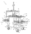
- the invention relates to a trolley 1 for storing and classifying work accessories - in particular tools -.
- the embodiment shown and described is more particularly suitable for storing, classifying and transporting tools for machining machines in a workshop and in the immediate vicinity of the workplace. It therefore allows the user to have his tools at hand at all times near the machine.
- the trolley 1 comprises a chassis 2, and a plurality of storage supports 3 associated with the chassis 2 at different heights one above the other - some 3b of these storage supports 3 being associated with the chassis 2 in a mobile manner to be able to be either retracted inside 4 of the space delimited by the chassis 2, and thus limit the external bulk of the trolley 1, or deployed outwards 5 in order to make the accessories accessible and visible.
- a service 1 comprises, in particular and preferably for each level of mobile storage supports 3b, a plurality of such supports 3b distributed regularly - notably at the same height - and symmetrically around the service 1, and the supports 3b mobile - in particular and preferably of the same level - are associated with the chassis 2 so that their deployment and retraction trajectories are symmetrical around the service 1, so that these supports 3b are always, and even in position deployed, symmetrically distributed around the service 1. The balance of the service 1 is therefore not modified during the retraction and deployment maneuvers.
- the deployment and retraction paths are preferably symmetrical around a vertical passing through the center of gravity or in the vicinity of this center of gravity of the service 1. Thus, this center of gravity is not or only slightly modified during deployment and retraction maneuvers and the balance is not changed.
- the deployment and retraction paths of the mobile storage supports 3b of a trolley according to the invention are located in a horizontal plane.
- the fixed storage supports 3a, 3b rigidly associated immobile with the frame 2 are also regularly distributed and symmetrically around the service 1, in particular symmetrically around a theoretical vertical passing through or near the lift center of the service 1 , so that the vertical of the center of gravity is confused with or close to the vertical of the center of lift.
- the movable supports 3b of the same level are mechanically associated with each other by means 6 of association - in particular comprising at least one pentograph - permanently imposing a symmetrical configuration of these supports 3b around the service 1 - notably around the theoretical vertical passing through the lift center -.
- a retraction movement in deployment given to one of the mobile supports 3b automatically generates a retraction movement or deployment of other mobile supports of the same level in the same proportions and symmetrically with respect to the service 1 - in particular relative to the vertical of the lift center.
- the center of gravity of the mobile supports 3b of the same level passes through the vertical of the lift center or in the vicinity of this vertical, and at least through the lift surface.
- Lift center the barycenter of the lift surface of the service 1.
- the supports 3 of the same level are regularly distributed around a theoretical vertical passing through the center of lift of the service, and the deployment and retraction trajectories of the mobile supports 3b are symmetrical around the theoretical vertical passing through the center of gravity of the service 1.
- each mobile support 3b consists of a horizontal plate associated with the chassis 2 by means 7 of rails, slides, rollers or the like allowing deployment to the outside 5 and a retraction to the inside 4 in horizontal translation of this plate 3b.
- the different mobile storage supports 3b of the same level all have the same shape and the same dimensions to constitute the same portion of storage support and classification of a level of the service 1 according to the invention which comprises, at a given level, either only mobile storage supports 3b retractable and capable of being deployed, or only fixed storage supports 3a or 3c.
- the chassis 2 is constituted by a horizontal fixed lower plate 3a, by two uprights 8 in the form of rectangular plates, rigidly associated with the peripheral edges 9 of the lower plate 3a to extend vertically, upwards, facing one of the other and parallel to each other, and a horizontal fixed upper plate 3c rigidly associated with the upper part of the uprights 8 so as to be less substantially opposite the lower plate 3a, the mobile storage supports 3b being associated with the uprights 8 between these two fixed plates 3a, 3c.
- the two fixed plates lower 3a and upper 3c advantageously have the same shape, in particular at least substantially rectangular.
- the rectangular uprights 8 are rigidly associated with the fixed plates 3a, 3c by their edges 10 of shorter length extending parallel and on a limited median part of the peripheral edges 9, 12 of the fixed plates 3a, 3c, the edges 11 of greater length of the uprights 8 extending vertically between the fixed plates 3a, 3c.
- the uprights 8 therefore do not cover an entire face of the service 1 and extend horizontally over only part of the storage supports 3. Thus, these supports are better accessible and visible from the outside 5.
- the weight and the cost price of the trolley 1 are all the more reduced.
- the chassis 2 does not have any other structure extending vertically than these structures 8.
- the trolley 1 as shown comprises storage supports 3 on three different levels: a lower level constituted by the lower fixed plate 3a of the chassis 2, an upper level constituted by the upper fixed plate 3c of the chassis 2, and an intermediate level consisting of two horizontal movable plates 3b of the same shape and dimensions extending in the extension of one another between the two uprights 8.
- the fixed lower 3a and upper 3c trays have the same rectangular shape and the same dimensions and the two intermediate mobile trays 3b form in the retracted state a rectangle of the same shapes and dimensions as the fixed trays 3a, 3c.
- Each mobile plate 3b corresponds to half of a fixed plate 3a, 3c, and forms half of an intermediate storage level.
- the mobile trays 3b are associated with the chassis 2 by means 7 similar to those which would be used for extension drawers.
- These association means 7 consist of rails 7 integral with the uprights and guide wheels with horizontal axes associated with the lateral edges of the plates 3b to cooperate with the rails 7.
- the two movable plates 3b are associated with the uprights 8 by the same horizontal rails 7 integral with the uprights 8 and rigidly associated with these uprights 8, each plate 3b comprising guide rollers cooperating with these rails 7.
- a rail 7 is therefore common to the two movable plates 3b.
- the service 1 in this case comprises two such rails 7, each rail 7 being associated with an upright 8 and this, so as to extend horizontally substantially halfway up the upright 8 against and parallel to its face facing inward 4.
- the two intermediate mobile plates 3b are associated with each other by association means 6 which cooperate with their internal edges facing 13.
- the two intermediate mobile plates 3b are associated with one to the other by a pentograph device 6 whose central point 14 is articulated to a cross member 15 of the chassis 2 extending horizontally perpendicular to the uprights 8 between the two horizontal rails 7 for guiding the plates 3b.
- the two free ends of the pentograph 6 are associated respectively articulated with the two internal edges 13 of the movable plates 3b.
- the pentograph 6 can be simple, and then forms two deformable parallelograms having a common vertex and the adjacent sides of the vertex in extension.
- the pentograph 6 consists of two rigid central rods hinged to one another and to the cross member 15 of the chassis in their middle 14 forming the central point of the pentograph.
- two extreme rigid rods whose length is half that of the central rods, are articulated by one of their ends respectively at the free ends of the central rods and by their other end one at the other and in the middle of the internal edge 13 of the movable plates 3b.
- the pentograph 6 may, as a variant, be multiple and form a plurality of deformable parallelograms having two by two a vertex and sides adjacent to the common vertex in extension.
- the central point 14 of association with the cross-member 15 of the chassis 2 is always a vertex common to two parallelograms, and the pentograph is symmetrical with respect to this common vertex 14.
- Each fixed or mobile tray 3 for storage advantageously consists of a metal frame 16 with which housing 17 calibrated tool holder are rigidly associated.
- the lower plate 3a which is less accessible, may not include such housings 17, but simply a horizontal plate 18 for placing loose accessories.
- the trolley 1 comprises means 19 for bearing associated with the lower plate 3a of the chassis 2 and making it possible to move the service unit 1 as a whole by making it roll.
- These rolling means advantageously consist of four associated wheels articulated at the four corners of the frame 16 of the lower plate 3a and preferably comprise integrated braking means 21.
- the upper plate 3c is provided with a guide bar 20 making it possible to roll the trolley 1.
- Each movable intermediate plate 3b is extended towards the outside 5 by a gripping and protective bar 22 extending parallel to the external edge 23 of this plate 3b and rigidly associated with this edge 23.
- the dessert 1 comprises an upper shelf 24 rigidly associated and fixed above and at a distance from the upper fixed plate 3c, this shelf 24 making it possible to temporarily deposit the accessories in use without storing them in a support.
- the upper shelf 24 can be associated with the upper tray 3c by two uprights 25 extending upwards from two corners of the upper tray 3c, and by brackets 26 associated with the uprights 25.
- Trolley 1 can be used in the following way. To move it, the movable plates 3b are retracted inwards 4 and the brakes are released 21. In this state, the outer edges of the fixed plates 3a, 3c and the space requirement of the service is minimal. The movement of the trolley 1 can be done without danger to the place of use of the tools or accessories. The braking means 21 are then blocked and the movable plates 3b deployed. In this state, the storage supports 3 are perfectly visible and accessible, and therefore also the tools or accessories. The bars 22 associated with the mobile plates are rounded and protect the user if he were to bump against the mobile plates 36 deployed. The balance of the service is perfectly preserved, even in the deployed state.
- the trolley 1 according to the invention can be the subject of numerous variants obvious to a person skilled in the art, in particular with regard to the number and the shape of the nature of the fixed or mobile supports 3.
- the mobile trays 3b can be replaced by drawers.
Landscapes
- Engineering & Computer Science (AREA)
- Mechanical Engineering (AREA)
- Warehouses Or Storage Devices (AREA)
- Handcart (AREA)
Applications Claiming Priority (2)
| Application Number | Priority Date | Filing Date | Title |
|---|---|---|---|
| FR8710219A FR2618365B1 (fr) | 1987-07-20 | 1987-07-20 | Desserte de rangement et de classement d'accessoires de travail a supports de rangement mobiles symetriquement repartis |
| FR8710219 | 1987-07-20 |
Publications (1)
| Publication Number | Publication Date |
|---|---|
| EP0300903A1 true EP0300903A1 (de) | 1989-01-25 |
Family
ID=9353315
Family Applications (1)
| Application Number | Title | Priority Date | Filing Date |
|---|---|---|---|
| EP88401882A Withdrawn EP0300903A1 (de) | 1987-07-20 | 1988-07-20 | Fahrbare Bedienungseinheit mit symmetrisch bewegbaren Schubladen zum Lagern von Hilfswerkzeugen |
Country Status (2)
| Country | Link |
|---|---|
| EP (1) | EP0300903A1 (de) |
| FR (1) | FR2618365B1 (de) |
Cited By (2)
| Publication number | Priority date | Publication date | Assignee | Title |
|---|---|---|---|---|
| EP2428327A3 (de) * | 2010-08-13 | 2015-10-07 | Hazet-Werk Hermann Zerver GmbH & Co. KG | Werkstattwagen |
| CN116140096A (zh) * | 2022-12-16 | 2023-05-23 | 江阴精力机械有限公司 | 一种升降滑撬 |
Families Citing this family (3)
| Publication number | Priority date | Publication date | Assignee | Title |
|---|---|---|---|---|
| DE29503956U1 (de) * | 1995-03-08 | 1995-08-17 | Hoffmann, Gerhard, 79541 Lörrach | Mehrzweck-Material-Transport-Wagen-Rolli |
| DE19928977A1 (de) * | 1999-06-24 | 2000-12-28 | Volkswagen Ag | Mobile Werkzeugablage und Montageplattform für eine solche Werkzeugablage |
| DE19928978B4 (de) * | 1999-06-24 | 2016-02-04 | Volkswagen Ag | Werkzeugablage |
Citations (5)
| Publication number | Priority date | Publication date | Assignee | Title |
|---|---|---|---|---|
| DE837830C (de) * | 1951-04-13 | 1952-05-02 | Richard Abr Herder Fa | Fahrbarer Werkzeugbehaelter |
| CH424677A (de) * | 1964-04-27 | 1966-11-15 | Draper & Son Limited B | Werkzeugkiste |
| GB2086851A (en) * | 1980-11-11 | 1982-05-19 | Chen Ming Tang | Portable and extensible case |
| FR2515948A1 (fr) * | 1981-11-12 | 1983-05-13 | Pasquier Roger | Magasin-presentoir pour outils |
| DE3217728A1 (de) * | 1982-05-12 | 1983-11-24 | GESA Gebr. Salmen, 5750 Menden | Fahrbarer werkzeugschrank |
-
1987
- 1987-07-20 FR FR8710219A patent/FR2618365B1/fr not_active Expired - Fee Related
-
1988
- 1988-07-20 EP EP88401882A patent/EP0300903A1/de not_active Withdrawn
Patent Citations (5)
| Publication number | Priority date | Publication date | Assignee | Title |
|---|---|---|---|---|
| DE837830C (de) * | 1951-04-13 | 1952-05-02 | Richard Abr Herder Fa | Fahrbarer Werkzeugbehaelter |
| CH424677A (de) * | 1964-04-27 | 1966-11-15 | Draper & Son Limited B | Werkzeugkiste |
| GB2086851A (en) * | 1980-11-11 | 1982-05-19 | Chen Ming Tang | Portable and extensible case |
| FR2515948A1 (fr) * | 1981-11-12 | 1983-05-13 | Pasquier Roger | Magasin-presentoir pour outils |
| DE3217728A1 (de) * | 1982-05-12 | 1983-11-24 | GESA Gebr. Salmen, 5750 Menden | Fahrbarer werkzeugschrank |
Cited By (2)
| Publication number | Priority date | Publication date | Assignee | Title |
|---|---|---|---|---|
| EP2428327A3 (de) * | 2010-08-13 | 2015-10-07 | Hazet-Werk Hermann Zerver GmbH & Co. KG | Werkstattwagen |
| CN116140096A (zh) * | 2022-12-16 | 2023-05-23 | 江阴精力机械有限公司 | 一种升降滑撬 |
Also Published As
| Publication number | Publication date |
|---|---|
| FR2618365A1 (fr) | 1989-01-27 |
| FR2618365B1 (fr) | 1991-10-11 |
Similar Documents
| Publication | Publication Date | Title |
|---|---|---|
| EP0337043B1 (de) | Einkaufswagen mit schwenkbarem Korb | |
| US6641147B2 (en) | Modified shopping cart with large item carrier | |
| US5265893A (en) | Grocery cart shelf | |
| CA2589316C (en) | Improved stackable basket | |
| US2590285A (en) | Nesting marketing carrier | |
| EP0300903A1 (de) | Fahrbare Bedienungseinheit mit symmetrisch bewegbaren Schubladen zum Lagern von Hilfswerkzeugen | |
| EP2590849B1 (de) | Einkaufswagen | |
| CA2397945A1 (fr) | Panier pour chariot de magasin en libre service | |
| FR2876641A1 (fr) | Ensemble de tablette de coffre pour vehicule automobile et vehicule correspondant. | |
| EP0349423B1 (de) | Stapelbarer Einkaufswagen mit einziehbarer Ablage unter dessen Korb | |
| FR2633589A1 (fr) | Conteneur presentoir | |
| FR2470719A1 (fr) | Chariot de transport d'ustensiles et de produits de nettoyage | |
| FR3101088A1 (fr) | Echafaudage | |
| WO1998005542A1 (fr) | Chariot multi-usages du genre diable | |
| FR2899782A1 (fr) | Dispositif de stockage a etageres, a caisson rigide inferieur et caisson deformable superieur | |
| FR2855954A1 (fr) | Etal notamment pour fruits et legumes | |
| KR200212009Y1 (ko) | 다단계 접철식 선반카트 | |
| EP1057595A1 (de) | Zusammenklappbarer Arbeitsbock | |
| FR2690319A1 (fr) | Boîte de rangement à multicompartiments emboitables. | |
| FI83497C (fi) | Rullvagn. | |
| FR3166131A1 (fr) | Chariot de transport à parois télescopiques et pliables | |
| FR2873558A1 (fr) | Meuble d'exposition modulable sous forme de gradin | |
| FR2700999A1 (fr) | Dispositif servant à déplacer les "flippers" ou table de jeux montés sur pied. | |
| FR3145887A1 (fr) | Dispositif pliant de support d’outils ou d’accessoires et son procede d’installation | |
| FR3094685A1 (fr) | Chariot pour supporter et peser un composant |
Legal Events
| Date | Code | Title | Description |
|---|---|---|---|
| PUAI | Public reference made under article 153(3) epc to a published international application that has entered the european phase |
Free format text: ORIGINAL CODE: 0009012 |
|
| AK | Designated contracting states |
Kind code of ref document: A1 Designated state(s): BE CH DE ES FR GB IT LI NL SE |
|
| 17P | Request for examination filed |
Effective date: 19890711 |
|
| 17Q | First examination report despatched |
Effective date: 19910617 |
|
| STAA | Information on the status of an ep patent application or granted ep patent |
Free format text: STATUS: THE APPLICATION IS DEEMED TO BE WITHDRAWN |
|
| 18D | Application deemed to be withdrawn |
Effective date: 19921017 |