EP0300911A1 - Dispositif de verrouillage de l'arbre de direction - Google Patents
Dispositif de verrouillage de l'arbre de direction Download PDFInfo
- Publication number
- EP0300911A1 EP0300911A1 EP19880401894 EP88401894A EP0300911A1 EP 0300911 A1 EP0300911 A1 EP 0300911A1 EP 19880401894 EP19880401894 EP 19880401894 EP 88401894 A EP88401894 A EP 88401894A EP 0300911 A1 EP0300911 A1 EP 0300911A1
- Authority
- EP
- European Patent Office
- Prior art keywords
- key cylinder
- key
- lock system
- steering lock
- pulled out
- Prior art date
- Legal status (The legal status is an assumption and is not a legal conclusion. Google has not performed a legal analysis and makes no representation as to the accuracy of the status listed.)
- Granted
Links
Images



Classifications
-
- B—PERFORMING OPERATIONS; TRANSPORTING
- B60—VEHICLES IN GENERAL
- B60R—VEHICLES, VEHICLE FITTINGS, OR VEHICLE PARTS, NOT OTHERWISE PROVIDED FOR
- B60R25/00—Fittings or systems for preventing or indicating unauthorised use or theft of vehicles
- B60R25/01—Fittings or systems for preventing or indicating unauthorised use or theft of vehicles operating on vehicle systems or fittings, e.g. on doors, seats or windscreens
- B60R25/02—Fittings or systems for preventing or indicating unauthorised use or theft of vehicles operating on vehicle systems or fittings, e.g. on doors, seats or windscreens operating on the steering mechanism
- B60R25/021—Fittings or systems for preventing or indicating unauthorised use or theft of vehicles operating on vehicle systems or fittings, e.g. on doors, seats or windscreens operating on the steering mechanism restraining movement of the steering column or steering wheel hub, e.g. restraining means controlled by ignition switch
- B60R25/02142—Fittings or systems for preventing or indicating unauthorised use or theft of vehicles operating on vehicle systems or fittings, e.g. on doors, seats or windscreens operating on the steering mechanism restraining movement of the steering column or steering wheel hub, e.g. restraining means controlled by ignition switch comprising externally controlled safety devices for preventing locking during vehicle running condition
-
- Y—GENERAL TAGGING OF NEW TECHNOLOGICAL DEVELOPMENTS; GENERAL TAGGING OF CROSS-SECTIONAL TECHNOLOGIES SPANNING OVER SEVERAL SECTIONS OF THE IPC; TECHNICAL SUBJECTS COVERED BY FORMER USPC CROSS-REFERENCE ART COLLECTIONS [XRACs] AND DIGESTS
- Y10—TECHNICAL SUBJECTS COVERED BY FORMER USPC
- Y10T—TECHNICAL SUBJECTS COVERED BY FORMER US CLASSIFICATION
- Y10T70/00—Locks
- Y10T70/50—Special application
- Y10T70/5889—For automotive vehicles
- Y10T70/5925—Transmission
- Y10T70/5934—Selective-type shift rod, fork or block
- Y10T70/5938—With switch
-
- Y—GENERAL TAGGING OF NEW TECHNOLOGICAL DEVELOPMENTS; GENERAL TAGGING OF CROSS-SECTIONAL TECHNOLOGIES SPANNING OVER SEVERAL SECTIONS OF THE IPC; TECHNICAL SUBJECTS COVERED BY FORMER USPC CROSS-REFERENCE ART COLLECTIONS [XRACs] AND DIGESTS
- Y10—TECHNICAL SUBJECTS COVERED BY FORMER USPC
- Y10T—TECHNICAL SUBJECTS COVERED BY FORMER US CLASSIFICATION
- Y10T70/00—Locks
- Y10T70/50—Special application
- Y10T70/5889—For automotive vehicles
- Y10T70/5956—Steering mechanism with switch
-
- Y—GENERAL TAGGING OF NEW TECHNOLOGICAL DEVELOPMENTS; GENERAL TAGGING OF CROSS-SECTIONAL TECHNOLOGIES SPANNING OVER SEVERAL SECTIONS OF THE IPC; TECHNICAL SUBJECTS COVERED BY FORMER USPC CROSS-REFERENCE ART COLLECTIONS [XRACs] AND DIGESTS
- Y10—TECHNICAL SUBJECTS COVERED BY FORMER USPC
- Y10T—TECHNICAL SUBJECTS COVERED BY FORMER US CLASSIFICATION
- Y10T70/00—Locks
- Y10T70/50—Special application
- Y10T70/5889—For automotive vehicles
- Y10T70/5969—Other element with switch
Definitions
- This invention relates to improvements in a steering lock system for locking a steering mechanism, and more particularly to the steering lock system which is enabled to operate only when a vehicle is in a parking condition.
- Automotive vehicles are usually equipped with a steering lock system which is operated to lock a steering shaft of a steering mechanism when an ignition key is pulled out of a key cylinder after the key cylinder is rotated from an ACC (accessory) position to a LOCK (locking) position by an ignition key, thereby preventing the vehicle from burglary.
- the key cylinder has an OFF position for switching OFF an electric system of the vehicle, positioned between the LOCK position and the ACC position.
- the ACC position is followed by an ON position for switching OFF the ignition system of an engine, a START position for operating a starter motor and the like.
- Such a steering lock system is such arranged that the ignition key is disabled from being pulled out of the key cylinder at the positions other than the LOCK position. However, if the key cylinder is carelessly rotated from the ACC position to the LOCK position, the ignition key is enabled to be pulled out of the key cylinder, which is not desirable from the viewpoint of safety.
- the key cylinder is once restrained from rotation toward the LOCK position when the key cylinder comes from the ACC position to the OFF position; and the key cylinder cannot be rotated to the LOCK position if such restraining is cancelled upon operating a cancellation button, thus attaining safety.
- Such an arrangement is disclosed, for example, in Japanese Patent Provisional Publication No. 57-164841.
- the steering lock system is comprised of a selected position sensor for detecting a selected position of a shift lever.
- the selected position sensor is adapted to produce a parking position signal when the selected position corresponds to a parking condition of the vehicle.
- An ignition key is insertable into a key cylinder which is rotatable to take a LOCK position by the ignition key. At the LOCK position, the ignition key is pulled out of the key cilinder.
- a locking mechanism is provided to lock a steering mechanism of the vehicle when the ignition key is pulled out of the key cylinder.
- a control device is provided to control operation of the ignition key relative to the key cylinder, in which the ignition key is enabled to be pulled out of the key cylinder only in response to the parking position signal from the selected position sensor, while the ignition key is disabled from being pulled out of the key cylinder upon absence of the parking position signal.
- the parking position signal is output from the selected position sensor, so that the ignition key is enabled to be pulled out of the key cylinder thereby to lock the steering mechanism. If the shift lever is out of the parking position, the ignition key cannot be pulled out of the key cylinder thereby to prevent lock of the steering mechanism.
- the steering lock system is improved in reliability and facilitated in operation as compared with conventional ones.
- a steering lock system 6 for a vehicle in accordance with the present invention.
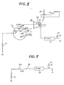
- the steering lock system is incorporated with a steering system or mechanism S of an automotive vehicle equipped with an automatic transmission 25 (See Fig. 8).
- the steering system includes a steering shaft 2 on which a steering wheel 5 is fixedly mounted.
- a column cover 4 is disposed around the steering shaft 3 and in an opening (no numeral) formed in an instrument panel 1.
- the instrument panel 1 is formed with a hole 1a for a key cylinder assembly 7.
- the steering lock system 6 includes the key cylinder assembly 7 which is connected through a cylindrical arm 7c with an installation section 7a.
- the installation section 7a is constructed of semicylindrical members which are fastened with each other and mounted on an end section of the steering column 3 so that the key cylinder assembly 7 is supported by the steering column 3.
- the key cylinder assembly 7 includes a cylindrical housing 7b disposed in the vicinity of the hole 1a and provided at its one end with a cap 8 which is fitted in the hole 1a as shown in Fig. 1 and 11.
- a key cylinder 9 having a bottom wall is disposed within the cylindrical housing 7b and rotatable around the axis thereof.
- An ignition switch 10 is fittingly secured to the other end of the cylindrical housing 7b.
- the key cylinder 9 is integrally formed at its one end with a connecting shaft 11 which extends axially to engage with the ignition switch 10 in such a manner as to rotate a movable contact 10a (Fig. 8) of the ignition switch 10.
- the key cylinder 9 has a LOCK position, an OFF position, a ACC (accessory) position for passing electric current through accessories, an ON position for switching ON an engine ignition system, and a START position for switching ON an engine starter motor.
- the key cylinder 9 is formed at its one end section outer peripheral surface with a rotor 12, a cam 13, a stopper projection 14 and another cam 15.
- the cam 13 has an inclined cam face 13a′, horizontal cam faces 13a, 13c extending in the peripheral direction of the key cylinder 9, and another inclined cam face 13c.
- the inclined cam face 13a′, 13c is inclined relative to a plane perpendicular to the axis of the key cylinder 9, while the horizontal cam face 13a, 13c is parallel with the same plane.
- the horizontal cam face 13a is contiguous with the inclined cam face 13a′.
- the horizontal cam faces 13a, 13c are contiguously connected each other through the inclined cam face 13a.
- the inclined cam face 13a faces and is spaced from the stopper projection 14.
- the horizontal cam face 13c faces and is spaced from the rotor 12.
- the outer periphery of the cam 15 is adapted to move a lock rod (not shown) forward and rearward relative to the steering shaft 2.
- This lock rod is adapted to come into engagement with a lock groove (not shown) of the steering shaft 2 to lock the steering shaft 2 when the ignition key K is pulled out of the key cylinder 9 at the LOCK position.
- the lock rod is pulled out of the lock groove of the steering shaft 2 under the action of the cam 15, thus cancelling the lock condition of the steering shaft 2.
- Such a locking mechanism for the steering shaft 2 is disclosed, for example, in Japanese Patent Provisional Publication No. 57-164840. It will be understood that the locking mechanism may be replaced with other known mechanisms.
- a key cylinder rotation control device 16 is incorporated with the cylindrical housing 7b and includes a control lever 17 which is supported by the cylindrical housing 7b in such a manner as to be movable in a direction parallel with the axis of the cylindrical housing 7b. Additionally, a solenoid 18 is provided to controllably drive the control lever 17.
- the control lever 17 is formed with two cutouts 17a, 17b for the purpose of locating the lever 17.
- the control lever 17 is formed at its one end section with an engagement projection 17c which can engage with the cam 13 and the stopper projection 14.
- the control lever 17 is formed at its intermediate section with an elongate opening 17d which extends in a direction parallel with the axis of the cylindrical housing 7b.
- the cylindrical housing 7b movably supports a ball 19 which is biased toward the control lever 17 by a spring 20 so that the ball 19 is engageable with one of the cutouts 17a, 17b.
- the cutouts 17a, 17b, the ball 19 and the spring 20 constitute a mechanism for locating the control lever 17.
- the solenoid 18 is so disposed that its axis is parallel with that of the cylindrical housing 7b.
- the solenoid 18 is fixed to a plate 18a with small screws 21.
- the plate 18a is fixed to the cylindrical housing 7b with small screws (See Figs. 2 and 3).
- An arm 23 is fixed at its one end section with an actuator rod 22 of the solenoid 18.
- a pin 24 is fixed to the other end section of the arm 23 and movably inserted in the elongate hole 17d.
- the solenoid 18 is so operated that the actuator rod 22 withdraws or moves downward in Fig. 1 when electric current is passed through the solenoid 18.
- the automatic transmission 25 is equipped with a range selecting lever 27 which is operated in relation to a shift lever or selector lever 26 for selecting vehicle operating and speed ranges.
- the automatic transmission 25 is provided with an inhibitor switch 28 which serves as a selector position sensor for sensing a selected position of the selector lever 26.
- the inhibitor switch 28 includes a switch 29 which is closed when the selector lever 26 is positioned at a Park (parking) position, as shown in Fig. 9.
- the switch 29, a timer 30, and the solenoid 18 are connected, in the mentioned order, in series with the stationary contact 10b (corresponding to the OFF position of the key cylinder 9) of the ignition switch 10.
- the timer 30 is adapted to be switched OFF upon lapse of a predetermined time (for example, several tens seconds) after electric current is initiated to be passed through the timer 30.
- the movable contact of the ignition switch 10 is connected to a battery B.
- the engagement projection 17c of the control lever 17 is positioned between the inclined cam face 13a′ of the cam 13 and the stopper projection 14 as indicated by a position "P1".
- the engagement projection 17c of the control lever 17 is relatively moved in the direction of the instrument panel 1 or upwardly in Fig. 4 along the inclined cam face 13b as indicated by a positiion "P3" and thereafter relatively moved into between the horizontal cam face 13c of the cam 13 and the rotor 12 as indicated by a position "P4" in Fig. 4.
- the ball 19 shown in Fig. 1 engages with the cutout 17b so that the engagement projection 17c of the control lever 17 is maintained between the horizontal cam face 13c of the cam 13 and the rotor 12, thereby maintaining the engagement projection 17c in the peripheral direction of the stopper projection 14.
- While restraining the ignition key from being pulled out of the key cylinder has been shown and described as being accomplished by restraining the key cylinder from rotation in the above-mentioned embodiment, it will be understood that it may be accomplished by forming a notch, a hole or the like in the ignition key and by providing a member controllably engageable with the notch, the hole or the like only when the shift lever is operated to the Park position.
Landscapes
- Engineering & Computer Science (AREA)
- Mechanical Engineering (AREA)
- Lock And Its Accessories (AREA)
Applications Claiming Priority (2)
| Application Number | Priority Date | Filing Date | Title |
|---|---|---|---|
| JP18202187A JP2685185B2 (ja) | 1987-07-21 | 1987-07-21 | ステアリングロック装置 |
| JP182021/87 | 1987-07-21 |
Publications (2)
| Publication Number | Publication Date |
|---|---|
| EP0300911A1 true EP0300911A1 (fr) | 1989-01-25 |
| EP0300911B1 EP0300911B1 (fr) | 1993-11-10 |
Family
ID=16110953
Family Applications (1)
| Application Number | Title | Priority Date | Filing Date |
|---|---|---|---|
| EP19880401894 Expired - Lifetime EP0300911B1 (fr) | 1987-07-21 | 1988-07-21 | Dispositif de verrouillage de l'arbre de direction |
Country Status (4)
| Country | Link |
|---|---|
| US (1) | US4982584A (fr) |
| EP (1) | EP0300911B1 (fr) |
| JP (1) | JP2685185B2 (fr) |
| DE (1) | DE3885526T2 (fr) |
Cited By (2)
| Publication number | Priority date | Publication date | Assignee | Title |
|---|---|---|---|---|
| US5014038A (en) * | 1987-09-14 | 1991-05-07 | Automotive Products (Usa) Inc. | Motor vehicle control system |
| EP2213532A3 (fr) * | 2009-02-03 | 2011-03-30 | Kabushiki Kaisha Tokai Rika Denki Seisakusho | Dispositif de régulation de clé |
Families Citing this family (17)
| Publication number | Priority date | Publication date | Assignee | Title |
|---|---|---|---|---|
| JP2512154Y2 (ja) * | 1989-11-30 | 1996-09-25 | 株式会社アルファ | ステアリングロック装置 |
| US5065604A (en) * | 1990-06-11 | 1991-11-19 | Sparton Corporation | Ignition interlock system |
| JP2562690Y2 (ja) * | 1991-02-28 | 1998-02-16 | 株式会社アルファ | ステアリングロック装置のケ−ブル接続構造 |
| JPH0532180U (ja) * | 1991-10-11 | 1993-04-27 | 株式会社本田ロツク | 車両用ステアリングロツク装置 |
| JP2533684Y2 (ja) * | 1991-11-29 | 1997-04-23 | 株式会社ホンダロック | 車両用ステアリングロック装置 |
| US6501370B1 (en) | 1996-09-16 | 2002-12-31 | Frank G. Rick | Vehicle anti-theft lock apparatus and method |
| US6000489A (en) * | 1996-09-16 | 1999-12-14 | Rick; Frank G. | Anti-theft steering lock |
| JPH10119722A (ja) * | 1996-10-24 | 1998-05-12 | Yazaki Corp | ステアリングロック装置 |
| JP2001063395A (ja) * | 1999-08-31 | 2001-03-13 | Tokai Rika Co Ltd | 不正使用防止用シフトレバーロック装置 |
| US6571587B2 (en) * | 2001-01-09 | 2003-06-03 | Strattec Security Corporation | Steering column lock apparatus and method |
| JP2002308049A (ja) * | 2001-04-11 | 2002-10-23 | Tokai Rika Co Ltd | 車両用エンジン始動装置 |
| EP1378406B1 (fr) * | 2002-05-29 | 2006-09-06 | Kabushiki Kaisha Tokai Rika Denki Seisakusho | Dispositif permettant de limiter l'activation du système de démarrage d'un moteur |
| FR2848168B1 (fr) * | 2002-12-06 | 2005-10-21 | Valeo Securite Habitacle | Antivol pour vehicule automobile notamment de type electronique |
| US7140213B2 (en) * | 2004-02-21 | 2006-11-28 | Strattec Security Corporation | Steering column lock apparatus and method |
| KR100986462B1 (ko) * | 2008-11-28 | 2010-10-08 | 기아자동차주식회사 | 자동차의 키 인터록 |
| KR101094910B1 (ko) * | 2009-10-30 | 2011-12-16 | 기아자동차주식회사 | 차량의 키 인터록 장치 |
| JP5787065B2 (ja) * | 2011-04-26 | 2015-09-30 | 株式会社ユーシン | 車両用ロック装置 |
Citations (5)
| Publication number | Priority date | Publication date | Assignee | Title |
|---|---|---|---|---|
| US3401544A (en) * | 1967-01-30 | 1968-09-17 | Cyril C. Fraser | Theft protection for vehicles in parking lots |
| US3566632A (en) * | 1968-05-17 | 1971-03-02 | Chrysler Corp | Steering column and transmission control lock |
| FR2176373A5 (fr) * | 1972-03-11 | 1973-10-26 | Tokai Rika Co Ltd | |
| FR2499005A1 (fr) * | 1981-01-30 | 1982-08-06 | Neiman Sa | Antivol pour vehicule automobile |
| DE3616122A1 (de) * | 1986-05-13 | 1987-11-19 | Ymos Ag Ind Produkte | Lenk- und zuendschloss |
Family Cites Families (14)
| Publication number | Priority date | Publication date | Assignee | Title |
|---|---|---|---|---|
| US3490255A (en) * | 1967-12-19 | 1970-01-20 | Gen Motors Corp | Vehicle control locking system |
| US3590612A (en) * | 1969-11-25 | 1971-07-06 | Gen Motors Corp | Vehicle controls and coincidental lock therefor |
| US3917021A (en) * | 1973-01-23 | 1975-11-04 | Richard D Williams | Control mechanism |
| US3827526A (en) * | 1973-02-05 | 1974-08-06 | Wagner Electric Corp | Automotive security system and solenoid lock for same |
| US3940958A (en) * | 1973-12-22 | 1976-03-02 | Kabushiki Kaisha Honda Lock | Steering lock for vehicles |
| US4218717A (en) * | 1978-08-21 | 1980-08-19 | Harry Shuster | Electric control system for motor vehicle |
| US4232571A (en) * | 1979-02-12 | 1980-11-11 | General Motors Corporation | Floor mounted shift control mechanism with drive transmitting cables |
| US4258560A (en) * | 1979-06-18 | 1981-03-31 | General Motors Corporation | Shaft lock assembly for vehicle steering column |
| US4270624A (en) * | 1979-07-11 | 1981-06-02 | General Motors Corporation | Steering column lock inhibitor for a floor mounted transmission control |
| FR2499006A1 (fr) * | 1981-02-04 | 1982-08-06 | Neiman Sa | Antivol pour vehicule automobile |
| JPS57164840A (en) * | 1981-04-04 | 1982-10-09 | Nissan Motor Co Ltd | Steering lock |
| JPS57164841A (en) * | 1981-04-04 | 1982-10-09 | Nissan Motor Co Ltd | Steering lock |
| JPS60135352A (ja) * | 1984-03-27 | 1985-07-18 | Isuzu Motors Ltd | 変速レバーとハンドルのロック装置 |
| AU572514B2 (en) * | 1984-06-18 | 1988-05-12 | Isuzu Motors Ltd. | Ignition and shift lever lock |
-
1987
- 1987-07-21 JP JP18202187A patent/JP2685185B2/ja not_active Expired - Fee Related
-
1988
- 1988-07-21 DE DE88401894T patent/DE3885526T2/de not_active Expired - Fee Related
- 1988-07-21 EP EP19880401894 patent/EP0300911B1/fr not_active Expired - Lifetime
-
1989
- 1989-12-28 US US07/456,089 patent/US4982584A/en not_active Expired - Lifetime
Patent Citations (5)
| Publication number | Priority date | Publication date | Assignee | Title |
|---|---|---|---|---|
| US3401544A (en) * | 1967-01-30 | 1968-09-17 | Cyril C. Fraser | Theft protection for vehicles in parking lots |
| US3566632A (en) * | 1968-05-17 | 1971-03-02 | Chrysler Corp | Steering column and transmission control lock |
| FR2176373A5 (fr) * | 1972-03-11 | 1973-10-26 | Tokai Rika Co Ltd | |
| FR2499005A1 (fr) * | 1981-01-30 | 1982-08-06 | Neiman Sa | Antivol pour vehicule automobile |
| DE3616122A1 (de) * | 1986-05-13 | 1987-11-19 | Ymos Ag Ind Produkte | Lenk- und zuendschloss |
Cited By (4)
| Publication number | Priority date | Publication date | Assignee | Title |
|---|---|---|---|---|
| US5014038A (en) * | 1987-09-14 | 1991-05-07 | Automotive Products (Usa) Inc. | Motor vehicle control system |
| EP2213532A3 (fr) * | 2009-02-03 | 2011-03-30 | Kabushiki Kaisha Tokai Rika Denki Seisakusho | Dispositif de régulation de clé |
| US8141397B2 (en) | 2009-02-03 | 2012-03-27 | Kabushiki Kaisha Tokai-Rika-Denki-Seisakusho | Key regulating device |
| CN101793110B (zh) * | 2009-02-03 | 2014-03-19 | 株式会社东海理化电机制作所 | 钥匙限制装置 |
Also Published As
| Publication number | Publication date |
|---|---|
| JP2685185B2 (ja) | 1997-12-03 |
| US4982584A (en) | 1991-01-08 |
| DE3885526D1 (de) | 1993-12-16 |
| JPS6428054A (en) | 1989-01-30 |
| EP0300911B1 (fr) | 1993-11-10 |
| DE3885526T2 (de) | 1994-05-11 |
Similar Documents
| Publication | Publication Date | Title |
|---|---|---|
| US4982584A (en) | Steering lock system | |
| US4932493A (en) | Ignition switch, brake and gearshift interlocks for a vehicle automatic transmission | |
| US4513276A (en) | Safety system of automotive automatic transmission operating device | |
| US4843901A (en) | Electric shift apparatus with manual override | |
| US5003799A (en) | Device for locking shift lever of automatic transmission | |
| US4473141A (en) | Shift lever and parking brake control | |
| US2324819A (en) | Circuit controller | |
| US3708032A (en) | Accidental lock preventing device | |
| US4854193A (en) | Key interlock system for automatic floor mounted transmission shifter | |
| EP0449615B1 (fr) | Système d'alarme pour transmissions automatiques de véhicules | |
| GB2361104A (en) | Vehicle ignition switch | |
| US3590613A (en) | Coincidental vehicle steering column and floor shift lock | |
| US6439014B1 (en) | Shift lever device | |
| EP0548945B1 (fr) | Dispositif de commande de papillon d'admission | |
| US5255570A (en) | Safety shift-lock device for selector of automatic power transmission | |
| US3590612A (en) | Vehicle controls and coincidental lock therefor | |
| US5065135A (en) | Transmission logic controlling starter motor and backup light | |
| JP2886239B2 (ja) | 自動変速操作装置 | |
| US3419115A (en) | Starter safety switch on clutch pedal | |
| EP1076193A1 (fr) | Dispositif d'actionnement avec bouton tournant pour une transmission automatique | |
| US4934209A (en) | Steering column mounted transmission gear shift mechanism having ignition key interlock | |
| JPS6150812B2 (fr) | ||
| US6082217A (en) | Brake transmission shift interlock assembly | |
| US5861800A (en) | Ignition interlock and PRNDL indicator powering switch | |
| US3732710A (en) | Lockable steering column assembly |
Legal Events
| Date | Code | Title | Description |
|---|---|---|---|
| PUAI | Public reference made under article 153(3) epc to a published international application that has entered the european phase |
Free format text: ORIGINAL CODE: 0009012 |
|
| 17P | Request for examination filed |
Effective date: 19880801 |
|
| AK | Designated contracting states |
Kind code of ref document: A1 Designated state(s): DE GB |
|
| 17Q | First examination report despatched |
Effective date: 19900810 |
|
| RAP1 | Party data changed (applicant data changed or rights of an application transferred) |
Owner name: ALPHA CORPORATION Owner name: NISSAN MOTOR CO., LTD. |
|
| GRAA | (expected) grant |
Free format text: ORIGINAL CODE: 0009210 |
|
| AK | Designated contracting states |
Kind code of ref document: B1 Designated state(s): DE GB |
|
| REF | Corresponds to: |
Ref document number: 3885526 Country of ref document: DE Date of ref document: 19931216 |
|
| PLBE | No opposition filed within time limit |
Free format text: ORIGINAL CODE: 0009261 |
|
| STAA | Information on the status of an ep patent application or granted ep patent |
Free format text: STATUS: NO OPPOSITION FILED WITHIN TIME LIMIT |
|
| 26N | No opposition filed | ||
| REG | Reference to a national code |
Ref country code: GB Ref legal event code: IF02 |
|
| REG | Reference to a national code |
Ref country code: GB Ref legal event code: 732E |
|
| PGFP | Annual fee paid to national office [announced via postgrant information from national office to epo] |
Ref country code: GB Payment date: 20040721 Year of fee payment: 17 |
|
| PGFP | Annual fee paid to national office [announced via postgrant information from national office to epo] |
Ref country code: DE Payment date: 20040729 Year of fee payment: 17 |
|
| PG25 | Lapsed in a contracting state [announced via postgrant information from national office to epo] |
Ref country code: GB Free format text: LAPSE BECAUSE OF NON-PAYMENT OF DUE FEES Effective date: 20050721 |
|
| PG25 | Lapsed in a contracting state [announced via postgrant information from national office to epo] |
Ref country code: DE Free format text: LAPSE BECAUSE OF NON-PAYMENT OF DUE FEES Effective date: 20060201 |
|
| GBPC | Gb: european patent ceased through non-payment of renewal fee |
Effective date: 20050721 |