EP1378406B1 - Dispositif permettant de limiter l'activation du système de démarrage d'un moteur - Google Patents
Dispositif permettant de limiter l'activation du système de démarrage d'un moteur Download PDFInfo
- Publication number
- EP1378406B1 EP1378406B1 EP20030445064 EP03445064A EP1378406B1 EP 1378406 B1 EP1378406 B1 EP 1378406B1 EP 20030445064 EP20030445064 EP 20030445064 EP 03445064 A EP03445064 A EP 03445064A EP 1378406 B1 EP1378406 B1 EP 1378406B1
- Authority
- EP
- European Patent Office
- Prior art keywords
- actuator
- vehicle
- operating means
- control means
- lock position
- Prior art date
- Legal status (The legal status is an assumption and is not a legal conclusion. Google has not performed a legal analysis and makes no representation as to the accuracy of the status listed.)
- Expired - Lifetime
Links
- 230000004913 activation Effects 0.000 title claims description 29
- 230000003213 activating effect Effects 0.000 claims description 6
- 230000005540 biological transmission Effects 0.000 claims description 6
- 238000012795 verification Methods 0.000 claims description 6
- 230000000415 inactivating effect Effects 0.000 claims 1
- 239000007858 starting material Substances 0.000 description 57
- 230000007246 mechanism Effects 0.000 description 6
- 238000010586 diagram Methods 0.000 description 5
- 230000004044 response Effects 0.000 description 4
- 238000004519 manufacturing process Methods 0.000 description 3
- 230000007423 decrease Effects 0.000 description 2
- 238000001514 detection method Methods 0.000 description 2
- 238000003780 insertion Methods 0.000 description 2
- 230000037431 insertion Effects 0.000 description 2
- 230000002779 inactivation Effects 0.000 description 1
- 239000002184 metal Substances 0.000 description 1
- 230000000717 retained effect Effects 0.000 description 1
Images



Classifications
-
- F—MECHANICAL ENGINEERING; LIGHTING; HEATING; WEAPONS; BLASTING
- F02—COMBUSTION ENGINES; HOT-GAS OR COMBUSTION-PRODUCT ENGINE PLANTS
- F02N—STARTING OF COMBUSTION ENGINES; STARTING AIDS FOR SUCH ENGINES, NOT OTHERWISE PROVIDED FOR
- F02N11/00—Starting of engines by means of electric motors
- F02N11/10—Safety devices
-
- B—PERFORMING OPERATIONS; TRANSPORTING
- B60—VEHICLES IN GENERAL
- B60R—VEHICLES, VEHICLE FITTINGS, OR VEHICLE PARTS, NOT OTHERWISE PROVIDED FOR
- B60R25/00—Fittings or systems for preventing or indicating unauthorised use or theft of vehicles
- B60R25/20—Means to switch the anti-theft system on or off
- B60R25/2063—Ignition switch geometry
-
- B—PERFORMING OPERATIONS; TRANSPORTING
- B60—VEHICLES IN GENERAL
- B60R—VEHICLES, VEHICLE FITTINGS, OR VEHICLE PARTS, NOT OTHERWISE PROVIDED FOR
- B60R25/00—Fittings or systems for preventing or indicating unauthorised use or theft of vehicles
- B60R25/01—Fittings or systems for preventing or indicating unauthorised use or theft of vehicles operating on vehicle systems or fittings, e.g. on doors, seats or windscreens
- B60R25/04—Fittings or systems for preventing or indicating unauthorised use or theft of vehicles operating on vehicle systems or fittings, e.g. on doors, seats or windscreens operating on the propulsion system, e.g. engine or drive motor
-
- Y—GENERAL TAGGING OF NEW TECHNOLOGICAL DEVELOPMENTS; GENERAL TAGGING OF CROSS-SECTIONAL TECHNOLOGIES SPANNING OVER SEVERAL SECTIONS OF THE IPC; TECHNICAL SUBJECTS COVERED BY FORMER USPC CROSS-REFERENCE ART COLLECTIONS [XRACs] AND DIGESTS
- Y10—TECHNICAL SUBJECTS COVERED BY FORMER USPC
- Y10S—TECHNICAL SUBJECTS COVERED BY FORMER USPC CROSS-REFERENCE ART COLLECTIONS [XRACs] AND DIGESTS
- Y10S70/00—Locks
- Y10S70/30—Switch lock
-
- Y—GENERAL TAGGING OF NEW TECHNOLOGICAL DEVELOPMENTS; GENERAL TAGGING OF CROSS-SECTIONAL TECHNOLOGIES SPANNING OVER SEVERAL SECTIONS OF THE IPC; TECHNICAL SUBJECTS COVERED BY FORMER USPC CROSS-REFERENCE ART COLLECTIONS [XRACs] AND DIGESTS
- Y10—TECHNICAL SUBJECTS COVERED BY FORMER USPC
- Y10T—TECHNICAL SUBJECTS COVERED BY FORMER US CLASSIFICATION
- Y10T70/00—Locks
- Y10T70/50—Special application
- Y10T70/5611—For control and machine elements
- Y10T70/5646—Rotary shaft
- Y10T70/565—Locked stationary
- Y10T70/5655—Housing-carried lock
- Y10T70/5664—Latching bolt
-
- Y—GENERAL TAGGING OF NEW TECHNOLOGICAL DEVELOPMENTS; GENERAL TAGGING OF CROSS-SECTIONAL TECHNOLOGIES SPANNING OVER SEVERAL SECTIONS OF THE IPC; TECHNICAL SUBJECTS COVERED BY FORMER USPC CROSS-REFERENCE ART COLLECTIONS [XRACs] AND DIGESTS
- Y10—TECHNICAL SUBJECTS COVERED BY FORMER USPC
- Y10T—TECHNICAL SUBJECTS COVERED BY FORMER US CLASSIFICATION
- Y10T70/00—Locks
- Y10T70/50—Special application
- Y10T70/5889—For automotive vehicles
-
- Y—GENERAL TAGGING OF NEW TECHNOLOGICAL DEVELOPMENTS; GENERAL TAGGING OF CROSS-SECTIONAL TECHNOLOGIES SPANNING OVER SEVERAL SECTIONS OF THE IPC; TECHNICAL SUBJECTS COVERED BY FORMER USPC CROSS-REFERENCE ART COLLECTIONS [XRACs] AND DIGESTS
- Y10—TECHNICAL SUBJECTS COVERED BY FORMER USPC
- Y10T—TECHNICAL SUBJECTS COVERED BY FORMER US CLASSIFICATION
- Y10T70/00—Locks
- Y10T70/50—Special application
- Y10T70/5889—For automotive vehicles
- Y10T70/5925—Transmission
- Y10T70/5934—Selective-type shift rod, fork or block
-
- Y—GENERAL TAGGING OF NEW TECHNOLOGICAL DEVELOPMENTS; GENERAL TAGGING OF CROSS-SECTIONAL TECHNOLOGIES SPANNING OVER SEVERAL SECTIONS OF THE IPC; TECHNICAL SUBJECTS COVERED BY FORMER USPC CROSS-REFERENCE ART COLLECTIONS [XRACs] AND DIGESTS
- Y10—TECHNICAL SUBJECTS COVERED BY FORMER USPC
- Y10T—TECHNICAL SUBJECTS COVERED BY FORMER US CLASSIFICATION
- Y10T70/00—Locks
- Y10T70/50—Special application
- Y10T70/5889—For automotive vehicles
- Y10T70/5956—Steering mechanism with switch
Definitions
- interlocking mechanisms are included in automobiles for safety reasons.
- an interlocking mechanism restricts the activation of a steering lock apparatus by preventing a key inserted into a key cylinder from being removed.
- An electric interlocking mechanism includes a key interlocking solenoid to permit or prohibit the insertion of the key.
- DE 198 21 899 A1 relates to a rotatable ignition switch according to the preamble of claim 1 having a shaft capable of receiving an electronic key.
- the shaft comprises a switching disk having magnets interacting with fixed hall sensors for determining the amount of rotation.
- an elongated cover for entirely covering the engine starting system may be used in both automobiles equipped with the smart ignition apparatus and automobiles that are not equipped with the smart ignition apparatus.
- the knob locking solenoid becomes necessary in addition to the key interlocking solenoid.
- space for the knob locking solenoid is required in addition to the space for the key interlocking solenoid. This enlarges the entire engine starting system.
- the elongated cover that covers the engine starting system cannot be used when two solenoids are used. As a result, two types of elongated covers are necessary, and the manufacturing cost of the engine starting system cannot be reduced.
- the control means enables the engine to be started by disengaging the actuator from the first stopper when the operating means is in the LOCK position and the first ID code sent from the portable device matches a predetermined second ID code of the control means.
- the control means enables the operating means to be moved to the LOCK position by disengaging the actuator from the second stopper when the operating means is in a position other than the LOCK position and the vehicle is not moving.
- an apparatus for restricting activation of a starting system of an engine of a vehicle and for use with a portable device operable for sending a first ID code includes an operating means for manually starting and stopping the engine and having a plurality of operation positions including a LOCK position in which the operating means is locked.
- the operating means includes a first projection, which prohibits movement of the operating means from the LOCK position to a position other than the LOCK position, and a second projection, which prohibits movement of the operating means to the LOCK position from a position other than the LOCK position.
- An actuator engages the first and second stoppers.
- An intervening member is arranged between the actuator and the second projection to engage the second projection in cooperation with the actuator.
- An actuator control means is connected to the actuator to control the actuator.
- An ID code verification means is connected to the actuator control means to determine whether the first ID code when sent from the portable device matches a second ID code.
- a shift lock control means is connected to the actuator for enabling the operating means to be moved to the LOCK position by disengaging the intervening member from the second projection when the operating means is in a position other than the LOCK position and the vehicle is not moving.
- the actuator control means enables the engine to be started by disengaging the actuator from the first projection when the operating means is in the LOCK position and the first ID code matches the second ID code.
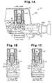
- Figs. 1A to 1C are schematic cross-sectional diagrams showing an activation restricting apparatus 100 of an engine starting system 11 according to a first embodiment of the present invention.
- the engine starting system 11 has a metal cylinder 13.
- An immobilizer amplifier 17 is connected to a lower surface of the cylinder 13.
- the cylinder 13 includes a bore 14 and an accommodating portion 16, which is connected with the bore 14.
- a camshaft 21 is retained in the bore 14.
- a starter knob 22 is connected to one end of the camshaft 21.
- the starter knob 22 is turned between an ACC position and a LOCK position.
- the starter knob 22 includes a tab 22a.
- the tab 22a is used to turn the starter knob 22. This rotates the camshaft 21 and starts or stops the engine.
- the camshaft 21 and the starter knob 22 function as an operating means.
- the camshaft 21 includes a cam 31.
- a first projection 32a which serves as a first stopper
- a second projection 32b which serves as a second stopper, extend from the surface of the cam 31.
- the first projection 32a restricts the movement of the starter knob 22 to the ACC position.
- the second projection 32b restricts the movement of the starter knob 22 to the LOCK position.
- a solenoid 41 which serves as an actuator, is attached to the cylinder 13.
- the solenoid 41 includes a plunger 42.
- a stopper pin 43 is connected to the plunger 42 by a damper 42a.
- the stopper pin 43 extends vertically in the accommodating portion 16, as viewed in Figs 1A to 1C. Further, the stopper pin 43 is movable in the vertical direction.
- the stopper pin 43 When the solenoid 41 is de-excited (inactivated) as shown in the state of Figs. 1A and 1B, the stopper pin 43 is projected to engage the first projection 32a. When the solenoid 41 is excited (activated) as shown in the state of Fig. 1C, the stopper pin 43 is retracted and disengaged from the first projection 32a. The stopper pin 43 engages the first projection 32a, for example, when the camshaft 21 is arranged at the LOCK position as shown in the state of Fig. 1B.
- a locking lever (second stopper) 44 which serves as an intervening member, is connected to the cylinder 13.
- the locking lever 44 is pivoted about a pivot pin 44a.
- the locking lever 44 has a first end (left end as viewed in Fig. 2) and a second end (right end as viewed in Fig. 2).
- the damper 42a pushes the locking lever 44 toward the first projection 32a. This moves the second end of the locking lever 44 away from the second projection 32b.
- An engaging spring 47 constantly urges the second end of the locking lever 44 toward the second projection 32b.
- a force is applied to the first end of the locking lever 44 in a direction in which the first end disengages the first projection 32a.
- the cylinder 13 has a switch 45, which serves as switching means.
- the switch 45 goes ON and OFF when the starter knob 22 is turned between the LOCK position and the ACC position. Accordingly, the switch 45 activates and inactivates the solenoid 41.
- a block 46 (cooperative member) contacts or moves away from a contact 45a of the switch 45 to activate or inactivate the solenoid 41.
- the switch 45 goes OFF and the solenoid 41 is inactivated.
- the solenoid 41 is activated.
- a spring urges the block 46 toward the contact 45a of the switch 45.
- a cam follower 46a projects from the block 46 to engage a cam surface 31a of the cam 31. The portion of the cam surface 31a that contacts the cam follower 46a moves in the axial direction of the starter knob 22 in accordance with the turning of the starter knob 22. In other words, the block 46 moves axially in accordance with the turning of the starter knob 22.
- the engine starting system 11 includes a portable device 51, a communication controller 61, the solenoid 41, a solenoid electronic control unit (ECU) 71, a switch 45, and a shift lock controller 81.
- the portable device 51 includes a receiving circuit 52, a microcomputer 53, a transmitting circuit 54, and a transponder controller 55.
- the receiving circuit 52 receives a request signal from the communication controller 61 and provides the request signal to the microcomputer 53.
- the microcomputer 53 When receiving the request signal, the microcomputer 53 generates an ID code signal.
- the ID code signal includes a predetermined ID code and serves as a transmission signal.
- the transmitting circuit 54 uses the ID code signal to modulate a wave having a predetermined frequency and transmits the modulated wave to an external device.
- the receiving circuit 52 and the transmitting circuit 54 are respectively connected to antennas 52a and 54a.
- the transponder controller 55 When the transponder controller 55 receives sufficient energy through electromagnetic waves, the transponder controller 55 generates a transponder signal, which includes a predetermined transponder ID code. More specifically, the transponder controller 55 automatically generates a transponder signal having a predetermined frequency when receiving a transponder drive wave from the communication controller. Then, the transponder controller 55 transmits the transponder signal to the communication controller 61.
- the communication controller 61 which is installed in the vehicle, includes a transmitting circuit 62, a first receiving circuit 63, a second receiving circuit 64, a switching circuit 65, and a smart ECU 66.
- the smart ECU 66 serves as a control means and an ID code verification means.
- the smart ECU 66 is connected to the first receiving circuit 63, the transmitting circuit 62, and the second receiving circuit 64.
- the first receiving circuit 63 is connected to an antenna.
- the transmitting circuit 62 and the second receiving circuit 64 are connected to the switching circuit 65.
- the switching circuit 65 selectively connects the immobilizer amplifier 17 and the antenna 17a to the transmitting circuit 62 and the second receiving circuit 64.
- the immobilizer amplifier 17 amplifies the transponder signal received by the antenna 17a and provides the amplified transponder signal to the second receiving circuit 64.
- the transmitting circuit 62 is connected to an antenna 62a, which is installed in the passenger compartment.
- the transmitting circuit 62 sends a request signal to the passenger compartment through the antenna 62a.
- the transmitting circuit 62 converts the transponder signal provided from the smart ECU 66 to a wave having a predetermined frequency and generates a transponder drive wave.
- the transponder drive wave is output through the antenna 17a.
- the second receiving circuit 64 receives a transponder signal from the portable device 51 through the antenna 17a. Then, the second receiving circuit 64 de-modulates the transponder signal to a pulse signal and generates a second receiving signal. The second receiving signal is provided to the smart ECU 66.
- the solenoid ECU 71 which serves as a control means and an actuator drive control means, is connected to the smart ECU 66.
- the solenoid ECU 71 is connected to the solenoid 41 to control the activation of the solenoid 41.
- the solenoid ECU 71, the solenoid 41, and the switch 45 are accommodated in a lock body 12, which serves as a cover.
- the portion closed by the lock body 12 serves as a hard protect area 82 in which the solenoid ECU 71, the solenoid 41, and the switch 45 are protected from external impacts.
- the shift lock controller 81 which serves as a control means, is connected to the solenoid 41 via the switch 45 and a power line 76.
- the shift lock controller 81 detects whether the shift lever is in the parking position and whether a shift button of the shift lever is not being pressed. From the detections, the shift lock controller 81 determines whether the vehicle is not moving and inactivates the solenoid 41 even if the switch 45 is ON. As shown in Fig. 4, the solenoid 41 is supplied with power from a battery via the smart ECU 66 or the shift lock controller 81.
- the solenoid ECU 71 includes a central processing unit (CPU) 72.
- the CPU 72 is connected to the base terminal of the transistor 74 via a resistor R1.
- the collector terminal of the transistor 74 is connected to the base terminal of a transistor 74a.
- the transistors 74 and 74a amplify the power supplied to the solenoid 41 by the smart ECU 66.
- a power line 75 and a signal line 73 connect the CPU 72 and the smart ECU 66 to each other. Power is supplied to the CPU 72 through the power line 75.
- the signal line 73 us used for serial communication to send information from the smart ECU 66 to the CPU 72 on whether encoded ID codes are matched.
- the smart ECU 66 which includes a CPU, a ROM, and a RAM (none of which are shown), intermittently generates a request signal.
- the smart ECU 66 has a predetermined ID code and compares its ID code with an ID code included in the first receiving signal or the second receiving signal when receiving the first or second receiving signal. When the ID codes match, the smart ECU 66 generates an activation signal and provides the activation signal to the CPU 72. Then, the CPU 72 provides the transistor 74 with the activation signal to activate the solenoid 41.
- the plunger 42 moves and disengages the stopper pin 43 from the first projection 32a to enable the turning of the starter knob.
- the starter knob 22 is turned to move the starter knob 22 from the LOCK position to the ACC position.
- the smart ECU 66 and the solenoid ECU are inactivated.
- the turning of the starter knob 22 moves the block 46 away from the contact 45a and turns ON the switch 45, as shown in the state of Fig. 6. Since the shift lever is arranged at the parking position, the solenoid 41 returns to the inactivated state, and the stopper pin 43 projects into the bore 14.
- the starter knob 22 is pushed in the axial direction, for example, when a driver does not immediately start the engine after getting into the vehicle to again request ID code verification and to enable the turning of the starter knob 22. Since the rotation of the camshaft 21 from the ACC position to the START position is enabled as shown in the state of Fig. 8, the engine may be started by activating a starting relay (not shown) to drive a starting motor (not shown). Accordingly, the engine starting system 11 functions as a smart ignition apparatus.
- the engine starting system activation restricting apparatus 100 of the first embodiment has the advantages described below.
- Fig. 11 is a cross-sectional view of an engine starting system activation restricting apparatus 200 according to a second embodiment of the present invention.
- Fig. 12 is a schematic cross-sectional view taken along line 12-12. Parts differing from the first embodiment will now be described. Identical parts will not be described.
- an engine starting system 11A includes a cylinder 13, which has an attaching portion 15 and an accommodating portion 16.
- the accommodating portion 16 is connected to a bore 14 through a plunger insertion hole 16a.
- a stopper pin 43 extends vertically through the accommodating portion 16.
- a spring 144 urges the stopper pin 43 upward, as viewed in Fig. 12.
- the first and second recesses 132a and 132b are arranged in the surface of the cam 31A.
- the dimension of the second recess 132b in the circumferential direction of the cam 31A is greater than that of the first recess 132a.
- the first recess 132a corresponds to the LOCK position of a starter knob 22.
- the second recess 132b corresponds to positions of the starter knob 22 other than the LOCK position (i.e., ACC position, ON position, and START position).
- the stopper pin 43 is engaged with and disengaged from the first recess 132a or the second recess 132b by the solenoid 41. More specifically, when the solenoid 41 is inactivated, the stopper pin 43 is held in a state engaged with the first recess 132a or the second recess 132b. When the solenoid 41 is activated, the stopper pin 43 is disengaged from the first recess 132a or the second recess 132b. When a camshaft 21 is located at a position corresponding to the LOCK position, the stopper pin 43 engages the first recess 132a. As shown in the state of Fig. 15C, when the camshaft 21 is located at the ACC position, the stopper pin 43 engages the second recess 132b.
- a shift lock controller 81 which serves as a control means, is connected to the smart ECU 66.
- the shift lock controller 81 detects whether a shift lever of the automatic transmission for the vehicle is in the parking position and whether a shift button arranged on the shift lever is not being pressed. From the detections, the shift lock controller 81 determines whether the vehicle is not moving and generates a vehicle stop signal. The vehicle stop signal is provided to the smart ECU 66.
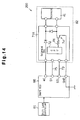
- the smart ECU 66 us connected to a solenoid ECU 71A, which controls the activation of the solenoid 41. Referring to Fig. 14, the smart ECU 66 supplies the solenoid 41 with power.
- the solenoid ECU 71A includes a CPU 72.
- the CPU 72 is connected to the base terminal of a transistor 74 via a resistor R1.
- the smart ECU 66 determines that the portable device 51 is located in the passenger compartment and activates the solenoid 41 for five seconds.
- the turning of the starter knob 22 from the ACC position to the START position is enabled.
- the engine may be started by activating a starting relay (not shown) to drive a starting motor (not shown).
- the engine starting system 11A functions as a smart ignition apparatus.
- the solenoid ECU 71A activates the solenoid 41 when the starter knob 22 is located at the ACC position as long as the vehicle is not moving. More specifically, the CPU 72 generates an activation signal in accordance with a vehicle stop signal from the shift lock controller 81 and provides the transistor 74 with the activation signal. The transistor 74 activates the solenoid 41 in response to the activation signal. This moves the plunger 42 and disengages the stopper pin 43 from the second recess 132b to enable turning of the starter knob 22. From this state, the starter knob 22 is pushed in the axial direction and then turned to the LOCK position. Subsequently, the solenoid 41 is inactivated. This engages the stopper pin 43 with the first recess 132a and prohibits turning of the starter knob 22, as shown in the state of Fig. 12. Accordingly, the engine starting system 11A functions as a key interlocking mechanism.
- the engine starting system activation restricting apparatus 200 of the second embodiment has the same advantages as those of the first embodiment.
- the determination that the vehicle is not moving may be performed based on only one of the conditions of whether the shift lever is in the parking position and whether the shift button is being pressed. Further, other conditions may be used to detect that the vehicle is not moving. For example, if a vehicle velocity sensor detects that the vehicle velocity is 0 Km/h, it may be determined that the vehicle is not moving.
- the solenoid 41 may be replaced by a motor that serves as an actuator.
- the motor has a shaft to which a pinion gear is attached.
- a rack gear, which is meshed with the pinion gear, is attached to the stopper pin 43 along the longitudinal direction of the stopper pin 43. The motor is driven to move the stopper pin 43.
- the starter knob 22 may be pulled along its axial direction.
- the stopper pin 43 may be held in a state engaged with the first projection 32a when the solenoid 41 is activated and disengaged from the first projection 32a when the solenoid 41 is inactivated.
- the shift lock controller 81 activates the solenoid 41 when detecting that the vehicle is not moving.
- the stopper pin 43 may be held in a state engaged with the first recess 132a or the second recess 132b when the solenoid 41 is activated and disengaged from the first recess 132a or the second recess 132b when the solenoid 41 is inactivated.
Landscapes
- Engineering & Computer Science (AREA)
- Mechanical Engineering (AREA)
- Chemical & Material Sciences (AREA)
- Combustion & Propulsion (AREA)
- General Engineering & Computer Science (AREA)
- Lock And Its Accessories (AREA)
Claims (17)
- Appareil permettant de limiter l'activation d'un système de démarrage du moteur d'un véhicule et prévu pour être utilisé avec un dispositif portable qui transmet un premier code d'identification, le dispositif comprenant un moyen d'actionnement (21, 22) permettant le démarrage et l'arrêt manuels du moteur et ayant une pluralité de positions d'actionnement comprenant une position de verrouillage LOCK dans laquelle le moyen de d'actionnement est verrouillé, le moyen d'actionnement comprenant un premier arrêt (32a; 132a), qui empêche le mouvement du moyen d'actionnement de la position LOCK à une autre position que la position LOCK, et un deuxième arrêt (32b, 44; 132b), qui empêche le mouvement du moyen d'actionnement à la position LOCK à partir d'une autre position que la position LOCK, un actionneur (41) permettant d'engrener le premier et le deuxième arrêts, et un moyen de commande (66, 71, 81) relié à l'actionneur pour commander l'actionneur, où :le moyen de commande assure le démarrage du moteur en désengrenant l'actionneur du premier arrêt lorsque le moyen d'actionnement est dans la position de verrouillage LOCK et le premier code d'identification envoyé en provenance du moyen du dispositif portable correspond à un deuxième code d'identification prédéterminé du moyen de commande, le dispositif étant caractérisé en ce que :le deuxième arrêt comprend une deuxième saillie (32b) et un éléments intermédiaire (44), qui est agencé entre l'actionneur et la deuxième saillie pour engrener la deuxième saillie en coopération avec l'actionneur ; etle moyen de commande assure le passage du moyen d'actionnement à la position de verrouillage LOCK en désactivant l'actionneur pour désengrener l'élément intermédiaire de la deuxième saillie lorsque le moyen d'actionnement est sur une autre position que la position de verrouillage LOCK et que le véhicule est immobile.
- Appareil selon la revendication 1, caractérisé en outre par :un moyen de commutation (45) permettant d'activer l'actionneur lorsque le moyen d'actionnement est dans une position autre que la position de verrouillage LOCK et l'actionneur étant activé par le moyen de commutation.
- Appareil selon la revendication 2, caractérisé en ce que le véhicule comporte des dispositifs électriques, et le moyen de commande comprend :un moyen de vérification du code d'identification (66) permettant de déterminer si le premier code d'identification correspond au deuxième code d'identification ; etun moyen de commande de l'actionneur (71) commandant l' actionneur ; où la pluralité des positions d'actionnement incluent une position ACC dans laquelle les dispositifs électriques du véhicule sont alimentés en énergie ; etle moyen de vérification du code d'identification et le moyen de commande de l'actionneur sont désactivés lorsque le moyen d'actionnement passe de la position LOCK à la position ACC.
- Appareil selon la revendication 3, caractérisé en ce que le moyen d'actionnement comprend une poignée (22) qui tourne autour de son axe pour déplacer le moyen d'actionnement entre la position ACC et la position LOCK, la poignée étant mobile dans sa direction axiale, et où le moyen de commutation est active mécaniquement, le dispositif comprenant également :un élément concourant (46) qui permet l'activation mécanique du moyen de commutation par un mouvement avant et arrière depuis le moyen de commutation lors de la rotation du moyen d'actionnement.
- Appareil selon la revendication 3, caractérisé en outre par :un carter (12) destiné à protéger l'actionneur, le moyen de commande de l'actionneur et le moyen de commutation.
- Appareil selon la revendication 2, caractérisé en ce que le véhicule comprend une transmission automatique munie d'un levier de vitesses mobile à une pluralité de positions, comprenant une position de stationnement et en ce que le moyen de commande détermine que le véhicule est immobile lorsque le levier de vitesses est dans la position de stationnement.
- Appareil selon la revendication 6, caractérisé en ce que le levier de vitesses est muni d'un bouton pour déplacer le levier de vitesses entre différentes positions, en ce que le moyen de commande détermine que le véhicule est immobile lorsque le levier de vitesses est dans la position de stationnement et que le bouton n'est pas enclenché.
- Appareil selon la revendication 2, caractérisé en ce que l'actionneur est un solénoïde (41) comportant une tige d'arrêt (43), engrenée avec la première saillie lorsque le solénoïde est désactivé et désengrené de la première saillie lorsque le solénoïde est activé.
- Appareil selon la revendication 1, caractérisé en ce que :le premier arrêt comprend un premier renfoncement (132a) engrené avec l'actionneur ;le deuxième arrêt comprend un deuxième renfoncement (132b) ;l'actionneur engrène le premier renfoncement et le deuxième renfoncement ; etle moyen de commande assure le passage du moyen d'actionnement sur la position LOCK en activant l'actionneur pour désengrener l'actionneur du deuxième renfoncement lorsque le moyen d'actionnement est sur une autre position que la position LOCK et que le véhicule est immobile.
- Appareil selon la revendication 9, caractérisé en ce que le véhicule comprend des dispositifs électriques et la pluralité de positions d'actionnement incluent une position ACC dans laquelle les dispositifs électriques du véhicule sont alimentés en énergie, et le moyen d'actionnement comprend une poignée (22) tournant autour de son axe pour déplacer le moyen d'actionnement entre la position ACC et la position LOCK, la poignée étant mobile dans sa direction axiale.
- Appareil selon la revendication 9, caractérisé en outre par :un moyen de commande de l'actionneur (71A) pour commander l'actionneur ; etun carter (12) destiné à protéger l'actionneur et le moyen de commande de l'actionneur.
- Appareil selon la revendication 9, caractérisé en ce que le véhicule comprend une transmission automatique munie d'un levier de vitesses mobile à une pluralité de positions, comprenant une position de stationnement, et en ce que le moyen de commande détermine que le véhicule est immobile lorsque le levier de vitesses est dans la position de stationnement.
- Appareil selon la revendication 12, caractérisé en ce que le levier de vitesses est muni d'un bouton pour déplacer le levier de vitesses entre différentes positions, et en ce que le moyen de commande détermine que le véhicule est immobile lorsque le levier de vitesses est dans la position de stationnement et que le bouton n'est pas enclenché.
- Appareil selon la revendication 9, caractérisé en ce que l'actionneur est un solénoïde (41) comportant une tige d'arrêt (43), engrené avec le premier renfoncement lorsque le solénoïde est désactivé et désengrené de la première saillie lorsque le solénoïde est activé.
- Appareil selon la revendication 1, caractérisé par un moyen de commande de verrouillage du levier de vitesses (81) relié à l'actionneur pour permettre le passage du moyen d'actionnement sur la position LOCK en désengrenant l'élément intermédiaire de la deuxième saillie lorsque le moyen d'actionnement est dans une position autre que la position LOCK et que le véhicule est immobile ; où le moyen de commande de l'actionneur assure le démarrage du moteur en désengrenant l'actionneur de la première saillie lorsque le moyen d'actionnement est dans la position LOCK et que le premier code d'identification correspond au deuxième code d'identification.
- Appareil selon la revendication 15, caractérisé en outre par : un moyen de commutation (45) permettant de relier le moyen de commande de verrouillage du levier de vitesses à l'actionneur lorsque le moyen d'actionnement est sur une autre position que la position LOCK ;
où le moyen de vérification du code d'identification et le moyen de commande de l'actionneur sont désactivés lorsque le moyen d'actionnement passe de la position LOCK sur une autre position que la position LOCK. - Appareil selon la revendication 15, caractérisé en ce que le véhicule comprend des dispositifs électriques et la pluralité de positions d'actionnement incluent une position ACC dans laquelle des dispositifs électriques du véhicule sont alimentés en énergie et une position ON dans laquelle le moteur est entraîné.
Applications Claiming Priority (4)
| Application Number | Priority Date | Filing Date | Title |
|---|---|---|---|
| JP2002156194A JP3878515B2 (ja) | 2002-05-29 | 2002-05-29 | エンジン始動装置の操作規制機構 |
| JP2002156193 | 2002-05-29 | ||
| JP2002156193A JP3908089B2 (ja) | 2002-05-29 | 2002-05-29 | エンジン始動システムの操作規制装置 |
| JP2002156194 | 2002-05-29 |
Publications (3)
| Publication Number | Publication Date |
|---|---|
| EP1378406A2 EP1378406A2 (fr) | 2004-01-07 |
| EP1378406A3 EP1378406A3 (fr) | 2004-10-20 |
| EP1378406B1 true EP1378406B1 (fr) | 2006-09-06 |
Family
ID=29720902
Family Applications (1)
| Application Number | Title | Priority Date | Filing Date |
|---|---|---|---|
| EP20030445064 Expired - Lifetime EP1378406B1 (fr) | 2002-05-29 | 2003-05-28 | Dispositif permettant de limiter l'activation du système de démarrage d'un moteur |
Country Status (5)
| Country | Link |
|---|---|
| US (2) | US7302817B2 (fr) |
| EP (1) | EP1378406B1 (fr) |
| KR (1) | KR100864033B1 (fr) |
| CN (1) | CN100339256C (fr) |
| DE (1) | DE60308101T2 (fr) |
Families Citing this family (42)
| Publication number | Priority date | Publication date | Assignee | Title |
|---|---|---|---|---|
| DE10018727A1 (de) * | 2000-04-15 | 2001-10-18 | Bayerische Motoren Werke Ag | Fernbedienbares Zündlenkschloß für Motorräder |
| DE10147031B4 (de) * | 2000-09-27 | 2012-11-29 | Marquardt Gmbh | Zündschloß für ein Kraftfahrzeug |
| JP2002308049A (ja) * | 2001-04-11 | 2002-10-23 | Tokai Rika Co Ltd | 車両用エンジン始動装置 |
| EP1378406B1 (fr) * | 2002-05-29 | 2006-09-06 | Kabushiki Kaisha Tokai Rika Denki Seisakusho | Dispositif permettant de limiter l'activation du système de démarrage d'un moteur |
| US6941779B2 (en) * | 2002-07-30 | 2005-09-13 | Kabushiki Kaisha Honda Lock | Steerage locking system for vehicle |
| JP3990224B2 (ja) * | 2002-08-09 | 2007-10-10 | 株式会社ホンダロック | ステアリングロック装置 |
| JP4100570B2 (ja) * | 2003-10-03 | 2008-06-11 | 本田技研工業株式会社 | 車両用ロック装置 |
| US7140213B2 (en) * | 2004-02-21 | 2006-11-28 | Strattec Security Corporation | Steering column lock apparatus and method |
| DE102004019919B3 (de) * | 2004-04-21 | 2006-02-02 | Huf Hülsbeck & Fürst Gmbh & Co. Kg | Vorrichtung zum Starten eines Fahrzeugmotors mittels eines elektronischen Schlüssels und ein dazu zu verwendener Schlüssel |
| DE102005002018A1 (de) * | 2005-01-15 | 2006-07-20 | Marquardt Gmbh | Zündschloß für ein Kraftfahrzeug |
| US20060220458A1 (en) * | 2005-04-05 | 2006-10-05 | Feldman Mark G | Keyless ignition module for an automotive vehicle |
| KR100851139B1 (ko) * | 2005-12-09 | 2008-08-08 | 현대자동차주식회사 | 스티어링컬럼록장치의 키인터록장치 |
| US7730752B2 (en) * | 2006-03-13 | 2010-06-08 | Kawasaki Jukogyo Kabushiki Kaisha | Theft prevention apparatus for leisure vehicle |
| US20090199604A1 (en) * | 2006-06-07 | 2009-08-13 | Eung Lyul Kim | Steering lock device for coupling electronic identification system and method of manufacturing thereof |
| WO2008137575A1 (fr) * | 2007-05-03 | 2008-11-13 | Jonathon Hocut | Serrure américaine résistante aux bosses |
| KR100820859B1 (ko) * | 2007-07-31 | 2008-04-11 | 양재우 | 차량 보안을 위한 전자 키 구조 |
| KR100921048B1 (ko) * | 2007-12-15 | 2009-10-08 | 현대자동차주식회사 | 스마트키 시스템을 탑재한 차량의 변속레버 잠금장치 |
| JP5038238B2 (ja) * | 2008-06-12 | 2012-10-03 | 株式会社東海理化電機製作所 | 車両機能制限システム |
| JP5296470B2 (ja) * | 2008-09-24 | 2013-09-25 | 株式会社東海理化電機製作所 | 車内補助キーのキー保持装置 |
| KR100986462B1 (ko) * | 2008-11-28 | 2010-10-08 | 기아자동차주식회사 | 자동차의 키 인터록 |
| JP5118078B2 (ja) * | 2009-02-03 | 2013-01-16 | 株式会社東海理化電機製作所 | キー規制装置 |
| JP5118079B2 (ja) * | 2009-02-03 | 2013-01-16 | 株式会社東海理化電機製作所 | キー装置 |
| KR101094910B1 (ko) * | 2009-10-30 | 2011-12-16 | 기아자동차주식회사 | 차량의 키 인터록 장치 |
| JP5394981B2 (ja) * | 2010-05-13 | 2014-01-22 | 株式会社東海理化電機製作所 | イグニッションスイッチの操作規制装置 |
| JP5431250B2 (ja) * | 2010-06-08 | 2014-03-05 | 株式会社東海理化電機製作所 | キーインターロック装置 |
| FR2965230B1 (fr) * | 2010-09-28 | 2020-02-28 | U-Shin France Sas | Antivol de direction pour vehicule automobile |
| JP5611752B2 (ja) * | 2010-10-07 | 2014-10-22 | 株式会社東海理化電機製作所 | イグニッションスイッチの操作規制装置 |
| US8587147B2 (en) | 2012-02-17 | 2013-11-19 | Johnson Industries, Inc. | Safety system |
| US9261234B2 (en) | 2012-02-17 | 2016-02-16 | Johnson Industries, Inc. | Safety system |
| CN102797842A (zh) * | 2012-08-30 | 2012-11-28 | 黄山市汽车电器股份公司 | 一种点火开关防误操作结构 |
| DE202013009915U1 (de) * | 2012-12-03 | 2014-05-13 | Strattec Security Corporation | Zündschloss-Lenkschloss-Anordnung |
| CN103935322A (zh) * | 2013-01-23 | 2014-07-23 | 长春易控汽车电子有限公司 | 汽车的密码防盗方法 |
| LU92228B1 (de) * | 2013-06-20 | 2014-12-22 | Iee Sarl | Heizfähiges Innenraumverkleidungselement |
| FR3007571B1 (fr) * | 2013-06-20 | 2015-06-19 | Shin France U | Actionneur electromecanique et procede d'utilisation de cet actionneur electromecanique |
| FR3012094B1 (fr) * | 2013-10-21 | 2016-01-01 | Shin France U | Antivol pour colonne de direction de vehicule automobile |
| DE102015108664A1 (de) | 2014-05-30 | 2015-12-03 | Huf Hülsbeck & Fürst Gmbh & Co. Kg | Schließzylinder mit Rückstellsperre |
| JP6042459B2 (ja) * | 2015-01-07 | 2016-12-14 | 株式会社東海理化電機製作所 | キーシリンダ装置 |
| JP6471105B2 (ja) * | 2016-01-14 | 2019-02-13 | 株式会社東海理化電機製作所 | ステアリングロック装置、及びステアリングロック装置の組立方法 |
| JP6166427B1 (ja) * | 2016-06-02 | 2017-07-19 | 株式会社東海理化電機製作所 | ステアリングロック装置 |
| EP3339110B1 (fr) * | 2016-12-22 | 2020-02-05 | Asahi Denso Co., Ltd. | Dispositif de démarrage de moteur |
| JP6851044B2 (ja) * | 2016-12-22 | 2021-03-31 | 朝日電装株式会社 | エンジン始動装置 |
| US10501050B2 (en) * | 2017-06-30 | 2019-12-10 | GM Global Technology Operations LLC | Vehicle ignition system |
Family Cites Families (30)
| Publication number | Priority date | Publication date | Assignee | Title |
|---|---|---|---|---|
| FR2288651A1 (fr) * | 1974-03-05 | 1976-05-21 | Neiman Exploit Des Brevets | Dispositif antivol de securite destine aux vehicules equipes d'un moteur diesel |
| JPS5825759A (ja) | 1981-08-07 | 1983-02-16 | Hitachi Ltd | 2次元符号化k値自動切替方式 |
| JPS5871236A (ja) | 1981-10-22 | 1983-04-27 | Toyota Motor Corp | 車両用イグニツシヨンスイツチ装置 |
| FR2569641B1 (fr) * | 1984-08-31 | 1991-05-03 | Kiekert Gmbh Co Kg | Dispositif de securite contre l'utilisation non autorisee d'un vehicule automobile |
| JP2685185B2 (ja) * | 1987-07-21 | 1997-12-03 | 日産自動車株式会社 | ステアリングロック装置 |
| DE4019478A1 (de) * | 1989-06-20 | 1991-01-10 | Honda Motor Co Ltd | Elektrische spannungsversorgungs-kontrolleinheit fuer ein kraftfahrzeug |
| DE4037918C1 (en) * | 1990-11-29 | 1991-11-07 | Bayerische Motoren Werke Ag, 8000 Muenchen, De | Vehicle steering-ignition lock - has stop fixed to key cylinder which contacts lock element to prevent movement unless operated by correct key |
| US5685183A (en) * | 1994-07-19 | 1997-11-11 | Kabushiki Kaisha Tokai Rika Denki Seisakusho | Vehicle locking device |
| EP0742127B1 (fr) * | 1995-04-11 | 2002-09-11 | Tokai Rika Co., Ltd. | Dispositif de commande de démarrage pour un véhicule |
| JP3580923B2 (ja) * | 1995-12-21 | 2004-10-27 | 株式会社日本自動車部品総合研究所 | 盗難防止装置 |
| JP3708296B2 (ja) * | 1996-08-09 | 2005-10-19 | 万能工業株式会社 | コラムat用シフトレバー装置のシフトロック機構 |
| JPH10236280A (ja) | 1997-03-03 | 1998-09-08 | Yazaki Corp | 車両用icカード、icカードを用いたイグニッションスイッチ装置、およびステアリングロック装置 |
| JPH10315914A (ja) * | 1997-05-19 | 1998-12-02 | Tokai Rika Co Ltd | 車両用始動装置 |
| JP3142508B2 (ja) | 1997-07-23 | 2001-03-07 | トヨタ自動車株式会社 | 車両電子キー装置 |
| AU7628398A (en) * | 1997-09-12 | 1999-03-25 | Robert Bosch Gmbh | An ignition lock system |
| DE19821899C2 (de) * | 1998-05-15 | 2001-06-13 | Siemens Ag | Drehschalter, insbesondere Zündanlaßschalter |
| JP3657137B2 (ja) | 1999-02-05 | 2005-06-08 | 富士重工業株式会社 | エンジン始動装置 |
| JP3688923B2 (ja) * | 1999-02-09 | 2005-08-31 | 株式会社東海理化電機製作所 | シフトレバー装置 |
| JP4028117B2 (ja) * | 1999-02-09 | 2007-12-26 | 株式会社東海理化電機製作所 | キーロック装置 |
| JP3938822B2 (ja) * | 1999-07-07 | 2007-06-27 | 株式会社東海理化電機製作所 | シフトレバー装置 |
| DE19942485A1 (de) * | 1999-09-07 | 2001-04-05 | Bosch Gmbh Robert | Kraftfahrzeug-Türschliesssystem mit Passive Entry-Funktion und Schnellentriegelung |
| DE19951986C1 (de) * | 1999-10-28 | 2001-08-09 | Huf Huelsbeck & Fuerst Gmbh | Elektronischer Zündanlassschalter für Kraftfahrzeuge |
| JP3924416B2 (ja) | 2000-04-25 | 2007-06-06 | 株式会社東海理化電機製作所 | 車両用エンジン始動装置 |
| DE10126129B4 (de) * | 2000-05-31 | 2011-06-01 | Kabushiki Kaisha Tokai Rika Denki Seisakusho | Schaltgerät für Fahrzeuge |
| JP2002067880A (ja) * | 2000-08-31 | 2002-03-08 | Tokai Rika Co Ltd | インターロックの緊急解除構造 |
| US6516640B2 (en) * | 2000-12-05 | 2003-02-11 | Strattec Security Corporation | Steering column lock apparatus and method |
| JP3851803B2 (ja) * | 2001-02-09 | 2006-11-29 | 株式会社東海理化電機製作所 | 電子式車両盗難防止装置 |
| JP2002308049A (ja) * | 2001-04-11 | 2002-10-23 | Tokai Rika Co Ltd | 車両用エンジン始動装置 |
| JP3838630B2 (ja) * | 2002-02-27 | 2006-10-25 | 株式会社ホンダロック | 車両用エンジン始動装置 |
| EP1378406B1 (fr) * | 2002-05-29 | 2006-09-06 | Kabushiki Kaisha Tokai Rika Denki Seisakusho | Dispositif permettant de limiter l'activation du système de démarrage d'un moteur |
-
2003
- 2003-05-28 EP EP20030445064 patent/EP1378406B1/fr not_active Expired - Lifetime
- 2003-05-28 DE DE2003608101 patent/DE60308101T2/de not_active Expired - Lifetime
- 2003-05-28 US US10/446,469 patent/US7302817B2/en not_active Expired - Fee Related
- 2003-05-28 KR KR1020030034174A patent/KR100864033B1/ko not_active Expired - Fee Related
- 2003-05-29 CN CNB031406351A patent/CN100339256C/zh not_active Expired - Fee Related
-
2007
- 2007-06-22 US US11/767,133 patent/US20080041128A1/en not_active Abandoned
Also Published As
| Publication number | Publication date |
|---|---|
| DE60308101D1 (de) | 2006-10-19 |
| EP1378406A3 (fr) | 2004-10-20 |
| CN100339256C (zh) | 2007-09-26 |
| CN1478683A (zh) | 2004-03-03 |
| DE60308101T2 (de) | 2007-05-10 |
| US20040003632A1 (en) | 2004-01-08 |
| US7302817B2 (en) | 2007-12-04 |
| KR20030093124A (ko) | 2003-12-06 |
| EP1378406A2 (fr) | 2004-01-07 |
| KR100864033B1 (ko) | 2008-10-16 |
| US20080041128A1 (en) | 2008-02-21 |
Similar Documents
| Publication | Publication Date | Title |
|---|---|---|
| EP1378406B1 (fr) | Dispositif permettant de limiter l'activation du système de démarrage d'un moteur | |
| EP1445158B1 (fr) | Interrupteur-démarreur d'un moteur | |
| EP1520757B1 (fr) | Dispositif de verrouillage d'un véhicule | |
| US6756698B2 (en) | Switch device for vehicle | |
| US20060236970A1 (en) | Control system for vehicle | |
| US7199710B2 (en) | Controller for remote control system | |
| JP2009143528A (ja) | 車両の変速レバーロック装置 | |
| US6380642B1 (en) | Method for starting a motor vehicle and ignition-starter device | |
| JP3851802B2 (ja) | 電子式車両盗難防止装置 | |
| US7009479B1 (en) | Steering column lock for personal identification card system | |
| US7501714B2 (en) | Engine starting system | |
| US7011377B2 (en) | Electronic control unit for automatically activating a parking brake and method for preventing the automatic activation of the parking brake in motor vehicles | |
| JP3885022B2 (ja) | 車両用盗難防止装置 | |
| JP4144741B2 (ja) | 車両の盗難防止装置 | |
| JP3878515B2 (ja) | エンジン始動装置の操作規制機構 | |
| CN100464065C (zh) | 发动机起动·停止控制系统 | |
| JP2003341477A (ja) | エンジン始動システムの操作規制装置 | |
| JP4199582B2 (ja) | 電子式ステアリングロック装置 | |
| EP0893316B1 (fr) | Dispositif antivol pour vehicules | |
| JP3379888B2 (ja) | 車両用盗難防止装置 | |
| JP4056422B2 (ja) | ステアリングロック装置の安全装置 | |
| JP6533152B2 (ja) | ステアリングロック装置 | |
| JP3990038B2 (ja) | 車両用盗難防止装置 | |
| JP2563128Y2 (ja) | 車両用盗難防止装置 | |
| JP2010125904A (ja) | エンジンの始動制御装置 |
Legal Events
| Date | Code | Title | Description |
|---|---|---|---|
| PUAI | Public reference made under article 153(3) epc to a published international application that has entered the european phase |
Free format text: ORIGINAL CODE: 0009012 |
|
| AK | Designated contracting states |
Kind code of ref document: A2 Designated state(s): AT BE BG CH CY CZ DE DK EE ES FI FR GB GR HU IE IT LI LU MC NL PT RO SE SI SK TR |
|
| AX | Request for extension of the european patent |
Extension state: AL LT LV MK |
|
| PUAL | Search report despatched |
Free format text: ORIGINAL CODE: 0009013 |
|
| AK | Designated contracting states |
Kind code of ref document: A3 Designated state(s): AT BE BG CH CY CZ DE DK EE ES FI FR GB GR HU IE IT LI LU MC NL PT RO SE SI SK TR |
|
| AX | Request for extension of the european patent |
Extension state: AL LT LV MK |
|
| RIC1 | Information provided on ipc code assigned before grant |
Ipc: 7B 60R 25/02 B Ipc: 7B 60R 25/04 A |
|
| 17P | Request for examination filed |
Effective date: 20041126 |
|
| 17Q | First examination report despatched |
Effective date: 20050318 |
|
| AKX | Designation fees paid |
Designated state(s): DE FR GB SE |
|
| GRAP | Despatch of communication of intention to grant a patent |
Free format text: ORIGINAL CODE: EPIDOSNIGR1 |
|
| GRAS | Grant fee paid |
Free format text: ORIGINAL CODE: EPIDOSNIGR3 |
|
| GRAA | (expected) grant |
Free format text: ORIGINAL CODE: 0009210 |
|
| AK | Designated contracting states |
Kind code of ref document: B1 Designated state(s): DE FR GB SE |
|
| REG | Reference to a national code |
Ref country code: GB Ref legal event code: FG4D |
|
| REF | Corresponds to: |
Ref document number: 60308101 Country of ref document: DE Date of ref document: 20061019 Kind code of ref document: P |
|
| REG | Reference to a national code |
Ref country code: SE Ref legal event code: TRGR |
|
| ET | Fr: translation filed | ||
| PLBE | No opposition filed within time limit |
Free format text: ORIGINAL CODE: 0009261 |
|
| STAA | Information on the status of an ep patent application or granted ep patent |
Free format text: STATUS: NO OPPOSITION FILED WITHIN TIME LIMIT |
|
| 26N | No opposition filed |
Effective date: 20070607 |
|
| PGFP | Annual fee paid to national office [announced via postgrant information from national office to epo] |
Ref country code: FR Payment date: 20110523 Year of fee payment: 9 Ref country code: SE Payment date: 20110512 Year of fee payment: 9 |
|
| PGFP | Annual fee paid to national office [announced via postgrant information from national office to epo] |
Ref country code: GB Payment date: 20110525 Year of fee payment: 9 |
|
| PGFP | Annual fee paid to national office [announced via postgrant information from national office to epo] |
Ref country code: DE Payment date: 20110525 Year of fee payment: 9 |
|
| REG | Reference to a national code |
Ref country code: SE Ref legal event code: EUG |
|
| GBPC | Gb: european patent ceased through non-payment of renewal fee |
Effective date: 20120528 |
|
| PG25 | Lapsed in a contracting state [announced via postgrant information from national office to epo] |
Ref country code: SE Free format text: LAPSE BECAUSE OF NON-PAYMENT OF DUE FEES Effective date: 20120529 |
|
| REG | Reference to a national code |
Ref country code: FR Ref legal event code: ST Effective date: 20130131 |
|
| REG | Reference to a national code |
Ref country code: DE Ref legal event code: R119 Ref document number: 60308101 Country of ref document: DE Effective date: 20121201 |
|
| PG25 | Lapsed in a contracting state [announced via postgrant information from national office to epo] |
Ref country code: FR Free format text: LAPSE BECAUSE OF NON-PAYMENT OF DUE FEES Effective date: 20120531 Ref country code: GB Free format text: LAPSE BECAUSE OF NON-PAYMENT OF DUE FEES Effective date: 20120528 |
|
| PG25 | Lapsed in a contracting state [announced via postgrant information from national office to epo] |
Ref country code: DE Free format text: LAPSE BECAUSE OF NON-PAYMENT OF DUE FEES Effective date: 20121201 |