EP0300913B1 - Vorrichtung zum Glätten, Verdichten und/oder Abkratzen, insbesondere für die Ränder von Strassendeckenschichten - Google Patents
Vorrichtung zum Glätten, Verdichten und/oder Abkratzen, insbesondere für die Ränder von Strassendeckenschichten Download PDFInfo
- Publication number
- EP0300913B1 EP0300913B1 EP88401898A EP88401898A EP0300913B1 EP 0300913 B1 EP0300913 B1 EP 0300913B1 EP 88401898 A EP88401898 A EP 88401898A EP 88401898 A EP88401898 A EP 88401898A EP 0300913 B1 EP0300913 B1 EP 0300913B1
- Authority
- EP
- European Patent Office
- Prior art keywords
- scraper
- frame
- strip
- transverse
- displacement
- Prior art date
- Legal status (The legal status is an assumption and is not a legal conclusion. Google has not performed a legal analysis and makes no representation as to the accuracy of the status listed.)
- Expired - Lifetime
Links
- 238000009499 grossing Methods 0.000 title claims abstract description 39
- 238000007790 scraping Methods 0.000 title claims abstract description 25
- 239000000463 material Substances 0.000 claims abstract description 47
- 238000006073 displacement reaction Methods 0.000 claims abstract description 46
- 239000011324 bead Substances 0.000 claims abstract description 31
- 238000005259 measurement Methods 0.000 claims abstract description 4
- 239000000523 sample Substances 0.000 claims description 27
- 230000015572 biosynthetic process Effects 0.000 claims description 10
- 238000002360 preparation method Methods 0.000 claims description 10
- 230000007246 mechanism Effects 0.000 claims description 8
- 229910052751 metal Inorganic materials 0.000 claims description 8
- 239000002184 metal Substances 0.000 claims description 8
- 230000000903 blocking effect Effects 0.000 claims description 7
- 238000010168 coupling process Methods 0.000 claims description 5
- 238000005859 coupling reaction Methods 0.000 claims description 5
- 230000008878 coupling Effects 0.000 claims description 4
- 238000013459 approach Methods 0.000 claims description 3
- 125000004122 cyclic group Chemical group 0.000 claims description 3
- 238000001514 detection method Methods 0.000 claims description 3
- 239000012530 fluid Substances 0.000 claims description 3
- 238000007789 sealing Methods 0.000 claims description 3
- 239000000700 radioactive tracer Substances 0.000 claims 3
- 230000009977 dual effect Effects 0.000 abstract 1
- 239000011248 coating agent Substances 0.000 description 16
- 238000000576 coating method Methods 0.000 description 16
- 238000005056 compaction Methods 0.000 description 8
- 238000010276 construction Methods 0.000 description 4
- 239000010410 layer Substances 0.000 description 4
- 230000000717 retained effect Effects 0.000 description 4
- 229910000831 Steel Inorganic materials 0.000 description 3
- 239000010959 steel Substances 0.000 description 3
- 230000009471 action Effects 0.000 description 2
- 230000008901 benefit Effects 0.000 description 2
- 238000009434 installation Methods 0.000 description 2
- 238000000034 method Methods 0.000 description 2
- 229910052782 aluminium Inorganic materials 0.000 description 1
- XAGFODPZIPBFFR-UHFFFAOYSA-N aluminium Chemical compound [Al] XAGFODPZIPBFFR-UHFFFAOYSA-N 0.000 description 1
- 238000004873 anchoring Methods 0.000 description 1
- 239000010426 asphalt Substances 0.000 description 1
- 238000005452 bending Methods 0.000 description 1
- 230000015556 catabolic process Effects 0.000 description 1
- 238000006731 degradation reaction Methods 0.000 description 1
- 230000006866 deterioration Effects 0.000 description 1
- 230000000694 effects Effects 0.000 description 1
- 230000002349 favourable effect Effects 0.000 description 1
- 238000003780 insertion Methods 0.000 description 1
- 230000037431 insertion Effects 0.000 description 1
- 230000007774 longterm Effects 0.000 description 1
- 238000012423 maintenance Methods 0.000 description 1
- 230000008439 repair process Effects 0.000 description 1
- 230000001846 repelling effect Effects 0.000 description 1
- 238000000926 separation method Methods 0.000 description 1
- 230000007480 spreading Effects 0.000 description 1
- 239000002344 surface layer Substances 0.000 description 1
- 239000000725 suspension Substances 0.000 description 1
- 238000012546 transfer Methods 0.000 description 1
- 238000002604 ultrasonography Methods 0.000 description 1
- XLYOFNOQVPJJNP-UHFFFAOYSA-N water Substances O XLYOFNOQVPJJNP-UHFFFAOYSA-N 0.000 description 1
- 239000002023 wood Substances 0.000 description 1
Images




Classifications
-
- E—FIXED CONSTRUCTIONS
- E01—CONSTRUCTION OF ROADS, RAILWAYS, OR BRIDGES
- E01C—CONSTRUCTION OF, OR SURFACES FOR, ROADS, SPORTS GROUNDS, OR THE LIKE; MACHINES OR AUXILIARY TOOLS FOR CONSTRUCTION OR REPAIR
- E01C19/00—Machines, tools or auxiliary devices for preparing or distributing paving materials, for working the placed materials, or for forming, consolidating, or finishing the paving
- E01C19/48—Machines, tools or auxiliary devices for preparing or distributing paving materials, for working the placed materials, or for forming, consolidating, or finishing the paving for laying-down the materials and consolidating them, or finishing the surface, e.g. slip forms therefor, forming kerbs or gutters in a continuous operation in situ
-
- E—FIXED CONSTRUCTIONS
- E01—CONSTRUCTION OF ROADS, RAILWAYS, OR BRIDGES
- E01C—CONSTRUCTION OF, OR SURFACES FOR, ROADS, SPORTS GROUNDS, OR THE LIKE; MACHINES OR AUXILIARY TOOLS FOR CONSTRUCTION OR REPAIR
- E01C19/00—Machines, tools or auxiliary devices for preparing or distributing paving materials, for working the placed materials, or for forming, consolidating, or finishing the paving
-
- E—FIXED CONSTRUCTIONS
- E01—CONSTRUCTION OF ROADS, RAILWAYS, OR BRIDGES
- E01C—CONSTRUCTION OF, OR SURFACES FOR, ROADS, SPORTS GROUNDS, OR THE LIKE; MACHINES OR AUXILIARY TOOLS FOR CONSTRUCTION OR REPAIR
- E01C2301/00—Machine characteristics, parts or accessories not otherwise provided for
- E01C2301/20—Screed or paver accessories for paving joint or edge treatment
Definitions
- the present invention relates to a smoothing, compacting and / or scraping device, intended to form a longitudinal bead of a material, for example granular, powdery and / or viscous, previously spread out along a longitudinal strip of limited width on a substantially flat surface. , and / or to smooth and compact at least one edge, generally inclined on said substantially flat surface, of said longitudinal strip of material.
- the invention relates in particular to a smoothing, compacting and / or scraping device arranged in public works equipment or vehicle, or associated with such equipment or vehicle, and in particular to a device of this type, advantageously with automatic control, intended on the one hand, for the preparation of a longitudinal connection joint between two strips of road surfacing, and, on the other hand, for smoothing and compacting at least one free and possibly inclined edge of strips of road surfacing.
- the device according to the invention can be used in a large number of different applications, it will be described in the rest of this specification only in the context of its application to the preparation of a road surface joint and / or to the smoothing and compacting an inclined free edge of such a coating, because it is in this application that the device according to the invention seems to be of greatest interest.
- the smoothing, compacting and / or scraping device is presented as an accessory mounted laterally on the rear of the chassis of a machine of well-known structure and particularly arranged to be used for making or repairing roadways. , and more specifically for laying the covering strips constituting the wearing course of the roadways.
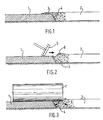
- FIG. 1 schematically represents, in partial cross section, a road at the level of the connection of two adjacent traffic lanes .
- the paver is first of all moved longitudinally on a lane of the road, in order to lay a first covering strip 1, made of bituminous or coated concrete of any suitable nature, which corresponds to the width of this lane.
- a second covering strip 2 is produced, which corresponds to the width of the or a second lane of the road, adjacent to the first lane, in moving the finisher on this second track, so that there is a marginal overlap 3 of the first strip laid 1, along its edge 4 adjacent to the second strip 2, by hot coating material of this second strip 2 , this covering 3 being limited for example to a width of 5 to 10 cm and to a thickness of 0.5 to 1 cm.
- This technique of installing the covering of the wearing course in successively deposited adjacent strips allows, by concentrating the passage vehicles on the track (s) on which the laying of the corresponding covering strip is not in progress, to practice alternating traffic, and therefore not to interrupt traffic on a stretch of road under construction. This is all the more important since the majority of road works currently carried out concern the maintenance and repair of roadways.
- the new coating of a road which restores its comfort and safety characteristics, is also essential for the long-term performance of the structure of the road as a whole, and must in particular ensure a good seal for the lower layers.
- the material of the marginal covering 3 is pushed manually from the first strip laid 1 onto the second strip 2, which has just been laid, by one or two workers working behind the paver, and which operate squeegees 5 so as to form, as shown in FIG. 2, a longitudinal bead 6 of material still hot on the second laid strip 2.
- This bead 6 should ideally be a short distance from the adjacent edge 4 of the first laid strip 1, so that, by the compacting operation which follows the preparation of the bead 6, the joint is well made.
- the inclined and free edges of the covering strips laid that is to say the inclined edges like the edge 4 in FIG. 1, but by which the covering strips considered are not or not yet adjacent to a other covering strip, and which in particular constitute the edges of the pavement covering, are currently smoothed and compacted by the passage of self-propelled compacting machines.
- These machines also called compactors, move, using wheels fitted with tires, behind the paver, on the covering strip laid by the latter and along the free edge of this strip.
- These compactors are equipped with a smoothing and lateral compacting device, comprising a wheel mounted on a transverse axis with respect to the longitudinal direction of the edge considered, and integral with an articulated mechanism for raising and lowering the wheel, and orientation of its axis around a horizontal and longitudinal pivot. So the side wheel can be lowered, so that its tread is applied against the inclined surface of the free edge of the covering strip, which makes it possible to ensure both smoothing and compacting of this inclined surface by the longitudinal displacement of the side wheel with the compactor which supports it.
- a smoothing and lateral compacting device comprising a wheel mounted on a transverse axis with respect to the longitudinal direction of the edge considered, and integral with an articulated mechanism for raising and lowering the wheel, and orientation of its axis around a horizontal and longitudinal pivot. So the side wheel can be lowered, so that its tread is applied against the inclined surface of the free edge of the covering strip, which makes it possible to ensure both smoothing and compacting of this inclined surface by the longitudinal displacement of the side wheel with the
- This smoothing and compacting device the lateral wheel of which allows a force with a large horizontal component to be maintained on the edge of the coating strip, by fulfilling the function of a lateral stop, in the absence of such a naturally constituted stop. by a shoulder or a strip of coating adjacent to the road, is a very useful device for the compaction of mixes for surface courses or relatively easy to handle bitumen, and laid in strips of coating, because it prevents their lateral creep at the level of longitudinal and free edges of the strips laid, and therefore the vertical deformations deforming the transverse profile of said covering strips.
- the smoothing and compacting side wheel is driven by a self-propelled vehicle traveling on the covering strip which has just been laid by the finisher, it is imperative that this vehicle be kept at a sufficiently large distance behind the finisher, so that the installed strip is sufficiently cooled to the point of being able to support the weight of the vehicle without being damaged by the passage of the latter.
- the side wheel can exert its smoothing and compacting action on the inclined surface of the edge of the strip only at such a sufficiently large distance behind the finisher, so that the effectiveness of its intervention is thereby is considerably reduced, because, of course, it is in the hottest state, that is to say just behind the finisher, that the material of the laid strip is most likely to creep, in particular laterally.
- the invention relates to a device for smoothing, compacting and / or scraping , advantageously integral with the finisher, making it possible to constitute and suitably position a bead of coating material necessary for making an excellent longitudinal connection joint, and / or to smooth and compact at least one free edge of a strip of this material with greater efficiency and closer after the installation of this strip.
- the invention proposes a device which is congruent with the aim of bringing the covering material deposited at the joint on the first previously laid band onto the second band laid, in order to produce the connection joint between the two bands, and / or to apply a lateral stop in an adjustable position and with an adjustable pressure against at least one free edge of a laid strip, in order to smooth and compact it.
- a device for finishing pavements and intended to compact the lateral edge of a covering strip is intended to be suspended from a finisher, and it comprises a vibrating plate extending substantially horizontally and associated with a vibration generator, as well as a pressure plate, mounted on one side of the vibrating plate in forming an angle with it and being inclined downwards.
- the pressure plate is connected to the vibrating plate by means of a carrier plate articulated on the vibrating plate. In this way, the angular position of the pressure plate relative to the vibrating plate is adjustable. This adjustment is ensured by means of a jack.
- the pressure plate can slide from top to bottom along the carrier plate, and it can in particular be retracted in the maximum position upwards, so as to adjust the length of this pressure plate which projects under the vibrating plate. It is thus possible to adjust the depth and the angle of intervention of this pressure plate on the edge of the coating strip to be compacted.
- the device proposed by this document is in no way provided with a structure which makes the two applications mentioned above indifferent.
- the device comprises a scraper blade which can be brought into contact with the material constituting the covering, in order to deposit this material in the form of a harmless or a bead along the joint, and this scraper blade cooperates with a rotary brush displaceable longitudinally along the bead to level it off as well as to sweep the material coming from the joint and to move it laterally on the surface of the second layer of coating deposited.
- the invention proposes, for its part, a device making it possible to obtain well-differentiated phases of transverse and vertical displacement of the scraper relative to the chassis.
- the smoothing, compacting and / or scraping device in particular for smoothing and compacting at least one free edge of a strip of road surface that has just been laid, and / or the preparation of a longitudinal connection joint between two strips of road surface, one of which has been laid before the other, which is laid substantially along the first strip laid and with a limited marginal overlap of the first strip laid by coating material of the second strip, using at least one machine, such as a finisher, behind which said device is intended to operate, comprises:
- a scraper intended to scrape against a free edge of a laid strip in order to smooth and compact it or against the first laid strip, in order to bring the coating material which covers it over the second strip, so as to form on this last a longitudinal bead of covering material, intended to be subsequently compacted into a longitudinal connection joint, and
- Connecting means which connect the scraper to the chassis, and allow vertical and transverse movements of the scraper with respect respectively to the chassis and to its direction of movement
- this device being characterized in that it also comprises actuation means, the means for connecting and actuating the scraper comprising at least one member for reciprocating transverse displacement of the scraper with respect to the chassis and at least one member for reciprocating vertical displacement of the scraper with respect to the chassis.
- This smoothing, compacting and / or scraping device can be made as a machine or an autonomous machine, and its chassis can be provided with wheels and propulsion means, so that it can be moved longitudinally behind the paver.
- the chassis of said device is secured to the rear of the table of a finisher, and the scraper and the connection and actuation means are removably mounted on the chassis, so that the scraper is always protruding sideways on one side or the other of the paver table with respect to its direction of travel.
- connection and actuation means in the form of essentially mechanical means, directly or indirectly driven by power draw necessary on the finisher, and thus benefiting from the assurance respectively of smoothing and compacting a free edge of a laid strip while the material of this strip is in a state conducive to creep, and of forming a bead immediately after laying of the second strip and of the covering of the first strip, that is to say when the covering material is in the best conditions to be brought back onto the second strip laid.
- connection and actuation means also and advantageously comprise at least one member for orienting the scraper with respect to the direction of movement of the chassis.
- the means for actuating the scraper relative to the chassis are advantageously controlled according to a sequential operating cycle by a sequencer or a programmable controller, in order to ensure good regularity in the formation of the bead.
- At least one of the vertical, transverse and / or orientation, but preferably each of them, comprises at least one double-acting cylinder, preferably with operating fluid.
- This jack can be an electro-mechanical jack, for example with a screw driven by an electric motor, but, preferably, it is a pneumatic jack, or, advantageously, a hydraulic jack.
- the latter may advantageously comprise a substantially straight scraper blade having, substantially in its central part, a pivot with a substantially vertical axis by which it is pivotally mounted around the axis of the pivot, on a part, movable relative to the chassis, of one of the vertical or transverse displacement members.
- the orientation member is a tilt cylinder articulated, on the one hand, on the scraper blade, at least about an axis parallel to the axis of the pivot of the blade and spaced apart of this pivot, preferably rearward relative to the direction of movement of the chassis, so as not to interfere with the latter or with the frame of the finisher, and, on the other hand, on the vertical or transverse displacement member on which the scraper blade is pivotally mounted.
- the member for orienting the scraper with respect to the direction of movement of the chassis may, in a simpler embodiment, but allowing only a limited number of different orientations of the scraper to be adopted, comprise a support integral with the scraper and having means for pivoting around a substantially vertical axis on a part movable relative to the chassis of one of the vertical or transverse displacement members as well as several holes, spaced on an arc of a circle centered on the substantially vertical axis of said pivot means, and each of which can be selectively disposed opposite a hole drilled in said movable part of the vertical or transverse movement, in order to receive a locking pin for the squeegee support in a determined angular position relative to this movable part.
- the transverse displacement member comprises an extensible arm on which is substantially axially mounted at least one extension-retraction cylinder of the extensible arm, which comprises at least two sections mounted axially sliding with respect to each other, one of which is a section attached to the chassis and to which an extension-retraction cylinder is itself attached, the cylinder or cylinders controlling the movements, by compared to this section, another section of the extendable arm which supports the scraper laterally cantilevered outside the section attached to the chassis.
- the device comprises a single extension-retraction cylinder, which is mounted in the extendable arm, which is a telescopic arm whose sections respectively attached to the chassis and supporting the scraper are substantially coaxial and telescopically mounted. by sliding at least part of one into the other.
- the device comprises two extension-retraction jacks, mounted in series, one in the extension of the other, and one of which is an approach and / or overall transverse positioning cylinder, which is housed in the section of the extendable or telescopic arm attached to the chassis, this cylinder itself being attached to the chassis, and the other cylinder of which is an alternative transverse drive cylinder of the section of the extendable or telescopic arm supporting the scraper, on a cyclic transverse stroke formation of a bead by the scraper.
- the vertical movements of the scraper are very simply ensured by the fact that the section of the extendable arm attached to the chassis is pivotally mounted on the latter, around an axis not perpendicular to the direction of movement of the chassis, and the the extendable arm is articulated, at a point distant from its pivot axis on the chassis, on the vertical displacement member which is itself a jack articulated moreover on the chassis, to control the pivotings of the extendable arm relative to the chassis .
- the section of the latter which supports the scraper preferably has an end portion which is always cantilevered with respect to the other or to the other sections of the extendable arm, and which is provided with a light through which the tilting cylinder passes, when the member tilt is such a jack.
- the means of connection and actuation are further pivoted on the chassis around a substantially vertical axis and connected to the chassis by a safety mechanism.
- This safety mechanism advantageously comprises at least one deformable connecting member over a limited rearward travel, at least one elastic return member of the connecting and actuating means to an initial position around said substantially vertical pivot axis on the chassis, and at least one actuator of a position detector controlling the operation of the member for vertical displacement of the connecting and actuating means, so that any possible blocking of the advance of the scraper against an obstacle is followed by a retraction backwards and upwards of this scraper, to disengage from the obstacle.
- this safety mechanism comprises at least one flexible metal blade, simultaneously constituting a deformable connecting member, an elastic return member and an actuator of the position detector, each flexible metal blade being fixed , on the one hand, to the chassis and, on the other hand, to the connection and actuation means, and bearing against a probe of the position detector at least after a certain rotation of the connection and actuation means towards the rear, around the substantially vertical pivot axis on the chassis.
- the scraper is rotated backwards and then lifted, and can thus escape the obstacle opposing the continuation of its advance with the chassis and the finisher, without it being damaged, and the scraper can then return to its working position.
- the paver is a machine on which a hydraulic power circuit is generally provided for the specific needs of the paver, it is very advantageous, to make the most of the presence of this hydraulic circuit, that the jack (s) of the extendable arm of the vertical displacement member and, where appropriate, the inclination of the scraper are hydraulic jacks each supplied by a solenoid valve mounted on the chassis, and the hydraulic power stage of which is connected by quick coupling and uncoupling couplings and self-sealing to the hydraulic circuit of the paver, while the electric stage for controlling the solenoid valve is connected to a control unit.
- the transverse displacement member at least be automatically controlled to from means for detecting the transverse position of the edge of this laid strip, on the side of the edge to be smoothed and compacted or of the joint to be prepared, so that the lateral position and / or the lateral displacement stroke of the scraper is at least partially and automatically slaved to said transverse position of said edge.
- the means for detecting the transverse position of the edge of a laid strip include a telemetric probe which is mounted on the finisher, in front of the latter's table if it is acts to detect the position of the adjacent edge of a strip laid before that the finisher is in landing gear, and at a distance fixed at the front of the scraper, and which is sensitive to the rung presented by said strip posed at the edge considered, and this telemetric probe transmits a signal, function of the instantaneous lateral separation from this edge relative to the finisher, to a computer also receiving an instantaneous speed signal for movement of the finisher and the device, the computer being integrated in the control unit which transmits to the scraper actuation means relative control orders in particular at the transverse position or the effective transverse stroke of the scraper, and at the lateral raising and lowering positions of the scraper.
- the rangefinder probe can be attached laterally to the finisher, and be a side scan probe.
- the telemetric probe is moved in an alternating movement, in a direction transverse to the direction of movement of the finisher, using a jack coupled to a potentiometric indicator of lateral spacing of the probe. relative to the finisher, so that the measurement transmitted by the potentiometric gauge of spacing, when the probe is perpendicular to the considered edge of the strip laid, is a function of the instantaneous lateral spacing of this edge relative to the finisher.
- the means for detecting the transverse position of the edge of the first strip laid, of the side of the joint to be prepared comprise at least one mechanical probe on this edge, this probe comprising a roller which is mounted on the lower and external side of the scraper, relative to the finisher, and preferably in the central part of the scraper, and which is resiliently biased downwards by at least one spring member, so as to be sensitive to the passage between the relatively hard material of the first laid strip and the relatively soft and uncompacted material of the second laid strip.
- the probe wheel is associated with an electrical level switch, which is connected to the control unit computer, in order to control, as explained above, the movements, in particular transverse, of the scraper.
- the total effective stroke of the scraper in transverse direction can be the sum of a fraction of constant stroke and a fraction of variable stroke, subject to the instantaneous transverse position of the edge considered of a band laid.
- the scraper When the device is arranged for smoothing and compacting the free edge of a laid strip, it is advantageous for the scraper to comprise a smoothing and compacting blade, comprising a framework by which said blade is fixed, preferably in a removable manner, to the connection and actuation means, a contact pad against said free edge of the strip laid, the end portions of the pad in the direction of movement of the chassis being preferably raised upwards, a hinge with a substantially axis horizontal connection and articulation of the skate under the frame, so that the skate can take the same inclination as said edge of the strip laid, and finally means for adjusting and blocking the inclination of the shoe relative to the frame of the blade.
- a scraping configuration for the preparation of a bead for forming a joint between two adjacent strips.
- a configuration for smoothing and compacting a free edge of a strip it suffices to mount, as a scraper of the device, one or the other of two blades, one of which is more specifically a scraper blade , and the other more specifically a smoothing and compaction blade, as defined above.
- the paver 8 shown in FIG. 4 usually comprises a hopper 9 for receiving the coated materials, which is in front of the paver 8 with respect to its direction of movement, indicated by the arrow F, for allow direct loading of the hopper 9 from the bucket of a truck located in front of the finisher 8.
- the latter also includes an engine chassis 10, at the rear of the hopper 9, and which carries, on the one hand, an electrical cabinet 11, containing a control unit comprising a programmable automaton with electronic sequencer, and an electronic computer, and, on the other hand, a detector 12, fixed laterally on the engine chassis 10.
- the finisher 8 finally comprises a table 13 for laying the mixes in longitudinal ply.
- the finisher 8 supports a scraper device 14, which can be mounted, as shown in broken lines and at 14 ′ in FIG. 4, on the right side of the finisher 8 .
- This scraping device 14 operates automatically according to a cycle, the sequences of which are controlled by the programmable automaton of the control unit 11, and taking account of information supplied to the computer in particular by the detector 12, to modify certain operating parameters, as explained more precisely below with reference to FIG. 8.
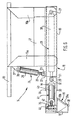
- the structure of the scraper device 14 is shown in FIGS. 5 and 6.
- This device comprises a rigid frame, for example of steel and mechanically welded, or of assembled aluminum elements, which is fixed to the rear of the frame of the table 13 of the paver 8, and which consists of two vertical uprights 15 a and 15 b , directly linked to the table 13 and connected to each other by a lower cross member 17.
- the amount 15 a is the external amount, that is to say closest to the lateral edge of the finisher 8 which is turned towards the side of a covering strip 1 previously laid (FIG. 1) and along which the finisher 8 is moved to lay an adjacent strip 2 which will be connected to the web 1 already raised by a seal, while the other leg is an inner post 15b closest to the median longitudinal plane and the finisher 8.
- a transverse extendable arm 18 of telescopic structure is pivotally mounted on the lower part of the chassis.
- This telescopic arm 18 consists of two sections of metal tubes of square section, forming two sliding boxes substantially coaxially one inside the other, and one of which is an external box 19, of larger cross section, in which the other box 20, or internal box, of smaller cross section, is slidably mounted by a part of its length.
- the external box 19 is pivotally mounted, about a horizontal axis 21 and parallel to the direction of movement of the paver 8, on the lower end of the upright 15 b , below the cross-member lower 17.
- the external box 19 is also pivotally mounted by a clip 22 and about an axis 23 parallel to the axis 21, on the lower end of the rod 25 of a double-acting hydraulic cylinder 24, arranged substantially along and outside the external upright 15 a .
- This jack 24 is itself pivotally mounted, by the upper end of its cylinder 26, on a fastener 27 fixed to the upright 15 a , and around an axis 28 parallel to the axes 21 and 23.
- a second double-acting hydraulic cylinder 29 In the telescopic arm 18 is axially housed a second double-acting hydraulic cylinder 29, the closed end of the cylinder 30 is retained by the axis 21 in the bottom of the outer box 19, while the rod 31 of this second cylinder s 'extends inside the internal box 20 and is retained by its end and using a fastening pin 32 in the portion closest to the external box 19 of a part of this internal box 20 which is always outside the external box 19, even when the jack 29 is retracted.
- This cylinder 29 thus constitutes a cylinder control of extensions and retractions of the telescopic arm 18 in transverse direction relative to the direction of movement of the finisher 8, since the outputs and re-entries of the rod 31 with respect to the cylinder 30 correspond respectively to the exits and re-entries of the internal box 20 vis-à-vis the external box 19.
- the part of the internal box 20 which is still cantilevered outside the external box 19 carries a fixing cap 33, of which the two upper and lower branches project forward, that is to say towards the table 13 of the finisher 8, and has an axial lumen 34 opening into the front and rear faces of the box 20, and which extends up to the proximity of the external end 35 of this part of the internal box 20.
- a vertical pivot axis 36 In this external end 35 of the box 20 is journalled a vertical pivot axis 36, projecting from the upper face of the central part of a blade doctor blade 37 elongated and straight.
- This scraper blade 37 intended to scrape against the upper face of the first coating strip laid 1 to bring the hot material of the covering 3 onto the second coating strip laid 2, can be made of a rubber resistant to the temperature of the material hot to scrape, that is to say at a temperature of the order of 110 to 120 ° C, or even wood, or even steel.
- This scraper blade 37 has a planar lower face 38, substantially horizontal, intended to come to scrape against the upper face of the first strip laid 1, and a face 39 for repelling the material, facing towards the interior, that is to say towards the chassis and towards the telescopic arm 18, and this pushing face 39 itself has a small lower part 39 a , perpendicular to the lower face 38, and a large upper part 39 b , inclined from bottom to top and from the outside towards the inside, in order to guide the covering material 3 well, when it is scraped over the top of the first strip laid 1 and pushed back to the top of the second band 2.
- the scraper blade 37 also carries projecting on its upper face, and substantially in the middle of its rear half, that is to say of its half located on the side opposite the table 13 of the finisher 8 relative to the axis.
- This cylinder 41 constitutes a cylinder for controlling the inclination of the scraper blade 37 relative to the direction of movement of the device with the finisher 8, since the outputs and re-entries of the rod 42 relative to the cylinder 43 of this cylinder control the pivoting of the blade 37 around its pivot axis 36 respectively clockwise and counterclockwise, if we consider the device in plan, as in Figure 6, that is to say respectively reconciliations and removals of the half before the blade 37 opposite the table 13 of the finisher 8.
- the arrangement of the articulations of the ends of the tilt cylinder 41 on either side of the axis of the internal box 20 of the telescopic arm 18 and the light 34 of this box 20 make it possible to use and advantageously house a cylinder of inclination 41 with a stroke long enough to give all the desirable inclinations to the scraper blade 37, without having to excessively increase the size and the weight of the entire part of the device overhanging relative to the external box 19 of the telescopic arm 18.
- the cylinder 41 for tilting or orienting the scraper blade 37, the cylinder 29 for retracting the telescopic arm 18, and therefore for transversely moving the scraper blade 37, and the cylinder 24 for vertically moving the blade 37 with the telescopic arm 18 are each supplied with hydraulic fluid by one respectively of three solenoid valves (not shown) which are fixed on the lower cross member 17 of the chassis, and whose hydraulic power stages are connected to the hydraulic circuit of the finisher 8 by quick-coupling and self-sealing couplings, while the electrical control stage of each solenoid valve is connected, by connectors with quick connection and disconnection, to the control unit 11 installed on the engine chassis 10 of the finisher 8.
- the scraper blade 37 can be mounted in a suitable working position, projecting from the left or right side of the table 13 of the finisher 8 relative to the direction of movement of the latter, the means of connection of this blade 37 to the finisher 8 and simultaneously of actuation of this blade 37 relative to this finisher 8, which constitute the three jacks and the telescopic arm 18 are means which are quickly and removably mounted on the chassis of the uprights 15 a and 15 b and of the cross member 17.
- transverse 18-29, vertical 24 and tilt 41 alternating actuation means are controlled according to a sequential operating cycle by the electronic sequencer of the programmable controller integrated in the central control unit 11, and an operating cycle. is broken down into six steps shown in Figures 7 a to 7 f and described with reference to these figures.
- FIG. 7 a represents the initial position of the cycle: the scraper blade 37 is brought back practically against the lateral edge of the table 13 of the finisher 8 and raised in maximum position well above the level of the upper face of the first strip laid 1, by the retraction of the jacks 29 and 24 and of the telescopic arm 18. Then, as shown in FIG. 7b , the extension of the jack 29 and of the telescopic arm 18, while the jack 24 remains retracted, controls the spacing lateral of the blade 37, which is inclined by its front half towards the table 13 by virtue of the extension of the jack 41.
- this jack controls the pivoting of the blade 37, the front half of which is moved away from the finisher, as shown in Figure 7c , and when the telescopic arm 18 reaches its extended position maximum, as shown in FIG. 7 d , the extension of the jack 24 controls the descent of the blade 37 against the upper face of the first strip laid 1, behind the covering 3, and the blade 37 is returned to the inclined position towards the back and inward by the tilt cylinder.
- the retraction of the telescopic arm 18 while the blade 37 is lowered causes the blade 37 to push back the covering material 3 which has just been laid by the finisher 8 at the same time as the second strip 2, and the inclination of the blade 37 on the direction of travel of the paver 8 is favorable for a good transfer of this covering material 3 from above the first strip 1 to above the second strip 2, as shown in FIG. 7 e .
- the blade 37 is brought back parallel to the side of the table 13 by the tilt cylinder (as shown in FIG. 7 f ) in order to obtain a length of bead of material which is indeed longitudinal, parallel to the connection between the two strips laid, and a short distance from the lateral edge 4 of the first strip laid 1.
- sequencer controls a new cycle, so that the device produces a longitudinal and continuous bead, suitably arranged to produce with sufficient material a good quality connection joint, by compacting the bead.
- the displacements of the scraper blade 37 are at least partially slaved to the instantaneous lateral position of this edge 4 relative to the finisher 8.
- This position is detected by the detector 12, fixed on the lateral edge of the corresponding side of the engine chassis 10, therefore in front of the table 13 of the finisher 8, and which includes a telemetric ultrasonic probe, sensitive to the edge 4 of the first band posed 1, that is to say to the rung, to the step or to the threshold delimited between the level of the upper face of the band 1 and the level of the upper face of the underlying layer.
- This ultrasonic probe 12 of the scanning type, therefore measures the instantaneous lateral spacing which separates it from the edge 4 of the first strip laid, that is to say from the position of the joint to be formed, and transmits a function signal. of this instantaneous lateral spacing to the computer integrated in the control center 11, which also receives a signal which is a function of the instantaneous longitudinal speed of movement of the finisher 8.
- the computer prepares signals modifying the values as required strokes of the cylinder 29 and possibly of the tilt cylinder 41, as well as the instants of actuation of the vertical displacement cylinder 24, and therefore the lifting and lowering positions of the scraper blade 37, that is to say -display the start and end positions of the cycle as well as the amplitudes of the spreading and approximation movements of the blade 37.
- the distance is known lateral b separating the detector 12, on the lateral edge of the motor chassis 10, from the maximum retraction position of the scraper blade 37, under the effect of the telescopic arm 18.
- L v is the total stroke of the telescopic arm 18
- the finisher 8 advances at a variable speed V
- the detector 12 is at a fixed distance L y known by construction at the front of the scraper blade 37
- the travel time of the distance L y by the blade 37 is a function of the speed V.
- the control unit computer 11 stores the instantaneous speed V t and the instantaneous lateral spacing L (x, t) , and it calculates the effective stroke C (x, t) so that the formed bead is well at the distance a from the joint J for the measurement L (x, t) .
- all the other movements of the scraper blade 37 can be automatically adjusted to the instantaneous lateral spacing of the joint relative to the finisher, i.e. starting positions, lifting, lowering, returning and transverse movements on one side and the other.
- the ultrasonic probe can be mounted on the free end of the rod of a double-acting hydraulic cylinder, fixed transversely and horizontally to the motor chassis 10 of the finisher 8, and whose rod is driven of an alternative movement over a total stroke of 20 centimeters for example.
- the lateral deviation of the probe is measured relative to the finisher, which corresponds to the lateral deviation of the joint. This lateral deviation can be measured by a potentiometric indicator coupled to the rod of the reciprocating cylinder.
- these detection means comprise a mechanical feeler, produced in the form of a roller mounted on the lower edge and external of the scraper blade 37, substantially in its central part.
- This roller is resiliently biased downward, that is to say towards the upper surface of the first or second strip laid 1 or 2, depending on the transverse position of the scraper blade 37, by a return spring, and the caster is conventionally associated with an electrical level switch connected to the computer of the control unit 11.
- the caster is sensitive to the passage between the first laid strip 1, the material of which is relatively hard, and the second laid strip 2 and not yet compacted, the material of which is still relatively soft.
- the electrical contactor When the edge 4 passes between the two strips 1 and 2, the electrical contactor is actuated and transmits a signal to the computer of the control unit 11, which also takes into account the transverse spacing of the joint between the two strips 1 and 2 for control the movements of the scraper blade 37.
- control of the effective lateral stroke of the scraper blade 37 can be such that this stroke is equal to the sum of a fraction of constant value, whatever the transverse position of the joint, and of a fraction of variable value, subject to this instantaneous transverse position of the joint.
- the scraper device described above provides great security and reliability in the preparation of the bead, and therefore in the quality of execution of the connection joint, while allowing substantial savings. labor.
- Another advantage of the device according to the invention is that it does not hinder movement on the adjacent and previously laid covering strip, since its lateral offset relative to the finisher is minimum, the essential of the scraper device being in the template. of the paver behind the latter's table.
- the single extension-retraction cylinder 29 of the preceding example is replaced by two double-acting hydraulic cylinders 45 and 46, mounted in series end to end and in extension one of the other, and essentially housed axially inside the external box 19 ′ of the transverse arm 18 ′ extendable and at least partially telescopic.
- the jack 45 is retained on the side of the closed bottom of its cylinder 47 in the internal end part of the box 19 ′ of the arm 18 ′, with which it is pivotally mounted around the pivot axis 21 ′ horizontal and longitudinal (parallel to the direction of movement of the paver) on a rear console 51 of the chassis of the device.
- the end of the rod 48 of the cylinder 45, outside the cylinder 47, is integral with the closed bottom of the cylinder 49 of the second cylinder 46, the end of the rod 50 outside of the cylinder 49 is pivotally articulated around the attachment axis 32 ′ horizontal on the internal box 20 ′ of the arm 18 ′, this internal box 20 ′ supporting, as in the previous example, a scraper blade 37 ′ projecting under the arm 18 ′ and laterally cantilevered towards the outside of the outer end of the inner box 19 ′ carrying an attachment 52 for connection to the jack (not shown) for lifting and lowering the arm 18 ′ by pivoting about the pivot axis 21 ′.
- the jack 45 is a jack for approach and overall lateral positioning of the scraper blade 37 ′, for example over a stroke of 0.2 m, and which allows this blade 37 ′ to be correctly positioned relative to the edge 4 of the strip 1 (see FIG. 1), that is to say at the joint to be produced between the two adjacent covering strips laid 1 and 2, while the jack 46 drives the scraper blade 37 ′ on an alternative cyclic stroke, which may be constant during the operating cycle and 0.2 m for example, for the formation, by scraping of the covering 3, of the bead necessary to obtain a suitable joint between the two covering strips 1 and 2.
- the scraper blade 37 ′ is not connected to the internal box 20 ′ of the arm 18 ′ by a hydraulic orientation cylinder, but this blade 37 ′ can however take one of three particular positions of orientation or inclination relative to the direction of movement of the device with the finisher.
- the scraper blade 37 ′ is, as in the previous example, pivotally mounted on the outer end 35 ′ of the external box 20 ′, around a vertical pivot axis 36 ′, using the framework of the upper part of this blade 37 ′, this framework comprising a longitudinal core 53 and two wings 54, transverse , vertical, spaced from each other and projecting towards the arm 18 ′, and between which a U-shaped yoke 55, with two horizontal, transverse and vertically spaced apart branches, is fixed so removable by a bolt 56 passing through a central stud 57, the core 53 and the base of the U-shaped clevis 55.
- the two branches of the clevis 55 have a pair of coaxial holes housing the pivot axis 36 ′ which also passes through a socket carried by the end 35 ′ of the box 20 ′, which is engaged between the two branches of the yoke 55.
- the two branches of the yoke 55 have three pairs of holes 58, coaxial two by two, and spaced from each other on a central arc on the axis 36 ′, so that by pivoting the blade 37 ′ around the axis 36 ′, one of the pairs of holes 58 can be arranged opposite a second socket carried by the box 20 ′, so that the housing of a pin 59 in this socket and the two opposite holes allow the blade 37 ′ to be blocked in one of the three angular positions thus permitted.
- the scraper blade 37 ′ is oriented parallel to the direction of movement of the device, by housing the pin 59 in the "central" pair of tilting holes 58, but the blade 37 ′ can be locked in an inclined position of 30 °, clockwise or counterclockwise, if the pin 59 is housed in one of the other two pairs of coaxial holes 58.
- the chassis of the device comprises a transverse support 17 ′, which is fixed to the rear of the table 13 of the finisher 8 by two attachment members 15 ′ a and 15 ′ b , and the internal end of the support 17 ′ carries, projecting rearward, a console 60, on which the console 51 linked to the arm 18 ′ is pivotally mounted about a vertical axis 61.
- the arm 18 ′ is also connected to the support 17 ′ by a safety mechanism 62, which comprises a set of two flexible steel blades 63, of the same dimension and joined against one another, and which are anchored, substantially in their central part, on a rigid anchoring lug 64 secured to the support 17 ′ and protruding towards the rear of the latter.
- the two flexible blades 63 are retained on a rigid tab 65 integral with the external box 19 ′ of the transverse arm 18 ′, and projecting towards the front of this box, while laterally from the 'other side of the leg 64, these blades 63 are in contact with the feeler 66 of a position detector 67 which controls the operation of the jack (not shown) for lifting and lowering of the transverse arm 18 ′ by pivoting around the axis 21 ′.
- the blades 63 and the vertical pivot axis 61 allow a certain overall rotation of the transverse arm 18 ′ and of the elements which it carries, around the axis 61, so that, when the scraper blade 37 ′ in operation meets, when it is moved longitudinally with the finisher, an obstacle such as a mouth or a sewer grate which opposes the pursuit of its advance, the scraper blade 37 ′ and the transverse arm 18 ′ pivot in an overall backward movement around the vertical axis 61, bending the flexible blades 63 counterclockwise (looking at Figure 9).
- the flexible blades 63 After a certain rotation towards the rear of the arm 18 ′, the flexible blades 63 are deformed so that they depress the probe 66 of the detector 67 over a stroke sufficient to trigger the operation of the lifting jack, which then raises the arm 18 ′ around the axis 21 ′, which allows the scraper blade 37 ′ to be lifted and released from the obstacle.
- the flexible metal blades 63 then pivot the arm 18 ′ around the vertical axis 61 forwards, to the initial position of the arm 18 ′, which releases the insertion of the probe 66 into the detector 67, which then controls the lowering of the arm 18 ′ by the lifting and lowering cylinder, so that the operating cycle can resume.
- the flexible metal blades 63 used can be of the type, well known, used for example as a leaf spring in automobile suspensions.
- the device of FIG. 9, in the configuration of scraping or of preparing a bead for the formation of a joint between two adjacent strips of coating, can be put in configuration of smoothing and compaction of a free and inclined edge of a covering strip which has just been laid, by mounting, on the internal box 20 ′ of the transverse arm 18 ′, of a smoothing blade and compaction 68 in place of the scraper blade 37 ′, which can be very simply deposited by removing the pin 59 and the vertical pivot axis 36 ′, which connect said scraper blade 37 ′ to this box 20 ′.
- Such a smoothing and compacting blade 68 is schematically represented in FIGS. 10 to 12, and described below with reference to these figures.
- This blade 68 comprises a framework consisting of an elongated section 69 of a rigid metal section of cross section in L, one wing 69 a wider than the other 69 b , is horizontal while the other wing 69 b is vertical and projecting under the wing 69 a , which supports, on its upper face, combined means of connection to the box 20 ′ of the arm 18 ′ and of pivoting on the box 20 ′ by the vertical axis 36 ′, and of wedging in orientation with respect to the longitudinal direction of the edge of the strip, which is also the direction of movement of the device.
- the blade 68 also comprises a pad 70 for contact with the material to be smoothed and compacted, this pad 70 having a substantially rectangular and elongated sole, the two end portions 71 of which are rounded and raised upwards, as shown in FIGS. 10 and 12, to facilitate moving the pad 70.
- the pad 70 is further pivotally mounted along one of its longitudinal sides on the bottom of the vertical flange end 69 b of the frame, by a hinge 72 having a horizontal axis and longitudinal. This hinge 72 makes it possible to give the shoe 70 any transverse inclination on the horizontal plane in order to properly apply the sole of this shoe 70 against the inclined surface of the free edge such as the edge 4 ′ of the strip laid 2 in FIG. 13.
- the adjustment and the blocking of the shoe 70 in a desired position of inclination around the hinge 72 is ensured by means of a mechanism with two tie rods 73 with at least partially threaded rod, which are pivotally articulated, each by their lower end 74, and around the same longitudinal axis (parallel to the long sides of the shoe 70) on the lateral part of the shoe 70 on the side opposite to the hinge 72, and the threaded part of the rod of each tie 73 crosses one of two transverse slots 75 formed in the lateral part of the horizontal wing 69 has a framework, on the side opposite to the hinge 72, nuts and locknuts 76 being screwed onto this threaded rod, below and a u above the wing 69 a and pressed against the edges of the corresponding lumen 75 to ensure that the shoe 70 is held in the chosen position.
- the transverse position of the blade 68 and the pressure of application of its pad 70 against the edge inclined with a laid covering strip are adjusted using the jack 47 (FIG. 9), and the smoothing and compact work is ensured by moving the blade 68 and the device with the finisher 8.
- the transverse position of the blade 68 can also be controlled by probes, as described previously with reference to FIGS. 4 and 8, but the detection probe in front, in in this case, be positioned just behind the table 13, so that the position of the inclined edge 4 ′ can be effectively detected.
Landscapes
- Engineering & Computer Science (AREA)
- Architecture (AREA)
- Civil Engineering (AREA)
- Structural Engineering (AREA)
- Road Repair (AREA)
- Road Paving Machines (AREA)
- Road Signs Or Road Markings (AREA)
- Treatment Of Fiber Materials (AREA)
- Rolls And Other Rotary Bodies (AREA)
Claims (23)
- ein festes Chassis (15a, 15b, 17) ist dazu eingerichtet, längs hinter der Maschine verstellt zu werden,
- ein Kratzer (37) ist dazu eingerichtet, gegen einen freien Rand einer niedergelegten Decke zu schaben, um ihn zu glätten und zu verdichten, oder gegen das erste niedergelegte Band (1) zu schaben, um von ihm Beschichtungsmaterial zu entfernen und auf die zweite Decke (2) zu decken, derart, daß auf letzterer eine Längswulst (6) aus Beschichtungsmaterial ausgeformt wird, die letztlich als Längsverbindung verdichtet wird, und
- Verbindungsmittel (18-29, 24, 41), die den Kratzer (37) mit dem Chassis verbinden und wenigstens vertikale und transversale Verlagerungen des Kratzers (37) bezüglich des Chassis und seiner Verlagerungsrichtung gestatten, dadurch gekennzeichnet, daß sie Betätigungsmittel umfaßt, wobei die Verbindungsmittel und die Betätigungsmittel wenigstens ein alternierendes Querverlagerungsorgan (18-29) des Kratzers (37) bezüglich des Chassis umfassen und wenigstens ein alternierendes vertiakles Verlagerungsorgan (24) des Kratzers (37) bezüglich des Chassis umfassen.
- ein Gerüst (69, 53, 54, 55) mittels dessen die Platte (68) in abnehmbarer Weise mit den Verbindungs- und Betätigungsmitteln (18′, 45, 46) verbunden ist,
- eine Kontaktkufe (70) zu dem Rand (4′) einer niedergelegten Decke (2), wobei die Außenteile (71) der Kufe (70) in Verlagerungsrichtung des Chassis (17′) vorzugsweise hochgezogen sind,
- eine Übergangsstelle (72) mit einer ungefähr horizontalen Achse zur Verbindung und Anbringung der Kufe (70) unter dem Gerüst (69), damit die Kufe (70) dieselbe Neigung wie der Rand (4′) der niedergelegten Decke (2) annehmen kann, und
- Mittel (73, 74, 75, 76) zum Einstellen und Arretieren der Neigung der Kufe (70) bezüglich des Gerüsts (69).
Priority Applications (1)
| Application Number | Priority Date | Filing Date | Title |
|---|---|---|---|
| AT88401898T ATE65095T1 (de) | 1987-07-22 | 1988-07-21 | Vorrichtung zum glaetten, verdichten und/oder abkratzen, insbesondere fuer die raender von strassendeckenschichten. |
Applications Claiming Priority (2)
| Application Number | Priority Date | Filing Date | Title |
|---|---|---|---|
| FR8710400A FR2618467B1 (fr) | 1987-07-22 | 1987-07-22 | Dispositif de raclage, notamment pour la preparation d'un joint de revetement routier |
| FR8710400 | 1987-07-22 |
Publications (2)
| Publication Number | Publication Date |
|---|---|
| EP0300913A1 EP0300913A1 (de) | 1989-01-25 |
| EP0300913B1 true EP0300913B1 (de) | 1991-07-10 |
Family
ID=9353442
Family Applications (1)
| Application Number | Title | Priority Date | Filing Date |
|---|---|---|---|
| EP88401898A Expired - Lifetime EP0300913B1 (de) | 1987-07-22 | 1988-07-21 | Vorrichtung zum Glätten, Verdichten und/oder Abkratzen, insbesondere für die Ränder von Strassendeckenschichten |
Country Status (6)
| Country | Link |
|---|---|
| EP (1) | EP0300913B1 (de) |
| AT (1) | ATE65095T1 (de) |
| DE (1) | DE3863602D1 (de) |
| ES (1) | ES2024037B3 (de) |
| FR (1) | FR2618467B1 (de) |
| GR (1) | GR3002456T3 (de) |
Families Citing this family (2)
| Publication number | Priority date | Publication date | Assignee | Title |
|---|---|---|---|---|
| DE4400282A1 (de) * | 1994-01-07 | 1995-07-13 | Alfred Soeder | Kanten-Plattenverdichter |
| BE1018770A3 (nl) * | 2009-06-04 | 2011-08-02 | Hoogmartens Wegenbouw | Asfalteringsmachine met geintegreerde voegaanbrenger. |
Family Cites Families (3)
| Publication number | Priority date | Publication date | Assignee | Title |
|---|---|---|---|---|
| US3603223A (en) * | 1969-03-11 | 1971-09-07 | Frank Strausberg & Son Co | Apparatus and methods for forming a joint between adjacent paving mats |
| US3914064A (en) * | 1971-03-01 | 1975-10-21 | Raymond A Gurries | Mounting arrangement for sidewalk building equipment or the like |
| DE2941017A1 (de) * | 1979-10-10 | 1981-04-23 | Hoffmann, geb. Eisler, Elisabeth, 6670 St Ingbert | Einem strassenfertiger nachgeordnete vorrichtung zum verdichten des seitlichen randes einer gefertigten strassendecke |
-
1987
- 1987-07-22 FR FR8710400A patent/FR2618467B1/fr not_active Expired
-
1988
- 1988-07-21 ES ES88401898T patent/ES2024037B3/es not_active Expired - Lifetime
- 1988-07-21 DE DE8888401898T patent/DE3863602D1/de not_active Expired - Fee Related
- 1988-07-21 AT AT88401898T patent/ATE65095T1/de not_active IP Right Cessation
- 1988-07-21 EP EP88401898A patent/EP0300913B1/de not_active Expired - Lifetime
-
1991
- 1991-08-08 GR GR91401155T patent/GR3002456T3/el unknown
Also Published As
| Publication number | Publication date |
|---|---|
| DE3863602D1 (de) | 1991-08-14 |
| ATE65095T1 (de) | 1991-07-15 |
| EP0300913A1 (de) | 1989-01-25 |
| FR2618467B1 (fr) | 1989-12-15 |
| ES2024037B3 (es) | 1992-02-16 |
| FR2618467A1 (fr) | 1989-01-27 |
| GR3002456T3 (en) | 1992-12-30 |
Similar Documents
| Publication | Publication Date | Title |
|---|---|---|
| EP0230072B1 (de) | Vorrichtung und Verfahren zum Bürsten | |
| EP0470877B1 (de) | Vorrichtung zum Verteilen einer flüssigen Substanz und Maschine zum gleichzeitigen Aufbringen der Substanz und eines Strassendeckenmaterials | |
| EP0484220A1 (de) | Strassenfertiger | |
| CA2224443A1 (fr) | Lame pivotante pour souffleuse a neige | |
| FR2662452A1 (fr) | Machine de coulee en continu de beton pour la realisation des ornieres, rigoles ou voies etroites en beton. | |
| FR2635797A1 (fr) | Machine autopropulsee pour betonner les fosses | |
| CA1260304A (fr) | Outil de moulage tracte pour la realisation de dalles de beton sur le sol | |
| EP1197606B1 (de) | Vorrichtung zum Absaugen von Restwasser auf Pflaster- oder Betonflächen | |
| EP3617409B1 (de) | Vorrichtung und verfahren zum mechanischen füllen von gräben | |
| EP0300913A1 (de) | Vorrichtung zum Glätten, Verdichten und/oder Abkratzen, insbesondere für die Ränder von Strassendeckenschichten | |
| EP0509877B1 (de) | Vorrichtung zum Erstellen eines Strassenbelags durch sukzessive Streuung von einer Klebe- und einer heissen, bituminösen Schicht auf der zudeckenden Strassenoberfläche | |
| US10309069B1 (en) | Street sweeper | |
| FR2652098A1 (fr) | Table de compactage et de finissage d'un revetement routier a largeur de travail reglable comportant des moyens de repandage de liant liquide. | |
| WO1991000392A1 (fr) | Machine finisseuse niveleuse multifonction pour la construction de remblais routiers et autres | |
| FR2697037A1 (fr) | Dispositif et procédé pour déposer un matériau de reconstitution d'une chaussée dans une tranchée longitudinale. | |
| JPH05287705A (ja) | 自走式敷き均し機 | |
| FR2644806A1 (fr) | Regleuse-surfaceuse pour chaussees | |
| FR2758228A1 (fr) | Machine agricole, en particulier de preparation du sol et de dechaumage comportant des moyens d'entrainement en pivotement des trains porteurs d'outils | |
| FR3019566B1 (fr) | Machine pour le betonnage en continu de fosses munie d'un treuil | |
| FR2761703A1 (fr) | Appareil pour deposer sur une tranchee ou sur la chaussee une bande de materiau de reconstitution de chaussee | |
| EP3366840A1 (de) | Gezogene maschine, die insbesondere für die reparatur und instandhaltung von böden bestimmt ist, vor allem für strassen | |
| FR2714920A1 (fr) | Machine autochargeuse pour le remblayage de tranchées. | |
| FR2762338A1 (fr) | Dispositif pour chanfreiner au moins une bordure d'une bande de revetement fraichement posee sur une chaussee | |
| FR2779453A1 (fr) | Perfectionnement d'une regleuse-surfaceuse a lame deportee pour chaussee et trottoir | |
| FR2659676A1 (fr) | Machine pour le nettoyage des plages de sable. |
Legal Events
| Date | Code | Title | Description |
|---|---|---|---|
| PUAI | Public reference made under article 153(3) epc to a published international application that has entered the european phase |
Free format text: ORIGINAL CODE: 0009012 |
|
| AK | Designated contracting states |
Kind code of ref document: A1 Designated state(s): AT BE CH DE ES FR GB GR IT LI LU NL SE |
|
| 17P | Request for examination filed |
Effective date: 19890109 |
|
| 17Q | First examination report despatched |
Effective date: 19900423 |
|
| GRAA | (expected) grant |
Free format text: ORIGINAL CODE: 0009210 |
|
| AK | Designated contracting states |
Kind code of ref document: B1 Designated state(s): AT BE CH DE ES FR GB GR IT LI LU NL SE |
|
| REF | Corresponds to: |
Ref document number: 65095 Country of ref document: AT Date of ref document: 19910715 Kind code of ref document: T |
|
| ITF | It: translation for a ep patent filed | ||
| REF | Corresponds to: |
Ref document number: 3863602 Country of ref document: DE Date of ref document: 19910814 |
|
| GBT | Gb: translation of ep patent filed (gb section 77(6)(a)/1977) | ||
| REG | Reference to a national code |
Ref country code: ES Ref legal event code: FG2A Ref document number: 2024037 Country of ref document: ES Kind code of ref document: B3 |
|
| PLBE | No opposition filed within time limit |
Free format text: ORIGINAL CODE: 0009261 |
|
| STAA | Information on the status of an ep patent application or granted ep patent |
Free format text: STATUS: NO OPPOSITION FILED WITHIN TIME LIMIT |
|
| 26N | No opposition filed | ||
| REG | Reference to a national code |
Ref country code: GR Ref legal event code: FG4A Free format text: 3002456 |
|
| REG | Reference to a national code |
Ref country code: GB Ref legal event code: 746 Effective date: 19940614 |
|
| EPTA | Lu: last paid annual fee | ||
| EAL | Se: european patent in force in sweden |
Ref document number: 88401898.7 |
|
| PGFP | Annual fee paid to national office [announced via postgrant information from national office to epo] |
Ref country code: FR Payment date: 19970529 Year of fee payment: 10 |
|
| PGFP | Annual fee paid to national office [announced via postgrant information from national office to epo] |
Ref country code: GR Payment date: 19970611 Year of fee payment: 10 Ref country code: AT Payment date: 19970611 Year of fee payment: 10 |
|
| PGFP | Annual fee paid to national office [announced via postgrant information from national office to epo] |
Ref country code: ES Payment date: 19970708 Year of fee payment: 10 |
|
| PGFP | Annual fee paid to national office [announced via postgrant information from national office to epo] |
Ref country code: BE Payment date: 19970711 Year of fee payment: 10 |
|
| PGFP | Annual fee paid to national office [announced via postgrant information from national office to epo] |
Ref country code: GB Payment date: 19970714 Year of fee payment: 10 |
|
| PGFP | Annual fee paid to national office [announced via postgrant information from national office to epo] |
Ref country code: SE Payment date: 19970717 Year of fee payment: 10 |
|
| PGFP | Annual fee paid to national office [announced via postgrant information from national office to epo] |
Ref country code: DE Payment date: 19970723 Year of fee payment: 10 |
|
| PGFP | Annual fee paid to national office [announced via postgrant information from national office to epo] |
Ref country code: CH Payment date: 19970728 Year of fee payment: 10 |
|
| PGFP | Annual fee paid to national office [announced via postgrant information from national office to epo] |
Ref country code: NL Payment date: 19970731 Year of fee payment: 10 |
|
| PGFP | Annual fee paid to national office [announced via postgrant information from national office to epo] |
Ref country code: LU Payment date: 19970812 Year of fee payment: 10 |
|
| PG25 | Lapsed in a contracting state [announced via postgrant information from national office to epo] |
Ref country code: LU Free format text: LAPSE BECAUSE OF NON-PAYMENT OF DUE FEES Effective date: 19980721 Ref country code: GB Free format text: LAPSE BECAUSE OF NON-PAYMENT OF DUE FEES Effective date: 19980721 Ref country code: AT Free format text: LAPSE BECAUSE OF NON-PAYMENT OF DUE FEES Effective date: 19980721 |
|
| PG25 | Lapsed in a contracting state [announced via postgrant information from national office to epo] |
Ref country code: SE Free format text: LAPSE BECAUSE OF NON-PAYMENT OF DUE FEES Effective date: 19980722 Ref country code: ES Free format text: LAPSE BECAUSE OF THE APPLICANT RENOUNCES Effective date: 19980722 |
|
| PG25 | Lapsed in a contracting state [announced via postgrant information from national office to epo] |
Ref country code: LI Free format text: LAPSE BECAUSE OF NON-PAYMENT OF DUE FEES Effective date: 19980731 Ref country code: GR Free format text: LAPSE BECAUSE OF NON-PAYMENT OF DUE FEES Effective date: 19980731 Ref country code: CH Free format text: LAPSE BECAUSE OF NON-PAYMENT OF DUE FEES Effective date: 19980731 Ref country code: BE Free format text: LAPSE BECAUSE OF NON-PAYMENT OF DUE FEES Effective date: 19980731 |
|
| BERE | Be: lapsed |
Owner name: S.A. COLAS Effective date: 19980731 |
|
| PG25 | Lapsed in a contracting state [announced via postgrant information from national office to epo] |
Ref country code: NL Free format text: LAPSE BECAUSE OF NON-PAYMENT OF DUE FEES Effective date: 19990201 |
|
| GBPC | Gb: european patent ceased through non-payment of renewal fee |
Effective date: 19980721 |
|
| REG | Reference to a national code |
Ref country code: CH Ref legal event code: PL |
|
| EUG | Se: european patent has lapsed |
Ref document number: 88401898.7 |
|
| PG25 | Lapsed in a contracting state [announced via postgrant information from national office to epo] |
Ref country code: FR Free format text: LAPSE BECAUSE OF NON-PAYMENT OF DUE FEES Effective date: 19990331 |
|
| NLV4 | Nl: lapsed or anulled due to non-payment of the annual fee |
Effective date: 19990201 |
|
| PG25 | Lapsed in a contracting state [announced via postgrant information from national office to epo] |
Ref country code: DE Free format text: LAPSE BECAUSE OF NON-PAYMENT OF DUE FEES Effective date: 19990501 |
|
| REG | Reference to a national code |
Ref country code: FR Ref legal event code: ST |
|
| REG | Reference to a national code |
Ref country code: ES Ref legal event code: FD2A Effective date: 20001102 |
|
| PG25 | Lapsed in a contracting state [announced via postgrant information from national office to epo] |
Ref country code: IT Free format text: LAPSE BECAUSE OF NON-PAYMENT OF DUE FEES;WARNING: LAPSES OF ITALIAN PATENTS WITH EFFECTIVE DATE BEFORE 2007 MAY HAVE OCCURRED AT ANY TIME BEFORE 2007. THE CORRECT EFFECTIVE DATE MAY BE DIFFERENT FROM THE ONE RECORDED. Effective date: 20050721 |