EP0301251A2 - Radiation chopping arrangement - Google Patents
Radiation chopping arrangement Download PDFInfo
- Publication number
- EP0301251A2 EP0301251A2 EP88110262A EP88110262A EP0301251A2 EP 0301251 A2 EP0301251 A2 EP 0301251A2 EP 88110262 A EP88110262 A EP 88110262A EP 88110262 A EP88110262 A EP 88110262A EP 0301251 A2 EP0301251 A2 EP 0301251A2
- Authority
- EP
- European Patent Office
- Prior art keywords
- chopper
- radiation
- chopper device
- radiation chopper
- bearing
- Prior art date
- Legal status (The legal status is an assumption and is not a legal conclusion. Google has not performed a legal analysis and makes no representation as to the accuracy of the status listed.)
- Withdrawn
Links
Images


Classifications
-
- G—PHYSICS
- G01—MEASURING; TESTING
- G01J—MEASUREMENT OF INTENSITY, VELOCITY, SPECTRAL CONTENT, POLARISATION, PHASE OR PULSE CHARACTERISTICS OF INFRARED, VISIBLE OR ULTRAVIOLET LIGHT; COLORIMETRY; RADIATION PYROMETRY
- G01J3/00—Spectrometry; Spectrophotometry; Monochromators; Measuring colours
- G01J3/02—Details
- G01J3/08—Beam switching arrangements
-
- G—PHYSICS
- G02—OPTICS
- G02B—OPTICAL ELEMENTS, SYSTEMS OR APPARATUS
- G02B26/00—Optical devices or arrangements for the control of light using movable or deformable optical elements
- G02B26/02—Optical devices or arrangements for the control of light using movable or deformable optical elements for controlling the intensity of light
- G02B26/04—Optical devices or arrangements for the control of light using movable or deformable optical elements for controlling the intensity of light by periodically varying the intensity of light, e.g. using choppers
Definitions
- the invention relates to a radiation chopper device with a chopper disc.
- Optical chopper disks are preferably used in analyzers that determine the absorption capacity of a solid, liquid or gaseous substance. Your task is to briefly interrupt one or more light rays that fall directly or indirectly on a light-sensitive sensor. The interruption and re-release of a light beam is also called light modulation. In many cases, this light modulation is used to separate the actual measurement signal from interference signals. In the case of multichannel analysis devices, a chopper disc can also be used to interrupt or release the light in a first channel at a first time and to release the light in a second channel at a second time.
- a light interruption device for photometric measuring devices which has a motor which rotates an aperture which interrupts the light radiation, the motor having a cylindrical rotor and the motor housing being perforated in the axial direction in order to transmit the light radiation in this direction through the housing and let the rotor pass through (DE-OS 24 02 865).
- the rotor shaft is connected to the rotor by a memory-like element and the diaphragm is attached to the rotor shaft outside the motor housing.
- the disadvantage of this known interruption device is that a synchronous motor is required as the drive motor.
- the chopper disc In another light chopper device, the chopper disc is directly connected to a shaft of a drive motor (US Pat. No. 4,509,819, FIG. 26). The task of the chopper disk, however, is to reflect the incident light.
- a chopper device for a device for measuring the optical absorption behavior is also known, which is formed by a Ferrari motor which comprises a chopper disc and two electromagnet systems (DE-OS 26 08 669).
- a disk is surrounded by a disk-shaped vacuum chamber.
- several openings are arranged uniformly distributed on the circumference, which in connection with the parts of the disk located between them cause the actual chopping of light.
- a disadvantage of this internally mounted chopper disk is that it can easily tilt and is subject to a temperature drift. So-called chopper jumping occurs during operation, i. H. there are two metastable states of the chopper wheel / housing combination. These conditions result from the necessary bearing clearances so that the entire system only works with floating friction when the temperature changes. The bearing clearance is in turn due to the use of different materials with different coefficients of thermal expansion.
- the manufacturing tolerances for the known geometry enable small bearing clearances.
- the drive axis of a rotating filter disk is housed in a housing with ball bearings and in this way ensures that the filter disk is operated at a few 1000 rpm (DD-PS 216 323, Page 2, last paragraph).
- This chopper disc is also subject to a temperature drift.
- the object of the invention is therefore to improve the running properties of a chopper disc.
- the chopper disc is coupled at one end of its axis to a bearing device which has at least two support points with which it rests on a part in which the second end of the axis is mounted.
- the advantage achieved with the invention is in particular that the chopper disc no longer tilt and the so-called chopper noise is minimized.
- the non-tilting is essentially due to the fact that the chopper disc has a three-point bearing. This three-point bearing prevents shifts in the axis in the horizontal and vertical directions. The three-point bearing also reduces the bearing play, so that the temperature drift is significantly reduced. This is associated with a decrease in the chopper noise.
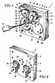
- This chopper device 1 shows a perspective view of the front of a chopper device 1 according to the invention.
- This chopper device 1 consists of two parts 2, 3 which can be connected to one another, the front part 3 having a smaller depth than the rear part 2.
- a lateral groove 4 which has a through-hole 5 in its lower end.
- a corresponding groove 6 on the opposite side of the rear part 2 can also be seen.
- the grooves 4, 6 are used to attach the chopper 1 in a housing, not shown.
- a bolt not shown, is inserted into the through hole 5.
- the front part 3 of the chopper device carries a Ferrari motor 7 which has two windings 8, 9 which surround legs of the magnets 10, 11.
- a Ferrari motor 7 which has two windings 8, 9 which surround legs of the magnets 10, 11.
- Electrical leads 18 - 21 are connected to these solderings 14 - 17, three leads 19, 20, 21 of which are led to a common coupler 22.
- the front and rear parts 2, 3 are connected to one another by means of Allen screws 23-26.
- holes 69, 75 are provided for receiving dowel pins.
- the front part 3 has a through-hole 27, behind which a chopper disk 28 can be seen.
- the through hole 27 is surrounded by an annular cut-out 29 in which three screws 30, 31, 32 are inserted.
- a through-hole corresponding to the through-hole 27 below the winding 9 is covered by a round plastic disk 33 which is fastened by means of screws 34, 35, 36 and nuts 37, 38, 39.
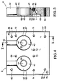
- FIG. 2 shows the rear of the rear part 2 of the chopper device 1.
- This rear side has two cylindrical bores 40, 41, each of which has an opening 42, 43, the depth of which corresponds to the depth of the bores 40, 41.
- In the respective bottom 44, 45 of the bores 40, 41 there is a through-hole 46, 47, behind which the chopper disk 28 passes.
- FIG. 3 shows the rear view of the device shown in FIG. 2 or the top view of the rear part 2 when the front part 3 is removed in the illustration in FIG. 1.
- the deepest cut-outs are located in the central area and are provided with the reference numbers 48, 49, 50.
- the outer ends 51, 52, 53 of these cutouts 48, 49, 50 are approximately a quarter less deep.
- the cutouts 54, 55, which adjoin the projection 56, are considerably less deep.
- These cutouts 54, 55 serve to receive parts of the Ferrari motor 7, not shown, which have approximately the shape of the yokes of the magnets 10, 11, which are shown in FIG. 1.
- the projection 56 is only slightly higher than the central area of the cutouts 54, 55 and thus corresponds in terms of its depth to the edge area 57, 58 of the cutouts 54, 55.
- 59, 60, 61, 62 holes are indicated through which connecting screws can be inserted .
- All inner recesses are surrounded by an annular groove 63, which has only a small depth.
- With 122, 123 dowel pins are firmly pressed.
- FIG. 4 the device shown in Fig. 2 is shown again in plan view, but rotated by 180 °.
- the through-holes 46, 47 are surrounded by an annular edge 64, 65 which is slightly lower than the respective base 44, 45.
- the upper edges of the bores 40, 41 are chamfered, which is represented by the circular rings 66, 67.
- part 2 several bores 68-75, 59-62 are provided, of which only the bores 59-62 go completely through part 2.
- the two lateral edges of part 2 have bevels 76, 77.
- FIG. 5 shows a section VV through part 2 in FIG. 4.
- FIG. 6 shows a top view of the part 2 shown in FIG. 3, namely rotated by 180 °.
- Two sloping surfaces 81, 82 can be seen, which lie between the cutouts 48 and 52 or 48 and 50.
- the groove 53 serves to receive part of a bearing block.
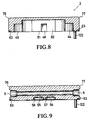
- a section VII-VII through part 2 (FIG. 6) is shown in FIG. 7.
- FIG. 8 shows a section VIII-VIII through part 2
- FIG. 9 shows a section IX-IX through this part 2.
- a pressed dowel pin is designated 122 here.
- Fig. 10 the back of the front part 3 (Fig. 1) is shown.
- the chopper disk 85 is rotatably mounted just above a recess 86 by means of a shaft 87.
- the recess 27 recognizable in FIG. 1 can also be seen in FIG. 10.
- the plastic disk 33 can be seen behind a further recess 88.
- the counter bearing for the shaft 87 is located in a device 89 which has three legs 90, 91, 92. Each of these legs 90-92 is divided into several sections.
- the legs 90, 92 are screwed to the part 3 with ends 93, 94 angled forward and by means of screws 95, 96.
- the adjoining legs 95a, 96a lie at the same level with these ends 93, 94 and then merge into the ascending legs 97, 98. These ascending legs in turn open into the legs 99, 100, which are connected to one another by a connecting piece 101.
- the third arm 91 is constructed similarly to the other two arms 90, 92; however, its individual legs 102, 103, 104 are not angled to one another in the horizontal. In contrast, the legs 95a and 99 or 96a and 100 form an angle of approximately 45 degrees in the horizontal.
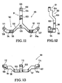
- FIG. 11 shows the device 89 again in a top view.
- 105 is a bore through which the shaft 87 (FIG. 10) is guided.
- Lugs 106, 107, 108 with bores 109, 110, 111 are provided for the arrangement of screws.
- FIG. 12 shows a side view of that shown in FIG. 11 Device 1. Only the legs 90 and 91 can be seen in this illustration.
- FIG. 13 shows a side view of the device 89, this device being tilted by 90 ° in comparison to the illustration in FIG. 11.
- the contact surfaces of the device 89 for the connection to the part 3 are consequently directed upwards and provided with the reference numbers 112, 113, 114.
- FIG. 14 shows a top view of part 3, with the ferrari motor removed. Where the legs of the ferrari motor surrounded by electrical windings are pushed through part 3, bores 115, 116 are provided. The legs of the Ferrari motor, which are not surrounded by windings, are pushed through holes 117, 118.
- the assembly of the parts 2, 3 to the device 1 shown in FIG. 1 takes place in such a way that the device 89 of the part 3 is introduced into the corresponding recesses 48-55 of the part 2. Then both parts are screwed together.
- the chopper 85 driven by the Ferrari motor 7 can now rotate in the space formed by the depression 78 in part 2 and by the depression 86 in part 3.
- cuvettes are inserted in the figures, which are filled, for example, with a gas to be analyzed.
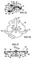
- FIG. 15 A variant of the invention is shown in FIG. 15, in which the chopper disk 85 forms a unit with the device 89. This makes it possible to remove this unit from parts 2, 3. In this solution, the device 89 no longer needs to be screwed to a part 2, 3 at the ends of its arms 90, 91, 92.
- This advantage is achieved by a component which has the shape of a vertical projection of the device 89 and of which the ends 130, 131, 132 can be seen in FIG. 15.
- the chopper disk 85 is thus arranged between the mentioned component and the device 89, the shaft 87 about which it rotates being mounted in both the component and the device 89.
- Fig. 16 shows a bottom view of the arrangement of Fig. 15, i. H. the component, which was arranged with its ends 130, 131, 132 below the device 89 in FIG. 15, now lies above this device 89.
- 137 denotes a screw which is surrounded by a nut 136. Both screw 137 and nut 136 serve to secure the bearing to the component in which shaft 87 rotates.
- threaded bores 133, 134, 135 are provided, into which screws can be inserted, with which this component can be attached to part 3.
- FIG. 17 shows a side view of the unit consisting of chopper disk 85, component and device 89. It can clearly be seen here that the chopper disk 85 is arranged just below the component.
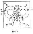
- FIG. 18 shows a variant of the device according to FIG. 14, which is suitable for receiving the unit consisting of chopper disk 85, component and device 89.
- This device has four bores, of which a central bore 141 serves to receive or include the screw 137 and the nut 136.
- This middle hole 141 is surrounded by three further bores 142, 143, 144, through which screws, not shown, can be inserted and screwed into the threaded bores 133 -135 of the component. 140 is a recess.
Landscapes
- Physics & Mathematics (AREA)
- Spectroscopy & Molecular Physics (AREA)
- General Physics & Mathematics (AREA)
- Optics & Photonics (AREA)
- Motor Or Generator Frames (AREA)
- Photometry And Measurement Of Optical Pulse Characteristics (AREA)
- Investigating Or Analysing Materials By Optical Means (AREA)
- Connection Of Motors, Electrical Generators, Mechanical Devices, And The Like (AREA)
Abstract
Description
Die Erfindung betrifft eine Strahlungs-Zerhackereinrichtung mit einer Zerhackerscheibe.The invention relates to a radiation chopper device with a chopper disc.
Optische Zerhackerscheiben werden vorzugsweise bei Analysegeräten verwendet, mit denen das Absorptionsvermögen eines festen, flüssigen oder gasförmigen Stoffs festgestellt wird. Ihre Aufgabe besteht darin, einen oder mehrere Lichtstrahlen, die unmittelbar oder mittelbar auf einen lichtempfindlichen Sensor fallen, kurzzeitig zu unterbrechen. Die Unterbrechung und erneute Freigabe eine Lichtstrahls wird auch Lichtmodulation genannt. Diese Lichtmodulation geschieht in vielen Fällen zum Trennen des eigentlichen Meßsignals von Störsignalen. Bei mehrkanaligen Analysegeräten kann eine Zerhackerscheibe auch dazu verwendet werden, zu einem ersten Zeitpunkt das Licht in einem ersten Kanal und zu einem zweiten Zeitpunkt das Licht in einem zweiten Kanal zu unterbrechen oder freizugeben.Optical chopper disks are preferably used in analyzers that determine the absorption capacity of a solid, liquid or gaseous substance. Your task is to briefly interrupt one or more light rays that fall directly or indirectly on a light-sensitive sensor. The interruption and re-release of a light beam is also called light modulation. In many cases, this light modulation is used to separate the actual measurement signal from interference signals. In the case of multichannel analysis devices, a chopper disc can also be used to interrupt or release the light in a first channel at a first time and to release the light in a second channel at a second time.
Es ist bereits eine Lichtunterbrechungsvorrichtung für photometrische Meßgeräte bekannt, die einen Motor aufweist, der eine die Lichtstrahlung unterbrechende Blende in Rotation versetzt, wobei der Motor einen zylindrischen Rotor besitzt und das Motorgehäuse in axialer Richtung durchbrochen ist, um die Lichtstrahlung in dieser Richtung durch das Gehäuse und den Rotor hindurchtreten zu lassen (DE-OS 24 02 865). Hierbei ist die Rotorwelle mit dem Rotor durch ein speicherartiges Element verbunden und auf der Rotorwelle außerhalb des Motorgehäuses die Blende befestigt. Nachteilig ist bei dieser bekannten Unterbrechungsvorrichtung, daß als Antriebsmotor ein Synchronmotor erforderlich ist.A light interruption device for photometric measuring devices is already known which has a motor which rotates an aperture which interrupts the light radiation, the motor having a cylindrical rotor and the motor housing being perforated in the axial direction in order to transmit the light radiation in this direction through the housing and let the rotor pass through (DE-OS 24 02 865). Here, the rotor shaft is connected to the rotor by a memory-like element and the diaphragm is attached to the rotor shaft outside the motor housing. The disadvantage of this known interruption device is that a synchronous motor is required as the drive motor.
Bei einer anderen Lichtzerhackereinrichtung ist die Zerhackerscheibe direkt mit einer Welle eines Antriebsmotors verbunden (US-PS 4 509 819, Fig. 26). Die Aufgabe der Zerhackerscheibe besteht hierbei jedoch darin, das auftreffende Licht zu reflektieren.In another light chopper device, the chopper disc is directly connected to a shaft of a drive motor (US Pat. No. 4,509,819, FIG. 26). The task of the chopper disk, however, is to reflect the incident light.
Es ist weiterhin eine Zerhackereinrichtung für eine Vorrichtung zur Messung des optischen Absorptionsverhaltens bekannt, die durch einen Ferrarismotor gebildet ist, der eine Zerhackerscheibe sowie zwei Elektromagnetsysteme umfaßt (DE-OS 26 08 669). Bei einer Ausbildungsform dieser bekannten Zerhackereinrichtung ist eine Scheibe von einer scheibenförmigen Vakuumkammer umgeben. In dieser Scheibe sind auf dem Umfang gleichförmig verteilt mehrere Öffnungen angeordnet, die in Verbindung mit den zwischen ihnen befindlichen Teilen der Scheibe die eigentliche Lichtzerhackung bewirken. Nachteilig ist indessen bei dieser innengelagerten Zerhackerscheibe, daß sie sich leicht verkanten kann und einer Temperaturdrift unterliegt. Während des Betriebs tritt ein sogenanntes Chopper-Springen auf, d. h. es liegen zwei metastabile Zustände der Kombination Chopperrad/Gehäuse vor. Diese Zustände ergeben sich aufgrund der notwendigen Lagerspiele, damit bei Temperaturänderungen das Gesamtsystem nur mit schwimmender Reibung arbeitet. Das Lagerspiel ist seinerseits bedingt durch die Verwendung unterschiedlicher Materialien mit unterschiedlichen Wärmeausdehnungskoeffizienten. Außerdem ermöglichen die Fertigungstoleranzen für die bekannte Geometrie kleine Lagerspiele.A chopper device for a device for measuring the optical absorption behavior is also known, which is formed by a Ferrari motor which comprises a chopper disc and two electromagnet systems (DE-OS 26 08 669). In one embodiment of this known chopper device, a disk is surrounded by a disk-shaped vacuum chamber. In this disk several openings are arranged uniformly distributed on the circumference, which in connection with the parts of the disk located between them cause the actual chopping of light. A disadvantage of this internally mounted chopper disk is that it can easily tilt and is subject to a temperature drift. So-called chopper jumping occurs during operation, i. H. there are two metastable states of the chopper wheel / housing combination. These conditions result from the necessary bearing clearances so that the entire system only works with floating friction when the temperature changes. The bearing clearance is in turn due to the use of different materials with different coefficients of thermal expansion. In addition, the manufacturing tolerances for the known geometry enable small bearing clearances.
Bei einem anderen bekannten elektromechanischen Licht-Chopper, der für vier verschiedene Wellenlängen verwendbar ist, ist die Antriebsachse einer rotierenden Filterscheibe in einem Gehäuse kugelgelagert untergebracht und gewährleistet auf diese Weise das Betreiben der Filterscheibe mit einigen 1000 U/min (DD-PS 216 323, Seite 2, letzter Absatz). Auch diese Zerhackerscheibe unterliegt einer Temperaturdrift.In another known electromechanical light chopper, which can be used for four different wavelengths, the drive axis of a rotating filter disk is housed in a housing with ball bearings and in this way ensures that the filter disk is operated at a few 1000 rpm (DD-PS 216 323,
Die Erfindung liegt deshalb die Aufgabe zugrunde, die Laufeigenschaften einer Zerhackerscheibe zu verbessern.The object of the invention is therefore to improve the running properties of a chopper disc.
Diese Aufgabe wird dadurch gelöst, daß die Zerhackerscheibe mit dem einen Ende ihrer Achse mit einer Lagervorrichtung gekoppelt ist, die wenigstens zwei Auflagestellen aufweist, mit denen sie auf einem Teil aufliegt, in dem das zweite Ende der Achse gelagert ist.This object is achieved in that the chopper disc is coupled at one end of its axis to a bearing device which has at least two support points with which it rests on a part in which the second end of the axis is mounted.
Der mit der Erfindung erzielte Vorteil besteht insbesondere darin, daß sich die Zerhackerscheibe nicht mehr verkanten und das sogenannte Zerhackerrauschen minimiert wird. Das Nichtverkanten beruht im wesentlichen darauf, daß die Zerhackerscheibe eine Dreipunktlagerung aufweist. Durch diese Dreipunktlagerung werden Verschiebungen der Achse in horizontaler und in vertikaler Richtung vermieden. Die Dreipunktlagerung verringert auch das Lagerspiel, so daß die Temperaturdrift erheblich reduziert wird. Damit verbunden ist eine Abnahme des Zerhacker-Rauschens.The advantage achieved with the invention is in particular that the chopper disc no longer tilt and the so-called chopper noise is minimized. The non-tilting is essentially due to the fact that the chopper disc has a three-point bearing. This three-point bearing prevents shifts in the axis in the horizontal and vertical directions. The three-point bearing also reduces the bearing play, so that the temperature drift is significantly reduced. This is associated with a decrease in the chopper noise.
Ausführungsbeispiele der Erfindung sind in der Zeichung dargestellt und werden im folgenden näher beschrieben. Es zeigen:
- Fig. 1 eine perspektivische Darstellung der Vorderseite einer erfindungsgemäßen Zerhackereinrichtung;
- Fig. 2 eine perspektivische Darstellung der Rückseite des hinteren Teils der erfindungsgemäßen zweiteiligen Zerhackereinrichtung;
- Fig. 3 eine perspektivische Darstellung der Rückseite des in der Fig. 2 dargestellten Teils der Zerhackereinrichtung;
- Fig. 4 eine direkte Draufsicht auf das in der Fig. 2 dargestellte Teil, und zwar um 180° gekippt;
- Fig. 5 einen Schnitt V-V durch die in der Fig. 4 gezeigte Vorrichtung;
- Fig. 6 eine direkte Draufsicht auf das in der Fig. 3 gezeigte Teil der Zerhackereinrichtung;
- Fig. 7 einen Schnitt VII-VII durch die in der Fig. 6 gezeigte Vorrichtung;
- Fig. 8 einen Schnitt VIII-VIII durch die in der Fig. 6 gezeigte Vorrichtung;
- Fig. 9 einen Schnitt IX-IX durch die in der Fig. 6 gezeigte Vorrichtung;
- Fig. 10 eine perspektivische Darstellung der Rückseite des in der Fig. 1 gezeigten vorderen Teils der Zerhackereinrichtung;
- Fig. 11 eine Draufsicht auf die in der Fig. 10 dargestellte Halterung einer Zerhackerscheibe;
- Fig. 12 eine Seitenansicht der in der Fig. 11 dargestellten Halterung;
- Fig. 13 eine andere Seitenansicht der in der Fig. 11 dargestellten Halterung;
- Fig. 14 eine direkte Draufsicht auf den vorderen Teil der in der Fig. 1 dargestellten Zerhackereinrichtung, wobei der Ferrarismotor weggelassen ist;
- Fig. 15 eine Variante der Erfindung, bei welcher die Zerhackerscheibe mit ihrem Träger eine Einheit bildet;
- Fig. 16 eine Draufsicht auf die Anordnung der Fig. 15;
- Fig. 17 eine Seitenansicht der Anordnung gemäß Fig. 15;
- Fig. 18 eine Draufsicht auf eine Variante der in der Fig. 14 dargestellten Vorrichtung.
- Figure 1 is a perspective view of the front of a chopper device according to the invention.
- 2 is a perspective view of the rear of the rear part of the two-part chopper device according to the invention;
- Fig. 3 is a perspective view of the back of the part of the chopper device shown in Fig. 2;
- Fig. 4 is a direct plan view of the part shown in Figure 2, namely tilted by 180 °.
- 5 shows a section VV through the device shown in FIG. 4;
- FIG. 6 shows a direct plan view of the part of the chopper device shown in FIG. 3;
- FIG. 7 shows a section VII-VII through the device shown in FIG. 6;
- 8 shows a section VIII-VIII through the device shown in FIG. 6;
- 9 shows a section IX-IX through the device shown in FIG. 6;
- Fig. 10 is a perspective view of the back of the front part of the chopper device shown in Fig. 1;
- FIG. 11 shows a plan view of the holder of a chopper disc shown in FIG. 10;
- Fig. 12 is a side view of the bracket shown in Fig. 11;
- Fig. 13 is another side view of the bracket shown in Fig. 11;
- FIG. 14 is a direct plan view of the front part of the chopper device shown in FIG. 1, the ferrari motor being omitted;
- 15 shows a variant of the invention in which the chopper disc forms a unit with its carrier;
- FIG. 16 is a top view of the arrangement of FIG. 15;
- FIG. 17 shows a side view of the arrangement according to FIG. 15;
- Fig. 18 is a plan view of a variant of the device shown in Fig. 14.
In der Fig. 1 ist eine perspektivische Ansicht der Vorderseite einer erfindungsgemäßen Zerhackereinrichtung 1 dargestellt. Diese Zerhackereinrichtung 1 besteht aus zwei miteinander verbindbaren Teilen 2, 3, wobei der vordere Teil 3 eine geringere Tiefe als der hintere Teil 2 aufweist.1 shows a perspective view of the front of a
Im hinteren Teil 2 erkennt man eine seitliche Nut 4, die in ihrem unteren Ende eine Durchbohrung 5 aufweist. Eine entsprechende Nut 6 auf der gegenüberliegenden Seite des hinteren Teils 2 ist ebenfalls erkennbar. Die Nuten 4, 6 dienen zur Befestigung der Zerhackereinrichtung 1 in einem nicht gezeigten Gehäuse. Hierzu wird ein nicht dargestellter Bolzen in die Durchbohrung 5 eingeführt.In the
Der vordere Teil 3 der Zerhackereinrichtung trägt einen Ferrarismotor 7, der zwei Wicklungen 8, 9 aufweist, welche Schenkel der Magnete 10, 11 umgeben. Vor den Wicklungen 8, 9 befinden sich durchsichtige Kunststoffscheiben 12, 13, an deren oberen Enden Anlötungen 14 - 17 vorgesehen sind. Mit diesen Anlötungen 14 - 17 sind elektrische Leitungen 18 - 21 verbunden, von denen drei Leitungen 19, 20, 21 auf einen gemeinsamen Koppler 22 geführt sind.The
Der vordere und der hintere Teil 2, 3 sind mittels Imbus-Schrauben 23 - 26 miteinander verbunden. Neben den Imbus-Schrauben 23 und 26 sind Bohrungen 69, 75 für die Aufnahme von Paßstiften vorgesehen.The front and
Unterhalb der Wicklung 8 weist der vordere Teil 3 eine Durchbohrung 27 auf, hinter der eine Zerhackerscheibe 28 erkennbar ist. Die Durchbohrung 27 ist mit einer kreisringförmigen Ausfräsung 29 umgeben, in der drei Schrauben 30,31,32 eingelassen sind. Eine der Durchbohrung 27 entsprechende Durchbohrung unterhalb der Wicklung 9 ist mittels einer runden Kunststoffscheibe 33 abgedeckt, die mittels Schrauben 34,35,36 und Muttern 37,38,39 befestigt ist.Below the winding 8, the
In der Fig. 2 ist die Rückseite des hinteren Teils 2 der Zerhackereinrichtung 1 dargestellt. Diese Rückseite weist zwei zylindrische Bohrungen 40, 41 auf, die jeweils eine Öffnung 42,43 besitzen, deren Tiefe der Tiefe der Bohrungen 40,41 entspricht. Im jeweiligen Boden 44,45 der Bohrungen 40,41 ist jeweils eine Durchbohrung 46,47 vorgesehen, hinter der die Zerhackerscheibe 28 vorbeiläuft.2 shows the rear of the
Die Fig. 3 zeigt die Rückansicht der in der Fig. 2 dargestellten Vorrichtung bzw. die Draufsicht auf den hinteren Teil 2, wenn man bei der Darstellung der Fig. 1 den vorderen Teil 3 wegnimmt. In dem hinteren Teil 2 sind mehrere Ausfräsungen bzw. Aussparungen von unterschiedlicher Tiefe vorgesehen. Die tiefsten Ausfräsungen befinden sich im zentralen Bereich und sind dort mit den Bezugszahlen 48, 49, 50 versehen. Die äußeren Enden 51, 52, 53 dieser Ausfräsungen 48, 49, 50 sind etwa um ein Viertel weniger tief. Wesentlich weniger tief sind die Ausfräsungen 54, 55, die sich an den Vorsprung 56 anschließen. Diese Ausfräsungen 54, 55 dienen zur Aufnahme von nicht dargestellten Teilen des Ferrarismotors 7, die etwa die Form der Joche der Magnete 10, 11 haben, welche in Fig. 1 dargestellt sind. Der Vorsprung 56 liegt nur geringfügig höher als der Zentralbereich der Ausfräsungen 54, 55 und entspricht somit bezüglich seiner Tiefe dem Randbereich 57, 58 der Ausfräsungen 54, 55. Mit 59, 60, 61, 62 sind Bohrungen bezeichnet, durch die Verbindungsschrauben gesteckt werden können. Alle inneren Aussparungen sind von einer ringförmigen Nut 63 umgeben, die nur eine geringe Tiefe besitzt. Mit 122, 123 sind fest eingepreßte Paßstifte bezeichnet.FIG. 3 shows the rear view of the device shown in FIG. 2 or the top view of the
In der Fig. 4 ist die in der Fig. 2 gezeigte Vorrichtung noch einmal in der Draufsicht dargestellt, jedoch um 180° gedreht.In Fig. 4, the device shown in Fig. 2 is shown again in plan view, but rotated by 180 °.
Man erkennt bei dieser Darstellung, daß die Durchbohrungen 46, 47 von einem kreisringförmigen Rand 64, 65 umgeben sind, der geringfügig tiefer als der jeweilige Boden 44, 45 liegt. Die oberen Kanten der Bohrungen 40, 41 sind abgeschrägt, was durch die Kreisringe 66, 67 dargestellt ist. In dem Teil 2 sind mehrere Bohrungen 68 - 75, 59 - 62 vorgesehen, von denen jedoch nur die Bohrungen 59 - 62 vollständig durch das Teil 2 gehen. Die beiden seitlichen Kanten des Teils 2 weisen Abschrägungen 76, 77 auf.It can be seen in this illustration that the through-
Die Fig. 5 zeigt einen Schnitt V-V durch das Teil 2 in Fig. 4. Man erkennt bei dieser Darstellung die bereits in der Fig. 3 gezeigte Vertiefung 78 sowie andere Nuten und Vertiefungen 55, 58, 63, die in der Fig. 3 dargestellt sind. Außerdem ist eine Öffnung 79 gezeigt, in der sich eine Spule 80 befindet.FIG. 5 shows a section VV through
In der Fig. 6 ist eine Draufsicht auf den in der Fig. 3 dargestellten Teil 2 gezeigt, und zwar um 180° gedreht. Man erkennt hierbei zwei schräge Flächen 81, 82, welche zwischen den Ausfräsungen 48 und 52 bzw. 48 und 50 liegen. Die Nut 53 dient zur Aufnahme eines Teils eines Lagerbocks. Ein Schnitt VII-VII durch den Teil 2 (Fig. 6) ist in der Fig. 7 dargestellt.FIG. 6 shows a top view of the
Die Fig. 8 zeigt einen Schnitt VIII-VIII durch den Teil 2, während die Fig. 9 einen Schnitt IX-IX durch diesen Teil 2 zeigt. Ein eingepreßter Paßstift ist hierbei mit 122 bezeichnet.FIG. 8 shows a section VIII-VIII through
In der Fig. 10 ist die Rückseite des vorderen Teils 3 (Fig. 1) dargestellt. Man erkennt hierbei die Enden 83,84 der Schenkel, die von den Wicklungen 8,9 des Ferrarismotors umgeben sind. Die Zerhackerscheibe 85 ist dicht oberhalb einer Aussparung 86 mittels einer Welle 87 drehbar gelagert. Die in der Fig. 1 erkennbare Aussparung 27 ist auch in der Fig. 10 zu sehen. Hinter einer weiteren Aussparung 88 erkennt man die Kunststoffscheibe 33. Das Gegenlager für die Welle 87 befindet sich in einer Vorrichtung 89, die drei Beine 90,91,92 aufweist. Jeder dieser Beine 90-92 ist in mehrere Teilabschnitte untergliedert. Die Beine 90,92 sind mit nach vorn abgewinkelten Enden 93,94 und mittels Schrauben 95,96 mit dem Teil 3 verschraubt. Auf gleicher Höhe mit diesen Enden 93,94 liegen die hieran anschließenden Schenkel 95a, 96a, die sodann in die aufsteigenden Schenkel 97,98 übergehen. Diese aufsteigenden Schenkel münden ihrerseits in die Schenkel 99,100, die durch ein Verbindungsstück 101 miteinander verbunden sind. Der dritte Arm 91 ist ähnlich aufgebaut wie die beiden anderen Arme 90,92; seine einzelnen Schenkel 102,103,104 sind jedoch in der Horizontalen nicht zueinander abgewinkelt. Die Schenkel 95a und 99 bzw. 96a und 100 bilden dagegen in der Horizontalen einen Winkel von etwa 45 Grad.In Fig. 10 the back of the front part 3 (Fig. 1) is shown. One can see the
In der Figur 11 ist die Vorrichtung 89 noch einmal in der Draufsicht dargestellt. Mit 105 ist hierbei eine Bohrung bezeichnet, durch welche die Welle 87 (Fig. 10) geführt ist. Für die Anordnung von Schrauben sind Ansätze 106,107,108 mit Bohrungen 109,110,111 vorgesehen.FIG. 11 shows the
Die Fig. 12 zeigt eine Seitenansicht der in der Fig. 11 dargestellten Vorrichtung 1. Bei dieser Darstellung sind nur die Schenkel 90 und 91 erkennbar.FIG. 12 shows a side view of that shown in FIG. 11
In der Fig. 13 ist eine Seitenansicht der Vorrichtung 89 gezeigt, wobei diese Vorrichtung im Vergleich zur Darstellung der Fig. 11 um 90° gekippt ist.FIG. 13 shows a side view of the
Die Auflageflächen der Vorrichtung 89 für die Verbindung mit dem Teil 3 sind folglich nach oben gerichtet und mit den Bezugszahlen 112,113,114 versehen.The contact surfaces of the
Die Fig. 14 zeigt eine Draufsicht auf den Teil 3, wobei der Ferrarismotor weggenommen ist. Dort, wo die von elektrischen Wicklungen umgebenen Schenkel des Ferrarismotors durch den Teil 3 geschoben sind, sind Bohrungen 115,116 vorgesehen. Die Schenkel des Ferrarismotors, die nicht mit Wicklungen umgeben sind, werden durch Bohrungen 117,118 geschoben.14 shows a top view of
Einzelheiten über die Wirkungsweise des Ferrarismotors 7 können der DE-PS 26 08 669 entnommen werden.Details of the operation of the Ferrari motor 7 can be found in DE-PS 26 08 669.
Der Zusammenbau der Teile 2,3 zu der in der Fig. 1 gezeigten Einrichtung 1 geschieht in der Weise, daß die Vorrichtung 89 des Teils 3 in die entsprechenden Aussparungen 48-55 des Teils 2 eingebracht wird. Sodann werden beide Teile miteinander verschraubt. Die von dem Ferrarismotor 7 angetriebene Zerhackerscheibe 85 kann sich nun in dem Zwischenraum drehen, der durch die Vertiefung 78 im Teil 2 und durch die Vertiefung 86 im Teil 3 gebildet wird. In die Bohrungen 40,41 werden in den Figuren Küvetten eingefügt, die beispielsweise mit einem zu analysierenden Gas gefüllt sind. Diese Küvetten bzw. das in ihnen enthaltene Gas können sodann durch die Öffnungen 46,47 hindurch mit dem Licht von Lichtquellen bestrahlt werden, die ebenfalls nicht dargestellt sind und die sich vor den Durchbohrungen 27,88 auf der Seite der Wicklungen 8,9 des Ferrarismotors 7 befinden.The assembly of the
In der Fig. 15 ist eine Variante der Erfindung dargestellt, bei der die Zerhackerscheibe 85 mit der Vorrichtung 89 eine Einheit bildet. Hierdurch ist es möglich, diese Einheit aus den Teilen 2, 3 herauszunehmen. Die Vorrichtung 89 braucht bei dieser Lösung nicht mehr an den Enden ihrer Arme 90, 91, 92 mit einem Teil 2, 3 verschraubt zu werden. Dieser Vorteil wird durch ein Bauteil erreicht, das die Form einer vertikalen Projektion der Vorrichtung 89 besitzt und von dem man in der Fig. 15 die Enden 130, 131, 132 erkennt. Die Zerhackerscheibe 85 ist somit zwischen dem erwähnten Bauteil und der Vorrichtung 89 angeordnet, wobei die Welle 87, um die sie sich dreht, sowohl in dem Bauteil als auch in der Vorrichtung 89 gelagert ist.A variant of the invention is shown in FIG. 15, in which the
Die Fig. 16 zeigt eine Ansicht von unten auf die Anordnung der Fig. 15, d. h. das Bauteil, das in der Fig. 15 mit seinen Enden 130, 131, 132 unterhalb der Vorrichtung 89 angeordnet war, liegt nun über dieser Vorrichtung 89. Mit 137 ist eine Schraube bezeichnet, die von einer Mutter 136 umgeben ist. Beide, Schraube 137 und Mutter 136, dienen dazu, das Lager an dem Bauteil zu befestigen, in dem die Welle 87 rotiert.Fig. 16 shows a bottom view of the arrangement of Fig. 15, i. H. the component, which was arranged with its
Im Zentrum des Bauteils sind Gewindebohrungen 133, 134, 135 vorgesehen, in die Schrauben einführbar sind, mit denen dieses Bauteil an dem Teil 3 befestigt werden kann.In the center of the component, threaded bores 133, 134, 135 are provided, into which screws can be inserted, with which this component can be attached to
In der Fig. 17 ist eine Seitenansicht der Einheit aus Zerhackerscheibe 85, Bauteil und Vorrichtung 89 dargestellt. Man sieht hierbei deutlich, daß die Zerhackerscheibe 85 dicht unterhalb des Bauteils angeordnet ist.17 shows a side view of the unit consisting of
Die Fig. 18 zeigt eine Variante der Vorrichtung gemäß Fig. 14, die für die Aufnahme der Einheit aus Zerhackerscheibe 85, Bauteil und Vorrichtung 89 geeignet ist. Diese Vorrichtung weist vier Bohrungen auf, von denen eine mittlere Bohrung 141 dazu dient, die Schraube 137 und die Mutter 136 aufzunehmen bzw. zu umfassen. Diese mittlere Bohrung 141 ist von drei weiteren Bohrungen 142, 143, 144 umgeben, durch die nicht dargestellte Schrauben gesteckt und in die Gewindebohrungen 133 -135 des Bauteils eingeschraubt werden können. 140 ist eine Ausnehmung.FIG. 18 shows a variant of the device according to FIG. 14, which is suitable for receiving the unit consisting of
Auf der nicht dargestellten Rückseite der in der Fig. 18 gezeigten Anordnung sind Vertiefungen vorgesehen, welche die Form des Bauteils haben, wie sie aus der Fig. 16 ersichtlich ist. Hierdurch ist die Einheit aus Zerhackerscheibe 85, Bauteil und Vorrichtung 89 sicher zwischen den Teilen 2, 3 gelagert.On the rear side, not shown, of the arrangement shown in FIG. 18, depressions are provided which have the shape of the component, as can be seen from FIG. 16. As a result, the unit consisting of
Mit der in den Figuren 15 - 17 gezeigten Variante ist es möglich, die Wärmeausdehnungsprobleme zu beherrschen, die bei der zuvor beschriebenen Ausführungsform auftreten können. Durch die zentralisierte Dreipunktlagerung der zweiten Variante werden Verschiebungen der Welle 87 in horizontaler und in vertikaler Richtung vermieden, wodurch sich verbesserte Laufeigenschaften ergeben.With the variant shown in FIGS. 15-17, it is possible to master the thermal expansion problems which can occur in the embodiment described above. The centralized three-point bearing of the second variant avoids displacements of the
Claims (32)
Applications Claiming Priority (2)
| Application Number | Priority Date | Filing Date | Title |
|---|---|---|---|
| DE3723177 | 1987-07-14 | ||
| DE19873723177 DE3723177C2 (en) | 1987-07-14 | 1987-07-14 | Radiation chopper |
Publications (2)
| Publication Number | Publication Date |
|---|---|
| EP0301251A2 true EP0301251A2 (en) | 1989-02-01 |
| EP0301251A3 EP0301251A3 (en) | 1990-12-27 |
Family
ID=6331504
Family Applications (1)
| Application Number | Title | Priority Date | Filing Date |
|---|---|---|---|
| EP19880110262 Withdrawn EP0301251A3 (en) | 1987-07-14 | 1988-06-28 | Radiation chopping arrangement |
Country Status (2)
| Country | Link |
|---|---|
| EP (1) | EP0301251A3 (en) |
| DE (1) | DE3723177C2 (en) |
Cited By (1)
| Publication number | Priority date | Publication date | Assignee | Title |
|---|---|---|---|---|
| EP0386608A1 (en) * | 1989-03-06 | 1990-09-12 | Siemens Aktiengesellschaft | Device for modulating beams in the light path of photometric analysers |
Families Citing this family (1)
| Publication number | Priority date | Publication date | Assignee | Title |
|---|---|---|---|---|
| DE3942821A1 (en) * | 1989-12-23 | 1991-06-27 | Rosemount Gmbh & Co | RADIATION CHOPPER DEVICE WITH A CHOPPER DISC DRIVEN BY AN ELECTRIC MOTOR |
Family Cites Families (6)
| Publication number | Priority date | Publication date | Assignee | Title |
|---|---|---|---|---|
| AT348266B (en) * | 1973-10-30 | 1979-02-12 | Gao Ges Automation Org | ELECTROMECHANICAL CLOCK GENERATOR |
| DE2402865C2 (en) * | 1974-01-22 | 1983-03-24 | Hartmann & Braun Ag, 6000 Frankfurt | Light interrupting device for photometric measuring devices |
| DE2608669C3 (en) * | 1976-03-03 | 1981-06-25 | Leybold-Heraeus GmbH, 5000 Köln | Device for measuring the optical absorption capacity of a solid, liquid or gaseous sample |
| US4509819A (en) * | 1981-11-12 | 1985-04-09 | Lincoln Laser Company | Optical beam pulse generator |
| DD216323A1 (en) * | 1983-05-18 | 1984-12-05 | Magdeburg Medizinische Akad | ELECTROMECHANIC LIGHT CHOPPER FOR FOUR DIFFERENT WAVE LENGTHS |
| JPS61199658U (en) * | 1985-06-04 | 1986-12-13 |
-
1987
- 1987-07-14 DE DE19873723177 patent/DE3723177C2/en not_active Expired - Fee Related
-
1988
- 1988-06-28 EP EP19880110262 patent/EP0301251A3/en not_active Withdrawn
Cited By (1)
| Publication number | Priority date | Publication date | Assignee | Title |
|---|---|---|---|---|
| EP0386608A1 (en) * | 1989-03-06 | 1990-09-12 | Siemens Aktiengesellschaft | Device for modulating beams in the light path of photometric analysers |
Also Published As
| Publication number | Publication date |
|---|---|
| DE3723177A1 (en) | 1989-01-26 |
| DE3723177C2 (en) | 1996-08-22 |
| EP0301251A3 (en) | 1990-12-27 |
Similar Documents
| Publication | Publication Date | Title |
|---|---|---|
| DE2741544A1 (en) | PARALLEL ADJUSTMENT DEVICE OF POLE AREAS | |
| DE3600781C3 (en) | lens holder | |
| WO1990015348A1 (en) | Attenuator for a laser beam | |
| DE2743771B2 (en) | Tool for the surgical preparation of the implantation of an implant for the attachment of fixed dentures | |
| DE19526727B4 (en) | Recirculating ball device with external circulation | |
| DE2307298A1 (en) | OPTICAL MULTIPLE-PASS ABSORPTION CUVETTE | |
| DE3740744A1 (en) | Method for transferring a set position of an adjusting device to an external drive unit, and device for carrying out the method | |
| DE19601964A1 (en) | Structure of a steering angle sensor module | |
| EP0271167B1 (en) | Method for adjusting the gap of two magnetic heads arranged on a head wheel, and head wheel with two magnetic heads arranged on it | |
| DE3502138C2 (en) | ||
| DE2527335C2 (en) | Device for moving an optical head | |
| DE3327736A1 (en) | SPECIAL ANGLE TEST HEAD FOR ULTRASONIC TESTING | |
| DE10048159A1 (en) | Device for recording and playback using an optical disc (e.g. MD) and method for installing its turntable motor | |
| DE10033960B4 (en) | Motor vehicle headlight with a cover for several positions | |
| DE1598089B2 (en) | Apparatus for optical spectral analysis | |
| DE10309859A1 (en) | Angle positioning | |
| EP0301251A2 (en) | Radiation chopping arrangement | |
| DE3305712A1 (en) | SAFETY DEVICE FOR A CENTRIFUGAL SEPARATOR | |
| DE4127051A1 (en) | Precision gearbox with differential gears - has externally cogged gearwheel disc engaging with internally cogged spur wheel bell | |
| DE69016772T2 (en) | Device for carrying and adjusting a mirror of a laser robot and laser robot therefor. | |
| DE69219005T2 (en) | Optical head drive | |
| DE60224416T2 (en) | MICROWAVE CIRCULATOR WITH DERFORMABLE MEMBRANE | |
| WO1990007132A1 (en) | Light trap free from backscattering | |
| EP0216274B1 (en) | Device for adjusting the angle of inclination of keyboard casings | |
| CH647326A5 (en) | MONOCHROMATOR WITH GRID ARRANGEMENT. |
Legal Events
| Date | Code | Title | Description |
|---|---|---|---|
| PUAI | Public reference made under article 153(3) epc to a published international application that has entered the european phase |
Free format text: ORIGINAL CODE: 0009012 |
|
| AK | Designated contracting states |
Kind code of ref document: A2 Designated state(s): DE FR GB IT |
|
| PUAL | Search report despatched |
Free format text: ORIGINAL CODE: 0009013 |
|
| AK | Designated contracting states |
Kind code of ref document: A3 Designated state(s): DE FR GB IT |
|
| RAP1 | Party data changed (applicant data changed or rights of an application transferred) |
Owner name: ROSEMOUNT GMBH & CO. |
|
| STAA | Information on the status of an ep patent application or granted ep patent |
Free format text: STATUS: THE APPLICATION IS DEEMED TO BE WITHDRAWN |
|
| 18D | Application deemed to be withdrawn |
Effective date: 19910628 |