EP0301251A2 - Dispositif hacheur de rayonnement - Google Patents
Dispositif hacheur de rayonnement Download PDFInfo
- Publication number
- EP0301251A2 EP0301251A2 EP88110262A EP88110262A EP0301251A2 EP 0301251 A2 EP0301251 A2 EP 0301251A2 EP 88110262 A EP88110262 A EP 88110262A EP 88110262 A EP88110262 A EP 88110262A EP 0301251 A2 EP0301251 A2 EP 0301251A2
- Authority
- EP
- European Patent Office
- Prior art keywords
- chopper
- radiation
- chopper device
- radiation chopper
- bearing
- Prior art date
- Legal status (The legal status is an assumption and is not a legal conclusion. Google has not performed a legal analysis and makes no representation as to the accuracy of the status listed.)
- Withdrawn
Links
Images


Classifications
-
- G—PHYSICS
- G01—MEASURING; TESTING
- G01J—MEASUREMENT OF INTENSITY, VELOCITY, SPECTRAL CONTENT, POLARISATION, PHASE OR PULSE CHARACTERISTICS OF INFRARED, VISIBLE OR ULTRAVIOLET LIGHT; COLORIMETRY; RADIATION PYROMETRY
- G01J3/00—Spectrometry; Spectrophotometry; Monochromators; Measuring colours
- G01J3/02—Details
- G01J3/08—Beam switching arrangements
-
- G—PHYSICS
- G02—OPTICS
- G02B—OPTICAL ELEMENTS, SYSTEMS OR APPARATUS
- G02B26/00—Optical devices or arrangements for the control of light using movable or deformable optical elements
- G02B26/02—Optical devices or arrangements for the control of light using movable or deformable optical elements for controlling the intensity of light
- G02B26/04—Optical devices or arrangements for the control of light using movable or deformable optical elements for controlling the intensity of light by periodically varying the intensity of light, e.g. using choppers
Definitions
- the invention relates to a radiation chopper device with a chopper disc.
- Optical chopper disks are preferably used in analyzers that determine the absorption capacity of a solid, liquid or gaseous substance. Your task is to briefly interrupt one or more light rays that fall directly or indirectly on a light-sensitive sensor. The interruption and re-release of a light beam is also called light modulation. In many cases, this light modulation is used to separate the actual measurement signal from interference signals. In the case of multichannel analysis devices, a chopper disc can also be used to interrupt or release the light in a first channel at a first time and to release the light in a second channel at a second time.
- a light interruption device for photometric measuring devices which has a motor which rotates an aperture which interrupts the light radiation, the motor having a cylindrical rotor and the motor housing being perforated in the axial direction in order to transmit the light radiation in this direction through the housing and let the rotor pass through (DE-OS 24 02 865).
- the rotor shaft is connected to the rotor by a memory-like element and the diaphragm is attached to the rotor shaft outside the motor housing.
- the disadvantage of this known interruption device is that a synchronous motor is required as the drive motor.
- the chopper disc In another light chopper device, the chopper disc is directly connected to a shaft of a drive motor (US Pat. No. 4,509,819, FIG. 26). The task of the chopper disk, however, is to reflect the incident light.
- a chopper device for a device for measuring the optical absorption behavior is also known, which is formed by a Ferrari motor which comprises a chopper disc and two electromagnet systems (DE-OS 26 08 669).
- a disk is surrounded by a disk-shaped vacuum chamber.
- several openings are arranged uniformly distributed on the circumference, which in connection with the parts of the disk located between them cause the actual chopping of light.
- a disadvantage of this internally mounted chopper disk is that it can easily tilt and is subject to a temperature drift. So-called chopper jumping occurs during operation, i. H. there are two metastable states of the chopper wheel / housing combination. These conditions result from the necessary bearing clearances so that the entire system only works with floating friction when the temperature changes. The bearing clearance is in turn due to the use of different materials with different coefficients of thermal expansion.
- the manufacturing tolerances for the known geometry enable small bearing clearances.
- the drive axis of a rotating filter disk is housed in a housing with ball bearings and in this way ensures that the filter disk is operated at a few 1000 rpm (DD-PS 216 323, Page 2, last paragraph).
- This chopper disc is also subject to a temperature drift.
- the object of the invention is therefore to improve the running properties of a chopper disc.
- the chopper disc is coupled at one end of its axis to a bearing device which has at least two support points with which it rests on a part in which the second end of the axis is mounted.
- the advantage achieved with the invention is in particular that the chopper disc no longer tilt and the so-called chopper noise is minimized.
- the non-tilting is essentially due to the fact that the chopper disc has a three-point bearing. This three-point bearing prevents shifts in the axis in the horizontal and vertical directions. The three-point bearing also reduces the bearing play, so that the temperature drift is significantly reduced. This is associated with a decrease in the chopper noise.
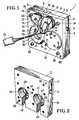
- This chopper device 1 shows a perspective view of the front of a chopper device 1 according to the invention.
- This chopper device 1 consists of two parts 2, 3 which can be connected to one another, the front part 3 having a smaller depth than the rear part 2.
- a lateral groove 4 which has a through-hole 5 in its lower end.
- a corresponding groove 6 on the opposite side of the rear part 2 can also be seen.
- the grooves 4, 6 are used to attach the chopper 1 in a housing, not shown.
- a bolt not shown, is inserted into the through hole 5.
- the front part 3 of the chopper device carries a Ferrari motor 7 which has two windings 8, 9 which surround legs of the magnets 10, 11.
- a Ferrari motor 7 which has two windings 8, 9 which surround legs of the magnets 10, 11.
- Electrical leads 18 - 21 are connected to these solderings 14 - 17, three leads 19, 20, 21 of which are led to a common coupler 22.
- the front and rear parts 2, 3 are connected to one another by means of Allen screws 23-26.
- holes 69, 75 are provided for receiving dowel pins.
- the front part 3 has a through-hole 27, behind which a chopper disk 28 can be seen.
- the through hole 27 is surrounded by an annular cut-out 29 in which three screws 30, 31, 32 are inserted.
- a through-hole corresponding to the through-hole 27 below the winding 9 is covered by a round plastic disk 33 which is fastened by means of screws 34, 35, 36 and nuts 37, 38, 39.
- FIG. 2 shows the rear of the rear part 2 of the chopper device 1.
- This rear side has two cylindrical bores 40, 41, each of which has an opening 42, 43, the depth of which corresponds to the depth of the bores 40, 41.
- In the respective bottom 44, 45 of the bores 40, 41 there is a through-hole 46, 47, behind which the chopper disk 28 passes.
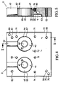
- FIG. 3 shows the rear view of the device shown in FIG. 2 or the top view of the rear part 2 when the front part 3 is removed in the illustration in FIG. 1.
- the deepest cut-outs are located in the central area and are provided with the reference numbers 48, 49, 50.
- the outer ends 51, 52, 53 of these cutouts 48, 49, 50 are approximately a quarter less deep.
- the cutouts 54, 55, which adjoin the projection 56, are considerably less deep.
- These cutouts 54, 55 serve to receive parts of the Ferrari motor 7, not shown, which have approximately the shape of the yokes of the magnets 10, 11, which are shown in FIG. 1.
- the projection 56 is only slightly higher than the central area of the cutouts 54, 55 and thus corresponds in terms of its depth to the edge area 57, 58 of the cutouts 54, 55.
- 59, 60, 61, 62 holes are indicated through which connecting screws can be inserted .
- All inner recesses are surrounded by an annular groove 63, which has only a small depth.
- With 122, 123 dowel pins are firmly pressed.
- FIG. 4 the device shown in Fig. 2 is shown again in plan view, but rotated by 180 °.
- the through-holes 46, 47 are surrounded by an annular edge 64, 65 which is slightly lower than the respective base 44, 45.
- the upper edges of the bores 40, 41 are chamfered, which is represented by the circular rings 66, 67.
- part 2 several bores 68-75, 59-62 are provided, of which only the bores 59-62 go completely through part 2.
- the two lateral edges of part 2 have bevels 76, 77.
- FIG. 5 shows a section VV through part 2 in FIG. 4.
- FIG. 6 shows a top view of the part 2 shown in FIG. 3, namely rotated by 180 °.
- Two sloping surfaces 81, 82 can be seen, which lie between the cutouts 48 and 52 or 48 and 50.
- the groove 53 serves to receive part of a bearing block.
- a section VII-VII through part 2 (FIG. 6) is shown in FIG. 7.
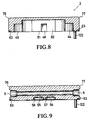
- FIG. 8 shows a section VIII-VIII through part 2
- FIG. 9 shows a section IX-IX through this part 2.
- a pressed dowel pin is designated 122 here.
- Fig. 10 the back of the front part 3 (Fig. 1) is shown.
- the chopper disk 85 is rotatably mounted just above a recess 86 by means of a shaft 87.
- the recess 27 recognizable in FIG. 1 can also be seen in FIG. 10.
- the plastic disk 33 can be seen behind a further recess 88.
- the counter bearing for the shaft 87 is located in a device 89 which has three legs 90, 91, 92. Each of these legs 90-92 is divided into several sections.
- the legs 90, 92 are screwed to the part 3 with ends 93, 94 angled forward and by means of screws 95, 96.
- the adjoining legs 95a, 96a lie at the same level with these ends 93, 94 and then merge into the ascending legs 97, 98. These ascending legs in turn open into the legs 99, 100, which are connected to one another by a connecting piece 101.
- the third arm 91 is constructed similarly to the other two arms 90, 92; however, its individual legs 102, 103, 104 are not angled to one another in the horizontal. In contrast, the legs 95a and 99 or 96a and 100 form an angle of approximately 45 degrees in the horizontal.
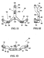
- FIG. 11 shows the device 89 again in a top view.
- 105 is a bore through which the shaft 87 (FIG. 10) is guided.
- Lugs 106, 107, 108 with bores 109, 110, 111 are provided for the arrangement of screws.
- FIG. 12 shows a side view of that shown in FIG. 11 Device 1. Only the legs 90 and 91 can be seen in this illustration.
- FIG. 13 shows a side view of the device 89, this device being tilted by 90 ° in comparison to the illustration in FIG. 11.
- the contact surfaces of the device 89 for the connection to the part 3 are consequently directed upwards and provided with the reference numbers 112, 113, 114.
- FIG. 14 shows a top view of part 3, with the ferrari motor removed. Where the legs of the ferrari motor surrounded by electrical windings are pushed through part 3, bores 115, 116 are provided. The legs of the Ferrari motor, which are not surrounded by windings, are pushed through holes 117, 118.
- the assembly of the parts 2, 3 to the device 1 shown in FIG. 1 takes place in such a way that the device 89 of the part 3 is introduced into the corresponding recesses 48-55 of the part 2. Then both parts are screwed together.
- the chopper 85 driven by the Ferrari motor 7 can now rotate in the space formed by the depression 78 in part 2 and by the depression 86 in part 3.
- cuvettes are inserted in the figures, which are filled, for example, with a gas to be analyzed.
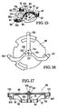
- FIG. 15 A variant of the invention is shown in FIG. 15, in which the chopper disk 85 forms a unit with the device 89. This makes it possible to remove this unit from parts 2, 3. In this solution, the device 89 no longer needs to be screwed to a part 2, 3 at the ends of its arms 90, 91, 92.
- This advantage is achieved by a component which has the shape of a vertical projection of the device 89 and of which the ends 130, 131, 132 can be seen in FIG. 15.
- the chopper disk 85 is thus arranged between the mentioned component and the device 89, the shaft 87 about which it rotates being mounted in both the component and the device 89.
- Fig. 16 shows a bottom view of the arrangement of Fig. 15, i. H. the component, which was arranged with its ends 130, 131, 132 below the device 89 in FIG. 15, now lies above this device 89.
- 137 denotes a screw which is surrounded by a nut 136. Both screw 137 and nut 136 serve to secure the bearing to the component in which shaft 87 rotates.
- threaded bores 133, 134, 135 are provided, into which screws can be inserted, with which this component can be attached to part 3.
- FIG. 17 shows a side view of the unit consisting of chopper disk 85, component and device 89. It can clearly be seen here that the chopper disk 85 is arranged just below the component.
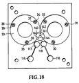
- FIG. 18 shows a variant of the device according to FIG. 14, which is suitable for receiving the unit consisting of chopper disk 85, component and device 89.
- This device has four bores, of which a central bore 141 serves to receive or include the screw 137 and the nut 136.
- This middle hole 141 is surrounded by three further bores 142, 143, 144, through which screws, not shown, can be inserted and screwed into the threaded bores 133 -135 of the component. 140 is a recess.
Landscapes
- Physics & Mathematics (AREA)
- General Physics & Mathematics (AREA)
- Spectroscopy & Molecular Physics (AREA)
- Optics & Photonics (AREA)
- Connection Of Motors, Electrical Generators, Mechanical Devices, And The Like (AREA)
- Motor Or Generator Frames (AREA)
- Photometry And Measurement Of Optical Pulse Characteristics (AREA)
- Investigating Or Analysing Materials By Optical Means (AREA)
Applications Claiming Priority (2)
| Application Number | Priority Date | Filing Date | Title |
|---|---|---|---|
| DE3723177 | 1987-07-14 | ||
| DE19873723177 DE3723177C2 (de) | 1987-07-14 | 1987-07-14 | Strahlungs-Zerhackereinrichtung |
Publications (2)
| Publication Number | Publication Date |
|---|---|
| EP0301251A2 true EP0301251A2 (fr) | 1989-02-01 |
| EP0301251A3 EP0301251A3 (fr) | 1990-12-27 |
Family
ID=6331504
Family Applications (1)
| Application Number | Title | Priority Date | Filing Date |
|---|---|---|---|
| EP19880110262 Withdrawn EP0301251A3 (fr) | 1987-07-14 | 1988-06-28 | Dispositif hacheur de rayonnement |
Country Status (2)
| Country | Link |
|---|---|
| EP (1) | EP0301251A3 (fr) |
| DE (1) | DE3723177C2 (fr) |
Cited By (1)
| Publication number | Priority date | Publication date | Assignee | Title |
|---|---|---|---|---|
| EP0386608A1 (fr) * | 1989-03-06 | 1990-09-12 | Siemens Aktiengesellschaft | Appareil pour modulation des rayons dans le trajet du faisceau d'analyseurs photométriques |
Families Citing this family (1)
| Publication number | Priority date | Publication date | Assignee | Title |
|---|---|---|---|---|
| DE3942821A1 (de) * | 1989-12-23 | 1991-06-27 | Rosemount Gmbh & Co | Strahlungs-choppereinrichtung mit einer von einem elektromotor angetriebenen chopperscheibe |
Family Cites Families (6)
| Publication number | Priority date | Publication date | Assignee | Title |
|---|---|---|---|---|
| AT348266B (de) * | 1973-10-30 | 1979-02-12 | Gao Ges Automation Org | Elektromechanischer taktgeber |
| DE2402865C2 (de) * | 1974-01-22 | 1983-03-24 | Hartmann & Braun Ag, 6000 Frankfurt | Lichtunterbrechungsvorrichtung für photometrische Meßgeräte |
| DE2608669C3 (de) * | 1976-03-03 | 1981-06-25 | Leybold-Heraeus GmbH, 5000 Köln | Vorrichtung zur Messung des optischen Absorptionsvermögen einer festen, flüssigen oder gasförmigen Probe |
| US4509819A (en) * | 1981-11-12 | 1985-04-09 | Lincoln Laser Company | Optical beam pulse generator |
| DD216323A1 (de) * | 1983-05-18 | 1984-12-05 | Magdeburg Medizinische Akad | Elektromechanischer licht-chopper fuer vier verschiedene wellenlaengen |
| JPS61199658U (fr) * | 1985-06-04 | 1986-12-13 |
-
1987
- 1987-07-14 DE DE19873723177 patent/DE3723177C2/de not_active Expired - Fee Related
-
1988
- 1988-06-28 EP EP19880110262 patent/EP0301251A3/fr not_active Withdrawn
Cited By (1)
| Publication number | Priority date | Publication date | Assignee | Title |
|---|---|---|---|---|
| EP0386608A1 (fr) * | 1989-03-06 | 1990-09-12 | Siemens Aktiengesellschaft | Appareil pour modulation des rayons dans le trajet du faisceau d'analyseurs photométriques |
Also Published As
| Publication number | Publication date |
|---|---|
| EP0301251A3 (fr) | 1990-12-27 |
| DE3723177C2 (de) | 1996-08-22 |
| DE3723177A1 (de) | 1989-01-26 |
Similar Documents
| Publication | Publication Date | Title |
|---|---|---|
| DE2743771C3 (de) | Werkzeug zur chirurgischen Vorbereitung der Implantation eines Implantats zur Befestigung von festsitzendem Zahnersatz | |
| DE3600781C3 (de) | Linsenhalterung | |
| WO1990015348A1 (fr) | Affaiblisseur pour faisceau laser | |
| DE19526727B4 (de) | Kugelumlaufvorrichtung mit externem Umlauf | |
| DE2307298A1 (de) | Optische mehrfachdurchgangs-absorptionkuevette | |
| DE3740744A1 (de) | Verfahren zur ueberfuehrung einer eingestellten lage von einer justiervorrichtung auf eine externe antriebseinheit und vorrichtung zur durchfuehrung des verfahrens | |
| DE19601964A1 (de) | Aufbau eines Lenkwinkelsensormuduls | |
| EP0271167B1 (fr) | Procédé pour ajuster l'entrefer de deux têtes magnétiques disposées sur un disque porte-tête et disque porte-tête comportant deux têtes magnétiques disposées sur lui | |
| DE3502138C2 (fr) | ||
| DE2527335C2 (de) | Vorrichtung zum Bewegen eines optischen Kopfes | |
| DE3327736A1 (de) | Spezial-winkelpruefkopf zur ultraschall-pruefung | |
| DE69319973T2 (de) | Diffraktionselement und optische Abtastkopfanordnung | |
| DE10048159A1 (de) | Gerät zur Aufnahme und Wiedergabe mittels einer optischen Platte (z.B.MD) und Verfahren zum Einbau seines Drehtellermotors | |
| DE1598089B2 (de) | Vorrichtung zur optischen Spektralanalyse | |
| DE4013743A1 (de) | Optischer abstandsschalter | |
| DE69122970T2 (de) | Automatisches gerät zur kolorimetrischen analyse von proben | |
| EP0301251A2 (fr) | Dispositif hacheur de rayonnement | |
| DE3305712A1 (de) | Sicherheitseinrichtung fuer einen zentrifugalabscheider | |
| DE1939865A1 (de) | Vorrichtung zum Lagern einer Bremsscheibe waehrend der Bearbeitung der Bremsflaechen | |
| DE4127051A1 (de) | Praezisionsgetriebe | |
| DE69016772T2 (de) | Einrichtung zum Tragen und Einstellen eines Spiegels eines Laserroboters und Laserroboter dafür. | |
| DE69219005T2 (de) | Optischer Kopfantrieb | |
| DE60224416T2 (de) | Mikrowellen-zirkulator mit derformierbarer membran | |
| WO1990007132A1 (fr) | Piege a lumiere exempt de retrodiffusion | |
| CH647326A5 (de) | Monochromator mit gitteranordnung. |
Legal Events
| Date | Code | Title | Description |
|---|---|---|---|
| PUAI | Public reference made under article 153(3) epc to a published international application that has entered the european phase |
Free format text: ORIGINAL CODE: 0009012 |
|
| AK | Designated contracting states |
Kind code of ref document: A2 Designated state(s): DE FR GB IT |
|
| PUAL | Search report despatched |
Free format text: ORIGINAL CODE: 0009013 |
|
| AK | Designated contracting states |
Kind code of ref document: A3 Designated state(s): DE FR GB IT |
|
| RAP1 | Party data changed (applicant data changed or rights of an application transferred) |
Owner name: ROSEMOUNT GMBH & CO. |
|
| STAA | Information on the status of an ep patent application or granted ep patent |
Free format text: STATUS: THE APPLICATION IS DEEMED TO BE WITHDRAWN |
|
| 18D | Application deemed to be withdrawn |
Effective date: 19910628 |