EP0301704B1 - Entraînement à deux vitesses pour alternateur - Google Patents
Entraînement à deux vitesses pour alternateur Download PDFInfo
- Publication number
- EP0301704B1 EP0301704B1 EP88305946A EP88305946A EP0301704B1 EP 0301704 B1 EP0301704 B1 EP 0301704B1 EP 88305946 A EP88305946 A EP 88305946A EP 88305946 A EP88305946 A EP 88305946A EP 0301704 B1 EP0301704 B1 EP 0301704B1
- Authority
- EP
- European Patent Office
- Prior art keywords
- shaft
- gear box
- output shaft
- speed
- gears
- Prior art date
- Legal status (The legal status is an assumption and is not a legal conclusion. Google has not performed a legal analysis and makes no representation as to the accuracy of the status listed.)
- Expired - Lifetime
Links
- 230000008878 coupling Effects 0.000 claims description 5
- 238000010168 coupling process Methods 0.000 claims description 5
- 238000005859 coupling reaction Methods 0.000 claims description 5
- 230000000452 restraining effect Effects 0.000 claims 5
- 238000006243 chemical reaction Methods 0.000 description 9
- 150000001875 compounds Chemical class 0.000 description 5
- 238000007789 sealing Methods 0.000 description 4
- 238000011217 control strategy Methods 0.000 description 2
- 238000012544 monitoring process Methods 0.000 description 2
- 230000001133 acceleration Effects 0.000 description 1
- 230000002411 adverse Effects 0.000 description 1
- 238000010276 construction Methods 0.000 description 1
- 230000003247 decreasing effect Effects 0.000 description 1
- 230000001419 dependent effect Effects 0.000 description 1
- 210000005069 ears Anatomy 0.000 description 1
- 239000000446 fuel Substances 0.000 description 1
- 239000000314 lubricant Substances 0.000 description 1
- 238000000034 method Methods 0.000 description 1
- 239000007787 solid Substances 0.000 description 1
Images
Classifications
-
- H—ELECTRICITY
- H02—GENERATION; CONVERSION OR DISTRIBUTION OF ELECTRIC POWER
- H02K—DYNAMO-ELECTRIC MACHINES
- H02K7/00—Arrangements for handling mechanical energy structurally associated with dynamo-electric machines, e.g. structural association with mechanical driving motors or auxiliary dynamo-electric machines
- H02K7/10—Structural association with clutches, brakes, gears, pulleys or mechanical starters
-
- F—MECHANICAL ENGINEERING; LIGHTING; HEATING; WEAPONS; BLASTING
- F02—COMBUSTION ENGINES; HOT-GAS OR COMBUSTION-PRODUCT ENGINE PLANTS
- F02B—INTERNAL-COMBUSTION PISTON ENGINES; COMBUSTION ENGINES IN GENERAL
- F02B67/00—Engines characterised by the arrangement of auxiliary apparatus not being otherwise provided for, e.g. the apparatus having different functions; Driving auxiliary apparatus from engines, not otherwise provided for
- F02B67/04—Engines characterised by the arrangement of auxiliary apparatus not being otherwise provided for, e.g. the apparatus having different functions; Driving auxiliary apparatus from engines, not otherwise provided for of mechanically-driven auxiliary apparatus
-
- F—MECHANICAL ENGINEERING; LIGHTING; HEATING; WEAPONS; BLASTING
- F16—ENGINEERING ELEMENTS AND UNITS; GENERAL MEASURES FOR PRODUCING AND MAINTAINING EFFECTIVE FUNCTIONING OF MACHINES OR INSTALLATIONS; THERMAL INSULATION IN GENERAL
- F16H—GEARING
- F16H3/00—Toothed gearings for conveying rotary motion with variable gear ratio or for reversing rotary motion
- F16H3/44—Toothed gearings for conveying rotary motion with variable gear ratio or for reversing rotary motion using gears having orbital motion
- F16H3/46—Gearings having only two central gears, connected by orbital gears
- F16H3/48—Gearings having only two central gears, connected by orbital gears with single orbital gears or pairs of rigidly-connected orbital gears
- F16H3/52—Gearings having only two central gears, connected by orbital gears with single orbital gears or pairs of rigidly-connected orbital gears comprising orbital spur gears
- F16H3/56—Gearings having only two central gears, connected by orbital gears with single orbital gears or pairs of rigidly-connected orbital gears comprising orbital spur gears both central gears being sun gears
-
- H—ELECTRICITY
- H02—GENERATION; CONVERSION OR DISTRIBUTION OF ELECTRIC POWER
- H02K—DYNAMO-ELECTRIC MACHINES
- H02K7/00—Arrangements for handling mechanical energy structurally associated with dynamo-electric machines, e.g. structural association with mechanical driving motors or auxiliary dynamo-electric machines
- H02K7/10—Structural association with clutches, brakes, gears, pulleys or mechanical starters
- H02K7/1004—Structural association with clutches, brakes, gears, pulleys or mechanical starters with pulleys
-
- H—ELECTRICITY
- H02—GENERATION; CONVERSION OR DISTRIBUTION OF ELECTRIC POWER
- H02K—DYNAMO-ELECTRIC MACHINES
- H02K7/00—Arrangements for handling mechanical energy structurally associated with dynamo-electric machines, e.g. structural association with mechanical driving motors or auxiliary dynamo-electric machines
- H02K7/10—Structural association with clutches, brakes, gears, pulleys or mechanical starters
- H02K7/102—Structural association with clutches, brakes, gears, pulleys or mechanical starters with friction brakes
- H02K7/1021—Magnetically influenced friction brakes
- H02K7/1023—Magnetically influenced friction brakes using electromagnets
- H02K7/1025—Magnetically influenced friction brakes using electromagnets using axial electromagnets with generally annular air gap
-
- H—ELECTRICITY
- H02—GENERATION; CONVERSION OR DISTRIBUTION OF ELECTRIC POWER
- H02K—DYNAMO-ELECTRIC MACHINES
- H02K7/00—Arrangements for handling mechanical energy structurally associated with dynamo-electric machines, e.g. structural association with mechanical driving motors or auxiliary dynamo-electric machines
- H02K7/10—Structural association with clutches, brakes, gears, pulleys or mechanical starters
- H02K7/116—Structural association with clutches, brakes, gears, pulleys or mechanical starters with gears
Definitions
- the present invention relates to a two-speed alternator drive unit to address this problem.
- the present invention relates to a two-speed gear box adapted to be mounted on the face of an automotive alternator to increase the speed of the alternator on demand.
- the alternator drive uses a compact gear train and clutch assembly mounted onto the face of the alternator to achieve the dual-speed operation.
- the engaged mode for example a two-to-one internal gear ratio, is utilised to achieve the required alternator speed at low engine speeds.
- the device then shifts to the disengaged mode at a predetermined engine speed, which results in a direct drive of a one-to-one internal ratio; thus preventing excessive alternator speeds at high engine speeds.
- the end result is a drive that provides the automobile with the required output current at low engine speeds, but does not cause alternator over-speed at high engine speeds.
- WO 85/01335 discloses, inter alia, a two-speed gear box in accordance with the prior art portion of claim 1.
- This prior proposal utilises a specially controlled friction coupling for ensuring simultaneous rotation of the input and output shafts.
- the present invention provides automatic coupling without need for a separate clutch drive to be provided.
- the present invention utilises a one way clutch providing a positive direct connection between the input and output shafts whenever the planetary gear train is not operating assisting in the provision of a compact arrangement which can be mounted on the face of the accessory.
- US-A-4 412 460 discloses the use of a one way coupling in an accessory drive, utilising a planetary gear train, the gear train itself utilises an outer annular gear with the result of increased bearing loads as compared with the gear box of the present invention.
- the one-way clutch drives the output shaft at the same speed as the input shaft; the one-way clutch allowing the output shaft to overspeed the input shaft when the brake band engages the planet carrier.
- a vacuum or other suitably actuated clutch assembly adds negligible electrical and no mechanical loads to the engine, and engine drag due to alternator inertia may be decreased by using a smaller alternator with this device. Also, low bearing and gear speeds of the device provide for quiet, durable operation. Control of the alternator drive could be provided by the vehicle engine control module with a user-tailored control strategy.
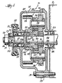
- Figure 1 discloses a two-speed gear box 10 that is appropriately mounted onto the end of an accessory 11, such as an alternator for an automotive vehicle engine.
- This gear box is mounted on the face of an alternator to control the alternator speeds between 3,000 and 15,000 rpm.
- the gear box consists of a housing 12 which may be suitably formed of two parts to allow ease of assembly and accessability, the two parts having several lugs or ears 13 with aligned passages to receive mounting bolts 14 to secure the housing to the accessory.
- the forward end of the housing includes a flanged central opening 15 having spaced bearings 16, 16 rotatably receiving an input shaft 17; the shaft having a reduced forward end 18 to receive the hub 19 of a drive pulley 21 for a drive belt 22 from the engine crankshaft (not shown).
- the drive pulley 21 is connected to rotate with the input shaft end 18 through a splined connection 23, and a nut 24 and washer 25 engage the pulley 19 to mount the hub onto the input shaft; the nut engaging the threaded outer end 26 of the input shaft 17.
- a generally cylindrical planet carrier 29 has a cylindrical hub 31 rotatably mounted on said sleeve shaft 27 through a plurality of needle bearings 32.
- An outer cylindrical surface 33 is connected to the hub through a radial flange 34, the flange carrying a plurality of carrier shafts 35 for compound planet gears 36; the planet gears being rotatably supported on shafts 35 through needle bearings 37.
- the compound gearing includes a plurality of first planet gears 38 intermeshing with the input sun gear 28, and a plurality of second planet gears 39 meshing with a second sun gear 41.
- the first and second planet gears are integral, however, the first planet gears are of a smaller pitch diameter, and thus a smaller number of teeth, than the second planet gears to provide a desired drive ratio.
- the second or output sun gear 41 is splined to an output shaft 42 which is rotatably mounted in a bearing 43 to project into and drive the accessory, such as an automobile alternator.
- Suitable sealing means 44 for the input shaft 17 is mounted in the flanged opening 15 between the bearings 16, 16, and suitable sealing means 45 is mounted in a central opening 46 in the housing 12 to sealingly engage the output shaft 42 adjacent the bearing 43.
- a brake band 47 encompasses the outer cylindrical surface 33 of the planet carrier 29 and is adapted to engage said surface to alter the drive ratio of the gear box. Also, a one-way clutch 48 is positioned between bearings 49, 49 between the sleeve shaft 27 and the inner reduced end 51 of the output shaft 42. Suitable vacuum means (not shown) is utilized to engage or disengage the brake band 47.
- the speed of the alternator 11 can be increased by applying vacuum to the actuator which engages the brake band 47 with the planet carrier surface 33 stopping the rotation of the planet carrier.
- the gear train reacts like a parallel countershaft arrangement with the planet carrier 29 being held by the brake band 47.
- the input sun gear 28 turns clockwise driving the first set of planet gears 38 counterclockwise.
- the second set of planet gears 39 are connected to the first set of planet gears 38 and turn in the same direction and at the same speed as the first set of planet gears.
- the second set of planet gears drive the output sun gear 41 clockwise, the same direction as the input sun gear 28.
- the speed of the output shaft 42 equals the input shaft speed times the gear ratios of the first and second planet gears.
- the vacuum is released and a spring (not shown) disengages the brake band 47 from the planet carrier surface 33.
- the planet carrier 29 turns clockwise, the same direction as the input shaft 17, and the planet gears 38 and 39 no longer transmit torque to the output sun gear 41.
- the output shaft 42 slows down until its speed equals that of the input shaft 17.
- the one-way clutch 48 now drives the output shaft 42 clockwise at the same speed as the input shaft 17.
- the planet carrier 29 and both sets of planet gears 38, 39 rotate as a solid unit at the same speed as the input shaft 17, so there is no relative motion between the gears.
- the one-way clutch 48 allows the output shaft 42 to overspeed the input shaft 17 when the brake band 47 engages the cylindrical surface 33 of the planet carrier 29.
- the output shaft speed for this device follows the equation where O S equals the output shaft speed, I S equals the input shaft speed, PD IS is the pitch diameter of the input sun gear, PD PG1 is the pitch diameter of the first set of planet gears, PD PG2 is the pitch diameter of the second set of planet gears, and PD OS is the pitch diameter of the output sun gear.
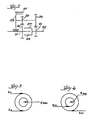
- Figure 2 shows an alternative arrangement of this basic gear train concept with another possible location of the one-way clutch (not claimed) and the brake band.
- Figure 2 discloses a schematic showing of the gear train arrangement similar to Figure 1 except the input shaft 17 projects into a sleeve shaft 27′ on the inner end of output shaft 42.
- the unique feature of the present invention is the use of planetary type of gear arrangement with two sun gears, compound planet gears, but no ring gear. This allows several advantages over the standard planetary gears that use a ring gear:
- Figure 3 illustrates a conventional planetary gear arrangement with a sun gear, ring gear and planetary gears.
- the bearings for the planet gears such as bearings 37 shown in Figure 1, have a reaction load (R BRG ) that is equal to the sum of the reaction load on the sun gear (R S ) and the reaction load on the ring gear (R R ).
- the reaction load on the bearings (R BRG ) is the difference between the reaction load of the second sun gear (R S2 ) and the reaction load of the first sun gear (R S1 ).
- the reaction loads of the sun gears tend to cancel each other instead of adding together.
- the two-speed alternator drive of the present invention is envisioned as being controlled by the engine control module of the vehicle.
- the final control strategy would have to be tailored to the particular application, and the decision to shift into the engaged mode could be based on one or more of the following conditions:
- the alternator drive could operate in the engaged mode only when necessary by monitoring the engine speed and the battery discharge rate. By monitoring the throttle position, the operation of the device in its engaged mode could be prevented under heavy engine accelerations. This would minimize any alternator drag on the engine at that time, and the time delay would help prevent unnecessary operating mode changes and prevent the device from operating in the engaged mode during engine start up.
- the decision to disengage the device could be based on the following conditions:
- the device could be signaled to a disengaged mode by any of the above conditions to prevent the alternator from being run at excessive speeds.
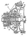
- FIG. 5 discloses an alternative embodiment of two-gear drive 61 wherein like parts have the same numeral with the addition of a script a.
- the accessory drive shaft 42a extends from its housing 11a substantially completely through the gear housing 12a to a point short of the end of sleeve shaft 62.
- the housing 12a consists of a rear member 63 having fastening lugs 64 to receive bolts 65 securing the member to the accessory drive 11a, a front housing member 66 secured to the rear member by bolts 67 and an intermediate member 68 secured to the front member by bolts 69.
- the rear member 63 has a central opening 71 receiving the inner axial flange 72 of the intermediate member 68, the flange carrying sealing means 45a for the shaft 42a.
- the front housing member 66 has a central opening defined by axial flange 73 carrying sealing means 44a and a bearing 16a for the sleeve shaft 62.
- a pulley 21a for the drive belt 22a to the engine crankshaft (not shown) has a hub 19a secured to the sleeve shaft by suitable means, such as a key and keyway.
- suitable means such as a key and keyway.
- a cap 77 closes the open end of sleeve shaft 62 to retain lubricant in the bearings.
- the inner end of the sleeve shaft terminates in a first sun gear 28a while a second sun gear 41a is secured for rotation with shaft 42a.
- a planet carrier 29a includes a cylindrical hub 31a rotatably mounted on the shaft 42a by needle bearings 32a and a cylindrical outer flange or surface 33a connected to the hub by a radial flange 34a carrying a plurality of shafts 35a for compound planet gears 36a rotatably mounted on the shafts by needle bearings 37a.
- Each compound planet gear 36a includes a first planet gear 38a meshing with sun gear 28a and an integral second planet gear 39a meshing with sun gear 41a; the first planet gear having a smaller pitch diameter relative to the second planet gear.
- a brake band 47a encompasses the outer surface 33a and is suitably actuated to engage and halt rotation of the carrier.
- This embodiment operates in substantially the same manner as the embodiment of Figure 1; the one-way clutch 76 being so oriented as to allow the shaft 42a to overrun the sleeve shaft 62.
Landscapes
- Engineering & Computer Science (AREA)
- General Engineering & Computer Science (AREA)
- Mechanical Engineering (AREA)
- Power Engineering (AREA)
- Chemical & Material Sciences (AREA)
- Combustion & Propulsion (AREA)
- Structure Of Transmissions (AREA)
- Pulleys (AREA)
Claims (7)
Applications Claiming Priority (2)
| Application Number | Priority Date | Filing Date | Title |
|---|---|---|---|
| US72485 | 1987-07-13 | ||
| US07/072,485 US4862770A (en) | 1987-07-13 | 1987-07-13 | Two-speed alternator drive |
Publications (2)
| Publication Number | Publication Date |
|---|---|
| EP0301704A1 EP0301704A1 (fr) | 1989-02-01 |
| EP0301704B1 true EP0301704B1 (fr) | 1991-07-17 |
Family
ID=22107903
Family Applications (1)
| Application Number | Title | Priority Date | Filing Date |
|---|---|---|---|
| EP88305946A Expired - Lifetime EP0301704B1 (fr) | 1987-07-13 | 1988-06-30 | Entraînement à deux vitesses pour alternateur |
Country Status (4)
| Country | Link |
|---|---|
| US (1) | US4862770A (fr) |
| EP (1) | EP0301704B1 (fr) |
| JP (1) | JPS6430948A (fr) |
| DE (1) | DE3863711D1 (fr) |
Families Citing this family (48)
| Publication number | Priority date | Publication date | Assignee | Title |
|---|---|---|---|---|
| US5011464A (en) * | 1990-03-23 | 1991-04-30 | Sundstrand Corporation | Two-speed automatic transmission |
| US5122099A (en) * | 1991-04-04 | 1992-06-16 | Borg-Warner Automotive, Inc. | Two-speed planetary friction accessory drive |
| US5139468A (en) * | 1991-11-08 | 1992-08-18 | Borg-Warner Automotive, Inc. | Two speed engine accessory drive with plastic planet gears |
| DE69220467T2 (de) * | 1991-12-27 | 1997-10-16 | Tochigi Fuji Sangyo Kk | Zahnradgetriebe |
| US5328419A (en) * | 1992-04-10 | 1994-07-12 | Borg-Warner Automotive, Inc. | Two-speed alternator drive |
| JP3427901B2 (ja) * | 1992-07-28 | 2003-07-22 | 日本電信電話株式会社 | メモリ内容回復装置 |
| GB9218847D0 (en) * | 1992-09-05 | 1992-10-21 | Jaguar Cars | Dual ratio drives |
| EP0591617A3 (fr) * | 1992-10-08 | 1995-02-15 | Freudenberg Carl Fa | Transmission à deux vitesses avec changement de vitesse à frein. |
| DE4339218C2 (de) * | 1993-11-18 | 1996-07-18 | Freudenberg Carl Fa | Planetengetriebe für den Antrieb von Nebenaggregaten |
| IL120154A0 (en) | 1996-06-23 | 1997-06-10 | Daniels Johnny | Automotive accessory driving system particularly for air-conditioning units |
| US6082340A (en) * | 1998-03-18 | 2000-07-04 | Heimark; Charles L. | Two-speed supercharger |
| DE19822426C2 (de) * | 1998-05-19 | 2000-03-23 | Daimler Chrysler Ag | Antriebsvorrichtung für Nebenaggregate einer Hubkolbenbrennkraftmaschine |
| EP1047874B1 (fr) * | 1998-11-14 | 2004-07-28 | Robert Bosch Gmbh | Moteur electrique avec engrenage |
| JP3712926B2 (ja) * | 2000-08-28 | 2005-11-02 | 三菱電機株式会社 | 車両用交流発電機 |
| US6427735B1 (en) | 2001-02-26 | 2002-08-06 | One World Technologies, Inc. | Multi-speed surface planer and method of manufacture thereof |
| EP1237256A3 (fr) * | 2001-02-28 | 2004-11-10 | Hitachi, Ltd. | Mécanisme de transmission pour alternateur pour véhicule automobile |
| KR20040045741A (ko) * | 2002-11-25 | 2004-06-02 | 현대자동차주식회사 | 알터네이터용 진공펌프 |
| US7316628B2 (en) * | 2004-01-13 | 2008-01-08 | The Gates Corporation Ip Law Dept. | Two speed transmission and belt drive system |
| JP4742822B2 (ja) * | 2005-11-10 | 2011-08-10 | 株式会社デンソー | 車両用交流発電機 |
| US7534188B2 (en) * | 2006-01-27 | 2009-05-19 | Borgwarner Inc. | Transfer case input shaft brake system |
| US20080096713A1 (en) * | 2006-10-10 | 2008-04-24 | Beson Thomas W | Overdrive and underdrive power converting modulators, and methods |
| CN101436803B (zh) * | 2007-11-16 | 2011-12-14 | 叶桂顺 | 无刷电机齿轮加机油减速传动机构 |
| DE112011100447A5 (de) * | 2010-02-04 | 2013-04-04 | Magna Powertrain Ag & Co. Kg | Antriebsvorrichtung für ein nebenaggregat |
| RU2440524C1 (ru) * | 2010-08-02 | 2012-01-20 | Равиль Гафиевич Хадеев | Адаптивная трансмиссия для транспортного средства |
| KR101159835B1 (ko) * | 2010-11-04 | 2012-06-26 | 이남수 | 무단 변속기 |
| FR2984285B1 (fr) * | 2011-12-14 | 2015-05-01 | Lesaffre & Cie | Materiau et conditionnement pour la conservation des levures |
| RU2531427C2 (ru) * | 2012-10-19 | 2014-10-20 | Равиль Гафиевич Хадеев | Двухступенчатый механизм сцепления |
| CN103267092A (zh) * | 2013-05-30 | 2013-08-28 | 王玉鸿 | 三排行星齿轮能做五至十六档的变速器 |
| KR101490948B1 (ko) * | 2013-09-09 | 2015-02-12 | 현대자동차 주식회사 | 차량용 댐퍼 풀리 조립체 |
| US20150130315A1 (en) * | 2013-11-14 | 2015-05-14 | Nidec Motor Corporation | Motor/generator with combination clutch and bearing arrangement |
| CN103762778B (zh) * | 2014-02-12 | 2016-01-20 | 浙江三星机电股份有限公司 | 一种带减速装置的无刷直流电机 |
| JP6137148B2 (ja) * | 2014-11-28 | 2017-05-31 | マツダ株式会社 | モータジェネレータ装置 |
| US9500267B2 (en) | 2015-02-27 | 2016-11-22 | E-Aam Driveline Systems Ab | Drive module with compact differential mechanism |
| DE102015006023B4 (de) * | 2015-05-13 | 2020-08-06 | Sew-Eurodrive Gmbh & Co Kg | Getriebe mit einer in einem Flanschteil mittels eines Lagers gelagerten eintreibenden Welle und einer Kupplungshülse |
| CN104879474B (zh) * | 2015-06-28 | 2017-08-11 | 管继尧 | 一种双速传动轮 |
| EP3445987B1 (fr) | 2016-05-27 | 2021-07-07 | Cummins, Inc. | Systèmes de moteur principal comprenant des organes d'entraînement multi-accessoires et leurs procédés de commande |
| US9958049B1 (en) | 2017-05-15 | 2018-05-01 | E-Aam Driveline Systems Ab | Electric drive module with Ravigneaux gearset |
| KR102348117B1 (ko) | 2017-06-07 | 2022-01-07 | 현대자동차주식회사 | 알터네이터 구동장치 및 그의 제어방법 |
| JP2019002319A (ja) * | 2017-06-14 | 2019-01-10 | カルソニックカンセイ株式会社 | ハイブリッド圧縮機 |
| US10316946B2 (en) | 2017-10-13 | 2019-06-11 | E-Aam Driveline Systems Ab | Two mode electric drive module with Ravigneaux gearset |
| CN111417537B (zh) * | 2017-12-29 | 2023-12-12 | 沃尔沃卡车集团 | 用于发动机装置的驱动系统 |
| CN110158273B (zh) | 2018-02-14 | 2023-02-28 | 菲舍尔和佩克尔应用有限公司 | 用于洗涤机的集成电机和齿轮箱驱动系统 |
| US11441481B2 (en) | 2018-05-24 | 2022-09-13 | Ford Global Technologies, Llc | Mechanism for a two-speed engine accessory drive system in a vehicle |
| CN110707610B (zh) * | 2019-11-07 | 2020-11-20 | 徐州领君自动化设备有限公司 | 一种新型剥线机单轴传动皮带送线机构 |
| TWI755041B (zh) * | 2020-08-27 | 2022-02-11 | 姚立和 | 周轉式變速機構 |
| CN112537189A (zh) * | 2020-12-14 | 2021-03-23 | 重庆虎溪电机工业有限责任公司 | 一种无人车用电驱动装置 |
| KR102978956B1 (ko) * | 2023-06-15 | 2026-06-17 | 에이치엘만도 주식회사 | 전기 이동수단의 구동 모터 시스템 및 이를 포함하는 구동 시스템 |
| EP4729773A1 (fr) * | 2024-10-18 | 2026-04-22 | Deere & Company | Compresseur d'air pour une installation de gonflage de pneus |
Citations (2)
| Publication number | Priority date | Publication date | Assignee | Title |
|---|---|---|---|---|
| US4412460A (en) * | 1980-06-23 | 1983-11-01 | S.A. Automobiles Citroen | Two-speed couplings |
| WO1985001335A1 (fr) * | 1983-09-15 | 1985-03-28 | Zahnradfabrik Friedrichshafen Ag | Engrenage commutable en charge |
Family Cites Families (26)
| Publication number | Priority date | Publication date | Assignee | Title |
|---|---|---|---|---|
| US1274056A (en) * | 1917-08-20 | 1918-07-30 | Jandus Arc Lamp & Electric Company Ltd | Differential gearing. |
| US1297439A (en) * | 1917-10-12 | 1919-03-18 | Auto Speed Gear Mfg Co | Differential gearing. |
| US1406119A (en) * | 1920-07-30 | 1922-02-07 | Kyokuto Jidoshia Kogyo Co Ltd | Coupling device for power-transmission mechanism and brake apparatus for an automobile |
| US1649050A (en) * | 1924-09-16 | 1927-11-15 | Winch Howard James | Variable gear |
| US1950694A (en) * | 1931-06-01 | 1934-03-13 | Roy W Parkinson | Clutch for motor vehicles |
| US2477024A (en) * | 1945-08-18 | 1949-07-26 | George C Webster | Adjustable speed gearing mechanism |
| US2690086A (en) * | 1951-08-21 | 1954-09-28 | Clark Equipment Co | Transmission |
| US2901073A (en) * | 1955-11-09 | 1959-08-25 | Fichtel & Sachs Ag | Bearing arrangement for centrifugal and axially engaging clutches |
| US3037600A (en) * | 1959-06-08 | 1962-06-05 | Heckethorn Mfg & Supply Compan | Two speed accessory drive |
| DE1196924B (de) * | 1961-10-30 | 1965-07-15 | Pulsgetriebe Erich Friedrich P | Lastschaltvorrichtung fuer Planetengruppen-getriebe |
| US3374692A (en) * | 1964-10-12 | 1968-03-26 | Benjamin M. Kitch | Automatic transmission |
| US3425300A (en) * | 1965-07-05 | 1969-02-04 | Toyota Motor Co Ltd | Speed change gearing devices |
| US3747731A (en) * | 1972-01-26 | 1973-07-24 | Borg Warner | Constant speed centrifugal clutch |
| US3954028A (en) * | 1973-11-05 | 1976-05-04 | Caterpillar Tractor Co. | Compact planetary drive transmission providing one-to-one drive ratio in either direction |
| US4020711A (en) * | 1975-06-11 | 1977-05-03 | Borg-Warner Corporation | Drive system |
| US4147242A (en) * | 1976-09-14 | 1979-04-03 | Nissan Motor Company, Limited | Power transmission for use in industrial vehicle driveline and equipped with fluid actuated clutches |
| US4080843A (en) * | 1976-12-13 | 1978-03-28 | Borg-Warner Corporation | Vehicle accessory drive |
| JPS5949051B2 (ja) * | 1978-02-10 | 1984-11-30 | 株式会社日立製作所 | 高速回転体の給排気装置 |
| US4265135A (en) * | 1978-11-27 | 1981-05-05 | Borg-Warner Corporation | Automotive accessory drive |
| DE2946140A1 (de) * | 1979-11-15 | 1981-05-21 | Robert Bosch Gmbh, 7000 Stuttgart | Bordnetzsystem fuer kraftfahrzeuge |
| US4502345A (en) * | 1980-02-07 | 1985-03-05 | Borg-Warner Corporation | Accessory drive system |
| FI67749C (fi) * | 1981-06-04 | 1985-05-10 | Waertsilae Oy Ab | Variatorvaexel foer dieseldriven synkrongenerator |
| JPS58175999A (ja) * | 1982-04-07 | 1983-10-15 | Mitsubishi Electric Corp | 車両用発電機装置 |
| JPS61144466A (ja) * | 1984-12-17 | 1986-07-02 | Mitsubishi Electric Corp | エンジンの補機駆動装置 |
| US4667537A (en) * | 1985-05-30 | 1987-05-26 | Canadian Fram Limited | Two speed accessory drive |
| DE3612046A1 (de) * | 1986-04-10 | 1987-10-15 | Ford Werke Ag | Rollen- oder klemmkoerper-freilauf, insbesondere fuer automatik-getriebe fuer kraftfahrzeuge |
-
1987
- 1987-07-13 US US07/072,485 patent/US4862770A/en not_active Expired - Lifetime
-
1988
- 1988-06-30 DE DE8888305946T patent/DE3863711D1/de not_active Expired - Lifetime
- 1988-06-30 EP EP88305946A patent/EP0301704B1/fr not_active Expired - Lifetime
- 1988-07-13 JP JP63174857A patent/JPS6430948A/ja active Pending
Patent Citations (2)
| Publication number | Priority date | Publication date | Assignee | Title |
|---|---|---|---|---|
| US4412460A (en) * | 1980-06-23 | 1983-11-01 | S.A. Automobiles Citroen | Two-speed couplings |
| WO1985001335A1 (fr) * | 1983-09-15 | 1985-03-28 | Zahnradfabrik Friedrichshafen Ag | Engrenage commutable en charge |
Also Published As
| Publication number | Publication date |
|---|---|
| DE3863711D1 (de) | 1991-08-22 |
| EP0301704A1 (fr) | 1989-02-01 |
| US4862770A (en) | 1989-09-05 |
| JPS6430948A (en) | 1989-02-01 |
Similar Documents
| Publication | Publication Date | Title |
|---|---|---|
| US4862770A (en) | Two-speed alternator drive | |
| US5558175A (en) | Hybrid power transmission | |
| US5258651A (en) | Electrically biased starting reaction device for a power transmission | |
| JP4472192B2 (ja) | 自動車用駆動システム | |
| EP1316721B1 (fr) | Système de commande de moteur automobile à combustion | |
| US6910453B2 (en) | Automotive internal combustion engine control system | |
| EP0317214B1 (fr) | Entraînement d'accessoire à deux vitesses et à commande par force centrifuge | |
| US20040164560A1 (en) | Transmission gear apparatus for motor vehicle | |
| US4494637A (en) | Power transmission system for vehicles | |
| US5564992A (en) | Torque maximizing controlled slip gear drive | |
| US4909200A (en) | Combined manual and power driven engine starter | |
| JPH05209662A (ja) | 2速伝動装置 | |
| US5685404A (en) | Power transmission system for use with a manual transmission including a torque convertor | |
| US4603754A (en) | Drive system for engine-driven light vehicles | |
| US8113089B2 (en) | Engine starting apparatus | |
| JPH0379585B2 (fr) | ||
| WO2007116220A1 (fr) | Systèmes de transmission | |
| GB2156016A (en) | Epicyclic reduction gear with an electromagnetic clutch | |
| US6569048B1 (en) | Tandem torque converter | |
| US6334307B1 (en) | Fluid coupling | |
| US20120103117A1 (en) | Transmission device for an auxiliary or accessory of a variable-speed engine, an engine equipped therewith and uses thereof | |
| EP1459931B1 (fr) | Engrenage planétaire pour véhicule à moteur | |
| US5772548A (en) | Power train of automatic transmission for vehicle | |
| JPH11153038A (ja) | 車両の内燃機関と電動発電機の複合装置 | |
| EP3730329B1 (fr) | Dispositif de train de transmission de véhicule |
Legal Events
| Date | Code | Title | Description |
|---|---|---|---|
| PUAI | Public reference made under article 153(3) epc to a published international application that has entered the european phase |
Free format text: ORIGINAL CODE: 0009012 |
|
| AK | Designated contracting states |
Kind code of ref document: A1 Designated state(s): DE FR GB IT |
|
| 17P | Request for examination filed |
Effective date: 19890307 |
|
| 17Q | First examination report despatched |
Effective date: 19900215 |
|
| GRAA | (expected) grant |
Free format text: ORIGINAL CODE: 0009210 |
|
| AK | Designated contracting states |
Kind code of ref document: B1 Designated state(s): DE FR GB IT |
|
| ITF | It: translation for a ep patent filed | ||
| REF | Corresponds to: |
Ref document number: 3863711 Country of ref document: DE Date of ref document: 19910822 |
|
| ET | Fr: translation filed | ||
| PGFP | Annual fee paid to national office [announced via postgrant information from national office to epo] |
Ref country code: GB Payment date: 19920330 Year of fee payment: 5 |
|
| PLBE | No opposition filed within time limit |
Free format text: ORIGINAL CODE: 0009261 |
|
| STAA | Information on the status of an ep patent application or granted ep patent |
Free format text: STATUS: NO OPPOSITION FILED WITHIN TIME LIMIT |
|
| 26N | No opposition filed | ||
| PG25 | Lapsed in a contracting state [announced via postgrant information from national office to epo] |
Ref country code: GB Effective date: 19930630 |
|
| GBPC | Gb: european patent ceased through non-payment of renewal fee |
Effective date: 19930630 |
|
| PG25 | Lapsed in a contracting state [announced via postgrant information from national office to epo] |
Ref country code: IT Free format text: LAPSE BECAUSE OF NON-PAYMENT OF DUE FEES Effective date: 20050630 |
|
| PGFP | Annual fee paid to national office [announced via postgrant information from national office to epo] |
Ref country code: DE Payment date: 20070629 Year of fee payment: 20 |
|
| PGFP | Annual fee paid to national office [announced via postgrant information from national office to epo] |
Ref country code: FR Payment date: 20070605 Year of fee payment: 20 |