EP0301809B1 - Videoplattenspieler - Google Patents
Videoplattenspieler Download PDFInfo
- Publication number
- EP0301809B1 EP0301809B1 EP88306875A EP88306875A EP0301809B1 EP 0301809 B1 EP0301809 B1 EP 0301809B1 EP 88306875 A EP88306875 A EP 88306875A EP 88306875 A EP88306875 A EP 88306875A EP 0301809 B1 EP0301809 B1 EP 0301809B1
- Authority
- EP
- European Patent Office
- Prior art keywords
- disc
- recorded
- disc player
- video
- track area
- Prior art date
- Legal status (The legal status is an assumption and is not a legal conclusion. Google has not performed a legal analysis and makes no representation as to the accuracy of the status listed.)
- Expired
Links
Images


Classifications
-
- H—ELECTRICITY
- H04—ELECTRIC COMMUNICATION TECHNIQUE
- H04N—PICTORIAL COMMUNICATION, e.g. TELEVISION
- H04N9/00—Details of colour television systems
- H04N9/79—Processing of colour television signals in connection with recording
- H04N9/7921—Processing of colour television signals in connection with recording for more than one processing mode
- H04N9/7925—Processing of colour television signals in connection with recording for more than one processing mode for more than one standard
-
- G—PHYSICS
- G11—INFORMATION STORAGE
- G11B—INFORMATION STORAGE BASED ON RELATIVE MOVEMENT BETWEEN RECORD CARRIER AND TRANSDUCER
- G11B27/00—Editing; Indexing; Addressing; Timing or synchronising; Monitoring; Measuring tape travel
- G11B27/10—Indexing; Addressing; Timing or synchronising; Measuring tape travel
- G11B27/102—Programmed access in sequence to addressed parts of tracks of operating record carriers
- G11B27/105—Programmed access in sequence to addressed parts of tracks of operating record carriers of operating discs
-
- G—PHYSICS
- G11—INFORMATION STORAGE
- G11B—INFORMATION STORAGE BASED ON RELATIVE MOVEMENT BETWEEN RECORD CARRIER AND TRANSDUCER
- G11B27/00—Editing; Indexing; Addressing; Timing or synchronising; Monitoring; Measuring tape travel
- G11B27/10—Indexing; Addressing; Timing or synchronising; Measuring tape travel
- G11B27/19—Indexing; Addressing; Timing or synchronising; Measuring tape travel by using information detectable on the record carrier
- G11B27/28—Indexing; Addressing; Timing or synchronising; Measuring tape travel by using information detectable on the record carrier by using information signals recorded by the same method as the main recording
- G11B27/30—Indexing; Addressing; Timing or synchronising; Measuring tape travel by using information detectable on the record carrier by using information signals recorded by the same method as the main recording on the same track as the main recording
- G11B27/3027—Indexing; Addressing; Timing or synchronising; Measuring tape travel by using information detectable on the record carrier by using information signals recorded by the same method as the main recording on the same track as the main recording used signal is digitally coded
- G11B27/3063—Subcodes
-
- G—PHYSICS
- G11—INFORMATION STORAGE
- G11B—INFORMATION STORAGE BASED ON RELATIVE MOVEMENT BETWEEN RECORD CARRIER AND TRANSDUCER
- G11B27/00—Editing; Indexing; Addressing; Timing or synchronising; Monitoring; Measuring tape travel
- G11B27/10—Indexing; Addressing; Timing or synchronising; Measuring tape travel
- G11B27/19—Indexing; Addressing; Timing or synchronising; Measuring tape travel by using information detectable on the record carrier
- G11B27/28—Indexing; Addressing; Timing or synchronising; Measuring tape travel by using information detectable on the record carrier by using information signals recorded by the same method as the main recording
- G11B27/32—Indexing; Addressing; Timing or synchronising; Measuring tape travel by using information detectable on the record carrier by using information signals recorded by the same method as the main recording on separate auxiliary tracks of the same or an auxiliary record carrier
- G11B27/327—Table of contents
- G11B27/329—Table of contents on a disc [VTOC]
-
- G—PHYSICS
- G11—INFORMATION STORAGE
- G11B—INFORMATION STORAGE BASED ON RELATIVE MOVEMENT BETWEEN RECORD CARRIER AND TRANSDUCER
- G11B27/00—Editing; Indexing; Addressing; Timing or synchronising; Monitoring; Measuring tape travel
- G11B27/36—Monitoring, i.e. supervising the progress of recording or reproducing
-
- H—ELECTRICITY
- H04—ELECTRIC COMMUNICATION TECHNIQUE
- H04N—PICTORIAL COMMUNICATION, e.g. TELEVISION
- H04N5/00—Details of television systems
- H04N5/76—Television signal recording
- H04N5/7605—Television signal recording on discs or drums
-
- H—ELECTRICITY
- H04—ELECTRIC COMMUNICATION TECHNIQUE
- H04N—PICTORIAL COMMUNICATION, e.g. TELEVISION
- H04N5/00—Details of television systems
- H04N5/76—Television signal recording
- H04N5/91—Television signal processing therefor
- H04N5/92—Transformation of the television signal for recording, e.g. modulation, frequency changing; Inverse transformation for playback
- H04N5/9201—Transformation of the television signal for recording, e.g. modulation, frequency changing; Inverse transformation for playback involving the multiplexing of an additional signal and the video signal
-
- G—PHYSICS
- G11—INFORMATION STORAGE
- G11B—INFORMATION STORAGE BASED ON RELATIVE MOVEMENT BETWEEN RECORD CARRIER AND TRANSDUCER
- G11B2220/00—Record carriers by type
- G11B2220/20—Disc-shaped record carriers
- G11B2220/25—Disc-shaped record carriers characterised in that the disc is based on a specific recording technology
- G11B2220/2537—Optical discs
- G11B2220/2545—CDs
Definitions
- This invention relates to video disc players, and in particular but not exclusively to such players for so-called compact discs having both audio and video signals recorded thereon and which are generally referred to as CDVs (compact discs with video).
- CDVs compact discs with video
- NTSC and PAL systems are employed as recording formats for video discs, and these recording formats are similar to the correspondingly designated standard TV broadcasting systems.
- standard TV broadcasting systems differ somewhat from each other.
- an NTSC video signal has a frame frequency of 30 Hz and 525 horizontal scanning lines in each frame
- a PAL video signal has a frame frequency of 25 Hz and 625 horizontal scanning lines in each frame.
- an optical video disc player with a device for identifying whether an optical video disc being reproduced has been recorded with colour video signals according to the PAL or NTSC systems by detecting and counting synchronising signals contained in the reproduced video signal.
- the number of horizontal synchronising signals between successive vertical synchronising signals which number is different for the PAL and NTSC systems, may be counted so as to identify whether the optical video disc being reproduced has been recorded according to the PAL or the NTSC systems.
- a rather complicated circuit arrangement including a counter circuit is required for identifying the TV system used for recording the optical video disc in the above-described manner.
- the signal reproduced by the player is unstable with the result that the synchronising signals included therein cannot be reliably detected. Therefore, there is some risk that the PAL, NTSC or other system according to which the optical video disc has been recorded will not be reliably identified.
- a CVD is an optical disc of the same size as a CD, but with only audio signals being recorded in a radially inner track area of the disc, while video signals are recorded in a radially outer track area of the disc.
- the video signals recorded in the radially outer track area can be in accordance with the PAL, NTSC or other colour TV system, while the recording format for the audio signals recorded in the radially inner track area is the same as that currently used for CDs, and thus is according to a world-wide standard which is independent of the TV broadcasting systems varying from country to country.
- the audio or music programme recorded on the CDV in accordance with the standard format can be consistently reproduced correctly even though the video signals recorded in the radially outer track area of the CDV are in accordance with a TV system that is different from the TV system for which the CDV player is intended.
- an operator of a CDV player who has successfully reproduced the audio or music programme on a CDV is likely to believe that the CDV player is defective or at fault when an attempt to reproduce the video programmes on the same CDV leads to a disturbed black-and-white picture devoid of colour. Therefore, misinterpretation of the cause of the defective or unsatisfactory video playback by the CDV player occurs frequently, and the problem of unjustified complaints or nuisance calls to the manufacturer or other source of the player has become increasingly serious.
- a video disc player for use with a video disc having radially discrete main and lead-in track areas in which there are respectively recorded colour video information according to one of a plurality of TV systems, and code data including data identifying said one TV system used in recording the colour video information
- said video disc player comprising: head means for initially scanning and picking up said code data recorded in said lead-in track area and then scanning and picking up said colour video information recorded in said main track area; reproducing circuit means connected to said head means and having at least one operating mode corresponding to a predetermined one of said TV systems for processing said colour video information from the head means when said one TV system used for recording is consistent with said predetermined one of the TV systems corresponding to said operating mode; decoding means for deriving said identifying data from the head means when the latter scans said lead-in track area; and control means for controlling at least one function of said video disc player in response to a detected inconsistency between said predetermined TV system corresponding to the operating mode and said one TV system used for recording the video disc in
- a preferred embodiment of the present invention can provide an optical disc reproducing apparatus or player that is capable of reliably overcoming the above-described problem.
- the preferred embodiment provides an optical disc player for use with optical discs having colour video information recorded thereon, and which avoids erroneous operation of the player with an optical disc having its recorded colour video information according to a TV system different to that for which the player is intended.
- An optical disc player is particularly suited for use with CDVs, that is optical compact discs having radially inner and outer track areas in which audio programmes and video programmes are respectively recorded.
- the controlled function of the disc player is the operation of an indicator which, in response to an inconsistency between the TV system corresponding to the operating mode of the disc player and the TV system used for recording the colour video information on the disc, functions to alert the user of the disc player that the disc in use is not suited for the disc player or at least for the then established operating mode of the disc player.
- a monitor or other display means receives the processed colour video information from the disc player for normally providing a corresponding visual display and, in response to an inconsistency between the TV system corresponding to the operating mode of the disc player and the TV system used for recording the colour video information on the disc, an additional signal is supplied to the monitor so that the latter displays a message alerting the user to such inconsistency.
- the controlled function of the disc player is the operation of a disc ejecting device which, in response to an inconsistency between the TV system corresponding to the operating mode of the disc player and the TV system used for recording the colour video information on the disc, functions to eject the disc from the disc player.
- the disc player has a plurality of operating modes corresponding to respective TV systems, for example, the NTSC system and the PAL system, and, in response to an inconsistency between the TV system corresponding to the then established operating mode and the TV system used for recording the colour video information on the disc then in use, change-over is effected to another of the operating modes so as to effect removal of such inconsistency and thereby ensure trouble-free playback of the disc.
- respective TV systems for example, the NTSC system and the PAL system
- an optical disc 1 of the kind referred to as a CDV is pre-recorded in radially discrete track areas A and V with audio signal data and video signal data, respectively. More specifically, the CDV 1 typically has an overall diameter of 12 cm, and is provided with a central non-recorded area E having a diameter D1 of 4.6 cm.
- an audio signal lead-in area ALI Arranged successively in the radially outward direction from the non-recorded central area E are an audio signal lead-in area ALI having D1 as its inner diameter and an outer diameter D2 of 5.0 cm, the audio signal data area A having D2 as its inner diameter and an outer diameter D3 of 7.4 cm, an audio signal lead-out area ALO having D3 as its inner diameter and an outer diameter D4 of 7.5 cm, a video signal lead-in area VLI havng D4 as its inner diameter and an outer diameter D5 of 7.8 cm, the video signal data area V having D5 as its inner diameter and an outer diameter D6 of 11.6 cm, and a video data lead-out area VLO having D6 as its inner diameter and extending to the outer periphery of the CDV 1.
- the audio signal recorded in the area A is a digital audio signal occupying a relatively low frequency band and having the format adopted as a world-wide standard for compact discs (CDs).
- the audio signal lead-in area ALI contains recorded data, such as data identifying the time codes and frame numbers corresponding to the several musical or other audio programmes recorded in the audio area A. Such data recorded in the audio signal lead-in area ALI is read out from the latter prior to the playback or reproducing of audio signals recorded in the area A, for use in suitably controlling the operation of an optical disc player during playback of the audio signals recorded in the area A.
- the video signal recorded in the area V is a carrier frequency modulated with luminance and colour video signals. Also recorded with the colour video signal in the area V is a digital audio signal in a frequency band below that of the frequency modulated video signal, that is, a digital audio signal similar in format to that generally recorded on CDs and hence to the digital audio signal recorded in the area A.
- the audio signals recorded with the video signals in the area V may be spoken words, vocalising and/or music related to the pictures or action represented by the respective video signals, while the audio signals recorded in the area A may be, for example, music programmes, unrelated to the video programmes recorded on the same CDV.
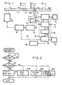
- an optical disc player for use with the CDV 1 comprises an optical pick-up device or head 2 suitably positioned in opposing relation to the read-out surface of the rotatably mounted CDV 1, and being movable in the radial direction of the CDV 1 while the latter is rotated on a turntable or with a spindle by a disc spindle drive motor 10.
- the head 2 is moved in the radially outward direction, as indicated by an arrow AW, for scanning spiral tracks on the rotated CDV 1 so as to pick up or reproduce the signals recorded on such tracks.
- the signals reproduced by the optical pick-up or head 2 are supplied through an RF amplifier 3 to a video signal processing circuit 4 and also to an audio signal processing circuit 6.
- Processed colour video information from the video signal processing circuit 4 is supplied to a monitor or other display device 5 for normally providing a corresponding visual display when the head 2 is scanning tracks in the area V and thereby reproducing colour video signals or information recorded thereon.
- the audio signal processing circuit 6 the signals supplied thereto from the RF amplifier 3 are error-corrected and error-concealed or compensated, and the audio signal is then converted from a digital to an analog signal which is supplied to an audio output terminal 7 to which, for example, a loudspeaker or other audio transducer may be connected.
- the signal from the RF amplifier 3 is further supplied to a clock-synchronising signal separator circuit 8 wherein a clock/synchronising signal is separated from the reproduced signal and is supplied to a disc drive servo circuit 9.
- the servo circuit 9 provides a suitable servo control signal to the disc drive spindle motor 10 by which the rotational speed of the optical disc 1 is determined and maintained.
- an identifying signal is provided in the video signal lead-in area VLI of the optical disc 1 and is coded, as hereinafter described in detail, to identify the TV colour system, for example, one of the PAL, NTSC or SECAM systems, in accordance with which the video signals have been recorded in the following area V.
- the video signal lead-in area VLI is recorded with a standard format independent of the colour TV system used for recording the video signal, for example the standardised audio CD recording format and, therefore, the output of the head 2 when scanning the video signal lead-in area VLI is processed by the audio signal processing circuit 6 which derives the identifying signal therefrom and supplies the same through a decoder 11 to a system controller 12 by which necessary control functions are performed, as hereinafter described in detail.
- the identifying signal is recorded in the video signal lead-in area VLI which employs a standardised recording format independent of the TV system used for recording the video signals in the area V, the identifying signal in the video signal lead-in area VLI will always be reliably reproduced and decoded even though the TV system to which the recorded video signal corresponds may not be the same as that for which the optical disc player is intended.
- the identifying signal is reproduced during scanning of the area VLI in advance of the area V in which the video signals are recorded.
- the decoder 11 can extract the data identifying the TV system used in recording the optical disc from the sub-code of the demodulated, error-corrected and concealed output of the audio signal processing circuit 6. More particularly, the decoder 11 may utilise 8-bit data, as hereinafter described, to identify the recording colour TV system of the disc, and thereby permit suitable control functions or operations to be performed prior to the actual commencement of playback or reproduction of the recorded video signals.
- the system controller 12 executes the following control operations.
- the head 2 is made to traverse the disc 1 in the radially outward direction indicated by the arrow AW in Figure 1 and a step [1] of Figure 2 is repeatedly executed until it is determined that the identifying (ID) signal recorded in the video signal lead-in area VLI has been read into the system controller 12.
- the program proceeds to a step [2] in which it is determined whether or not the colour TV system corresponding to the identifying signal read into the memory of the system controller 12 is consistent with the TV system for which the optical disc player is intended to be used.
- routine or program proceeds to a step [3] in which a flag is set to permit the playback operation of the optical disc player to proceed unimpeded and the control operations represented by the flow chart of Figure 2 are ended.
- the routine may proceed, for example, to a step [4a] in which a disc ejection control signal is supplied from the system controller 12 to a disc ejection device 13 ( Figure 1) by which the optical disc 1 is ejected from the player.
- the routine may proceed also to a step [4b] in which a signal is generated by the system controller 12 for operating a visual or audible alarm or indicator 14 ( Figure 1) by which the user of the optical disc player is alerted that the optical disc in use is not suited for the disc player, or at least not suited for its present operating mode.
- the system controller 12 may respond to such inconsistency by supplying to the monitor or display means 5, a signal causing the monitor 5 to display a message alerting the user of the optical disc player to such inconsistency.
- the displayed message may read "This Player is to be Used for NTSC Discs Only. Don't Play PAL Discs.” The displayed message may be superposed on the normal video display or take the place of the latter.
- the CDV or other optical disc player embodying this invention has an operating mode suitable for use only in connection with optical discs having video signals recorded in accordance with only one predetermined colour TV system.
- the present invention may be embodied in a CDV player selectively capable of different modes of operation for use with CDVs having their video signals recorded in accordance with different colour TV systems, for example, the NTSC and PAL systems.
- the system controller 12 of the optical disc player capable of selective operation as a PAL disc player or as an NTSC disc player provides suitable control signals for changing the operating mode of the disc player, as at a step [4c] in Figure 2.
- Such control signals are supplied through a line 16 to the video signal processing circuit 4, and through a line 17 to the servo circuit 9, so as to effect a change-over operation by which a suitable video signal processing circuit and a rotary disc speed characteristic of a respective operating mode are selected that are proper for the colour TV system with which the CDV or other optical disc has been recorded.
- the above-mentioned colour TV system identifying signal is desirably provided at the sub-code area of the video signal lead-in area VLI of the optical disc 1 recorded according to the CDV format.
- the sub-codes are symbols formed of 8 bits which are recorded for each frame (or block), as shown in Figure 3A.
- sub-coding channels P, Q, R, S, T, U, V and W are provided for 8-bit data. Bits of the sub-coding channels P and Q are utilised to perform the above-mentioned programme functions, that is, to locate the starting points of desired programmes or to achieve the playback of the programmes in a desired order.
- a coding data series is formed by re-arranging data in the channel Q of sub-code data SUB recorded at every frame of digital audio data accompanying a video signal recorded in the video data area V ( Figure 3A).
- a suitable coding method for the sub-code and the audio data is disclosed in detail in US Patent No. US-A-4 541 093 (issued 10 September 1985).
- a track number, an index number, a running time of a music programme in minutes, seconds and frames, an absolute or total running time of the music programme again given in absolute minutes, seconds and frames, and the like are sub-coded according to the predetermined sub-coding method.
- the signal format employed is similar to that referred to as "address (mode) 4" used on optical video discs and on CDVs.
- Figures 3B1 to 3B4 illustrate respective data formats of coded data recorded in the video signal lead-in area VLI and which correspond to the above-described data format shown in Figure 3B.
- "00" represents the number of the track in the "Track No.” area
- a Table of Contents referred to as a "TOC”
- the "Index No.” area is used as a pointer in which is provided a music or video programme number for each music and/or picture programme recorded on the CDV ( Figure 3B1).
- Other frames are provided which have pointers A1, A2 and A0, for example, as shown in Figures 3B2, 3B3 and 3B4, respectively.
- the music number of the first recorded music programme associated with a video programme is provided in the area a of the absolute running time of the frame having the frame pointer A0 ( Figure 3B4).
- the music number of the last music programme associated with a recorded video programme is similarly provided in the area a of the absolute running time of the frame having the pointer A1 ( Figure 3B2).
- the absolute running time up to the end of the last music programme associated with a recorded video programme is provided in the absolute running time area of the frame having the pointer A2 ( Figure 3B3).
- an identifying signal (VID) is provided in the area b , that is, the frame designation, of the absolute running time of the frame having the pointer A0 ( Figure 3B4).
- the undefined area c in each of Figures 3B1 to 3B4 between the indication of the running time of the respective music programme and the indication of the absolute running time may be used to include the data or identifying signal indicating the colour TV system used for recording the respective video signal or programme.
- the TV colour system identifying signal may be provided by utilising, in the "Index No.” area, a numeral larger than A3, that is, a numeral which has not yet been defined in the "Index No.” area. It is also possible to provide the identifying signal for indicating the colour TV system used in recording the video signals by similarly using any available ones of the sub-code channels R to W other than the channels P and Q.
- the present invention is particularly advantageous when applied to a CDV player, it can be applied to any other video disc reproducing apparatus or player for reproducing video discs (such as optical video discs) having video signals recorded in a main track area of the disc and an identifying signal which may be recorded in a lead-in track area which is radially discrete from the main track area and which is scanned in advance of the latter for reproducing the identifying signal and thereby indicating the colour TV system used for recording te video signals.
- video discs such as optical video discs
- the identifying signal in the lead-in track area is reliably detected and reproduced when scanning the lead-in track area even if the optical disc on the player has had its video signals recorded in accordance with a colour TV system that is different from the colour TV system for which the player is intended.
Landscapes
- Engineering & Computer Science (AREA)
- Multimedia (AREA)
- Signal Processing (AREA)
- Optical Recording Or Reproduction (AREA)
- Signal Processing For Digital Recording And Reproducing (AREA)
Claims (9)
- Videoplattenspieler für die Verwendung mit einer Videoplatte (1), die radial getrennte Haupt- und Einlaufspurbereiche (V, VLI) aufweist, in welchen eine Farbvideoinformation entsprechend einem System aus einer Vielzahl von TV- Systemen bzw. Codedaten aufgezeichnet sind, die Daten umfassen, um das eine TV - System zu identifizieren, das beim Aufzeichnen der Farbvideoinformation verwendet wurde, wobei der Videoplattenspieler folgendes umfaßt:
eine Kopfeinrichtung (2) zum anfänglichen Abtasten und Aufzeichnen dieser Codedaten, die in dem Einlaufspurbereich (VLI) aufgezeichnet sind und anschließendem Abtasten und Aufzeichnen der Farbvideoinformation, die in dem Hauptspurbereich (V) aufgezeichnet wurde;
Wiedergabeschaltungseinrichtungen (3 bis 6), die mit der Kopfeinrichtung (2) verbunden sind und wenigstens eine Betriebsart haben, die einem der vorgegebenen TV- Systeme zur Verarbeitung der Farbvideoinformation der Kopfeinrichtung (2) entspricht, wenn das eine TV - System, das für die Aufzeichnung verwendet wurde, verträglich mit einem der vorgegebenen TV - Systeme ist, das der genannten Betriebsart entspricht;
eine Decodiereinrichtung (11) zur Gewinnung der Identifikationsdaten der Kopfeinrichtung (2), wenn letztere einen Einlaufspurbereich (VLI) abtastet, und
eine Steuereinrichtung (12) zum Steuern wenigstens einer Funktion des Videoplattenspielers als Antwort auf eine ermittelte Unvereinbarkeit mit dem vorgegebenen TV- System, das der Betriebsart und dem TV - System entspricht, das zum Aufzeichnen der in Gebrauch befindlichen Videoplatte wie aus den gewonnenen Identifikationsdaten bestimmt verwendet wird. - Plattenspieler nach Anspruch 1, der eine Anzeigeeinrichtung (14) umfaßt, die mit der Steuereinrichtung (12) verbunden ist, wobei die oder eine Funktion, die durch die genannte Unvereinbarkeit gesteuert ist, der Betrieb der Anzeigeeinrichtung (14) ist, um einen Benutzer des Plattenspielers vorzuwarnen, daß die in Gebrauch befindliche Platte (1) nicht für die Betriebsart des Plattenspielers geeignet ist.
- Plattenspieler nach Anspruch 1 oder 2, der eine Anzeigeeinrichtung (5) zum Empfang der verarbeiteten Farbvideoinformation von den Wiedergabeschaltungseinrichtungen (3 bis 6) umfaßt, um dadurch normalerweise eine entsprechende optische Anzeige zu erreichen, und wobei die Steuereinrichtung (12) auf die Unvereinbarkeit antwortet, indem die Anzeigeeinrichtung (5) mit einem Signal beliefert wird, das die Anzeigeeinrichtung veranlasst, eine Mitteilung anzuzeigen, um den Benutzer auf die Unvereinbarkeit vorzuwarnen, wobei die Anzeige der Mitteilung die oder eine Steuerfunktion darstellt.
- Plattenspieler nach Anspruch 1, 2 oder 3, der eine Einrichtung (13) zur Ausgabe der Platte aufweist, um eine Platte (1) aus dem Plattenspieler zu entfernen, und wobei die Steuereinrichtung (12) auf die Unvereinbarkeit durch in Betrieb setzen der Plattenausgabeeinrichtung (13) antwortet, so daß die Ausgabe einer Platte (1) aus dem Plattenspieler, die entsprechend einem TV- System aufgezeichnet wurde, das mit dem vorgegebenen TV- System unvereinbar ist, entsprechend der Betriebsart des Plattenspielers die oder eine Steuerfunktion darstellt.
- Plattenspieler nach einem der vorhergehenden Ansprüche, wobei die Wiedergabeschaltungseinrichtungen (3 bis 6) eine andere Betriebsart entsprechend einem der anderen TV- Systeme haben, und wobei die Wiedergabeschaltungseinrichtungen (3 bis 6) zwischen einer Betriebsart und der anderen Betriebsart zur Verarbeitung der Farbvideoinformation der Kopfeinrichtung (2) schaltbar sind, wenn die Platte (1) mit dem TV- System aufgezeichnet wurde, das der Betriebsart der Wiedergabeschaltungseinrichtungen (3 bis 6) entspricht, und wobei die Steuereinrichtung (12) auf die Unvereinbarkeit durch Umschalten der Wiedergabeschaltungseinrichtungen (3 bis 6) zwischen den Betriebsarten antwortet, um so die Unvereinbarkeit zu beseitigen als die oder eine Steuerfunktion .
- Plattenspieler nach einem der vorhergehenden Ansprüche, wobei die Vielzahl von TV- Systemen wenigstens zwei von den NTSC-, PAL- und SECAM- Systemen umfaßt.
- Plattenspieler nach einem der vorhergehenden Ansprüche, wobei die Farbvideoinformation auf der Platte (1) als frequenzmoduliertes Signal in dem Hauptspurbereich (V) aufgezeichnet ist, wobei der Hauptspurbereich (V) weiterhin ein digitales Audiosignal aufweist, das darin in einem Frequenzband unter dem genannten frequenzmodulierten Signal mit einem Format aufgezeichnet ist, das nicht mit den TV- Systemen variiert, wobei der Einlaufspurbereich (VLI) mit dem Format aufgezeichnet wird, welches Subcode- Kanäle umfaßt, von denen wenigstens einer die Daten enthält, um das TV- System, das zum Aufzeichnen der Farbvideoinformation verwendet wird, zu identifizieren, wobei die Wiedergabeschaltungseinrichtungen (3 bis 6) eine Videosignalverarbeitungseinrichtung (4) zur Demodulation des frequenzmodulierten Signals umfaßt und dadurch daraus die Farbvideoinformation gewinnt, und eine Audioverarbeitungseinrichtung (6) zur Gewinnung des Audiosignals von der Kopfeinrichtung (2), wenn der Hauptspurbereich (V) abgetastet wird, sowie zur Gewinnung der Codedaten in den Subcode- Kanälen der Kopfeinrichtung (2), wenn der Einlaufspurbereich (VLI) abgetastet wird, und wobei die Einrichtung (11) zur Decodierung fähig ist, die Daten vorzusehen, um das TV- System, das zum Aufzeichnen der Farbvideoinformation verwendet wird, aus den Codedaten zu identifizieren, die durch die audioverarbeitende Einrichtung (6) gewonnen werden.
- Plattenspieler nach einem der vorhergehenden Ansprüche, zum Gebrauch mit einer optischen Platte (1), wobei die Kopfeinrichtung einen optischen Kopf (2) umfaßt.
- Plattenspieler nach Anspruch 8, wobei die optische Platte eine CDV (1) ist, die einen Audiospurbereich (A) aufweist, in welchem nur digitale Audiosignale mit demselben Format wie beim Einlaufspurbereich (VLI) aufgezeichnet sind, und wobei der Einlaufspurbereich (VLI) radial zwischen dem Audiospurbereich (A) und dem Hauptspurbereich (V) angeordnet ist, und wobei die Kopfeinrichtung (2) normalerweise in der Lage ist, die CDV (1) in der radialen Richtung vom Audiospurbereich (A) zum Hauptspurbereich abzutasten.
Applications Claiming Priority (2)
| Application Number | Priority Date | Filing Date | Title |
|---|---|---|---|
| JP188582/87 | 1987-07-28 | ||
| JP62188582A JP2638815B2 (ja) | 1987-07-28 | 1987-07-28 | ディスク再生装置 |
Publications (2)
| Publication Number | Publication Date |
|---|---|
| EP0301809A1 EP0301809A1 (de) | 1989-02-01 |
| EP0301809B1 true EP0301809B1 (de) | 1992-09-09 |
Family
ID=16226197
Family Applications (1)
| Application Number | Title | Priority Date | Filing Date |
|---|---|---|---|
| EP88306875A Expired EP0301809B1 (de) | 1987-07-28 | 1988-07-26 | Videoplattenspieler |
Country Status (5)
| Country | Link |
|---|---|
| US (1) | US4914523A (de) |
| EP (1) | EP0301809B1 (de) |
| JP (1) | JP2638815B2 (de) |
| DE (1) | DE3874456T2 (de) |
| HK (1) | HK96395A (de) |
Families Citing this family (34)
| Publication number | Priority date | Publication date | Assignee | Title |
|---|---|---|---|---|
| JPH02198266A (ja) * | 1989-01-27 | 1990-08-06 | Toshiba Corp | 画像形成装置 |
| JP2906462B2 (ja) * | 1989-07-18 | 1999-06-21 | ソニー株式会社 | テレビジョン受信機 |
| JP2771266B2 (ja) * | 1989-07-28 | 1998-07-02 | 株式会社日立製作所 | 多方式の映像信号の再生表示装置 |
| JP2545628B2 (ja) * | 1990-02-23 | 1996-10-23 | 三菱電機株式会社 | 磁気再生方式 |
| JP2507174B2 (ja) * | 1990-11-20 | 1996-06-12 | 松下電器産業株式会社 | 光ディスク装置 |
| US5428456A (en) * | 1991-03-15 | 1995-06-27 | Eastman Kodak Company | Method and apparatus for adaptively reducing interline flicker of TV-displayed image |
| JP2640052B2 (ja) * | 1991-06-03 | 1997-08-13 | 三洋電機株式会社 | 誤装着報知システム及び画像展示システム |
| US5469218A (en) * | 1991-07-23 | 1995-11-21 | Canon Kabushiki Kaisha | Image signal processing device with conversion of sample frequency of digital color-difference data signals |
| JPH0594665A (ja) * | 1991-09-30 | 1993-04-16 | Sony Corp | デイスクプレイヤ |
| JPH0612788A (ja) * | 1992-06-29 | 1994-01-21 | Canon Inc | 記録/再生方法 |
| US5432801A (en) * | 1993-07-23 | 1995-07-11 | Commodore Electronics Limited | Method and apparatus for performing multiple simultaneous error detection on data having unknown format |
| US5764846A (en) * | 1993-10-29 | 1998-06-09 | Kabushiki Kaisha Toshiba | Multi-scene recording medium and apparatus for reproducing data therefrom |
| US5850500A (en) * | 1995-06-28 | 1998-12-15 | Kabushiki Kaisha Toshiba | Recording medium comprising a plurality of different languages which are selectable independently of each other |
| US5652824A (en) * | 1993-10-29 | 1997-07-29 | Tokyo Shibaura Electric Co | Multilingual recording medium and reproducing apparatus with automatic selection of substitutes and languages based on frequency of selections |
| EP0836192A1 (de) * | 1993-10-29 | 1998-04-15 | Kabushiki Kaisha Toshiba | Aufzeichnungsmedium für Mehrfachszenen, und Verfahren und Vorrichtung zur Wiedergabe von Daten davon |
| KR0164776B1 (ko) * | 1993-10-30 | 1999-03-20 | 김광호 | 레이저 디스크 플레이어 시스템의 엔티에스시/팔신호 검출회로 |
| JPH07298160A (ja) * | 1994-04-25 | 1995-11-10 | Hitachi Ltd | ビデオcd再生装置内蔵テレビジョン装置 |
| TW250565B (en) * | 1994-10-20 | 1995-07-01 | Digital Audio Disc Corp | Mass production of multisession discs |
| US5778142A (en) * | 1994-11-24 | 1998-07-07 | Kabushiki Kaisha Toshiba | Large capacity recording medium, method and apparatus for reproducing data from a large-capacity recording medium, and method and apparatus for recording data on a large-capacity recording medium |
| CA2168327C (en) * | 1995-01-30 | 2000-04-11 | Shinichi Kikuchi | A recording medium on which a data containing navigation data is recorded, a method and apparatus for reproducing a data according to navigationdata, a method and apparatus for recording a data containing navigation data on a recording medium. |
| EP0737975B1 (de) * | 1995-04-11 | 1999-07-07 | Kabushiki Kaisha Toshiba | Aufzeichnungdmedium, -gerät und -methode zur Aufzeichnung von Daten auf einem Aufzeichnungsmedium, und Wiedergabegerät und -methode zur Wiedergabe von Daten von einem Aufzeichnungsmedium |
| US6009433A (en) * | 1995-04-14 | 1999-12-28 | Kabushiki Kaisha Toshiba | Information storage and information transmission media with parental control |
| US5813010A (en) * | 1995-04-14 | 1998-09-22 | Kabushiki Kaisha Toshiba | Information storage and information transmission media with parental control |
| US5838874A (en) * | 1995-05-08 | 1998-11-17 | Kabushiki Kaisha Toshiba | Audiovisual encoding system with a reduced number of audio encoders |
| US5784519A (en) * | 1995-06-15 | 1998-07-21 | Kabushiki Kaisha Toshiba | Multi-scene recording medium and apparatus for reproducing data therefrom |
| GB9603332D0 (en) | 1996-02-14 | 1996-04-17 | Thomson Consumer Electronics | Interface for digital recorder and display |
| CN1200858A (zh) * | 1995-09-15 | 1998-12-02 | 汤姆森消费电子有限公司 | 简化的视频信号输入选择器 |
| US6363213B1 (en) * | 1996-02-14 | 2002-03-26 | Thomson Licensing S.A. | Interface for digital recorder and display |
| CN1260970C (zh) * | 1996-05-09 | 2006-06-21 | 松下电器产业株式会社 | 用于多媒体光盘的记录方法、再生装置及再生方法 |
| KR100417416B1 (ko) * | 1997-05-29 | 2004-05-22 | 엘지전자 주식회사 | 광디스크의타이틀이동에따른에러정정방법 |
| JP3376265B2 (ja) | 1997-12-25 | 2003-02-10 | 株式会社東芝 | 複数コンテンツのオブジェクト共有化システム |
| US6966023B2 (en) * | 2002-02-21 | 2005-11-15 | Mediatek Incorporation | Encoding method for an optical recorder |
| AU2003201837A1 (en) * | 2002-04-01 | 2003-10-23 | Sony Corporation | Storage medium and storage medium recording method |
| KR100554791B1 (ko) | 2003-01-24 | 2006-02-22 | 엘지전자 주식회사 | 튜너가 구비된 광디스크 장치에서의 재생 비디오 신호처리방식 설정방법 |
Family Cites Families (12)
| Publication number | Priority date | Publication date | Assignee | Title |
|---|---|---|---|---|
| GB2002990B (en) * | 1977-06-24 | 1982-01-27 | Rca Corp | Dual standard video record player |
| US4204220A (en) * | 1977-06-24 | 1980-05-20 | Rca Corporation | Dual standard video disc player |
| US4282545A (en) * | 1978-06-08 | 1981-08-04 | Blaupunkt-Werke Gmbh | Method and apparatus for playing back color video records through television receiver operating at a different color standard |
| CA1145464A (en) * | 1979-08-22 | 1983-04-26 | Wayne R. Dakin | Programmed video record disc and related playback apparatus |
| JPS56158581A (en) * | 1980-05-10 | 1981-12-07 | Victor Co Of Japan Ltd | Recording and playback system for rotating recording medium |
| JPS5737777A (en) * | 1980-08-19 | 1982-03-02 | Victor Co Of Japan Ltd | Reproducing device for rotary information recording medium |
| US4490810A (en) * | 1982-02-16 | 1984-12-25 | Hon David C | Automated instruction, game and data retrieval system |
| US4535366A (en) * | 1982-02-22 | 1985-08-13 | Discovision Associates | Universal video data playback |
| JPS59140666A (ja) * | 1983-01-31 | 1984-08-13 | Victor Co Of Japan Ltd | 回転記録媒体再生装置 |
| FR2541062B1 (fr) * | 1983-02-15 | 1987-01-02 | Thomson Brandt | Systeme conversationnel comportant un dispositif de visualisation, un ordinateur et une source d'informations videofrequence pre-enregistrees |
| US4777537A (en) * | 1985-10-21 | 1988-10-11 | Sony Corporation | Signal recording apparatus and method |
| JPH0714222B2 (ja) * | 1986-04-15 | 1995-02-15 | パイオニア株式会社 | ディスク記録情報再生装置 |
-
1987
- 1987-07-28 JP JP62188582A patent/JP2638815B2/ja not_active Expired - Lifetime
-
1988
- 1988-07-19 US US07/221,048 patent/US4914523A/en not_active Expired - Lifetime
- 1988-07-26 EP EP88306875A patent/EP0301809B1/de not_active Expired
- 1988-07-26 DE DE8888306875T patent/DE3874456T2/de not_active Expired - Lifetime
-
1995
- 1995-06-15 HK HK96395A patent/HK96395A/en not_active IP Right Cessation
Also Published As
| Publication number | Publication date |
|---|---|
| EP0301809A1 (de) | 1989-02-01 |
| US4914523A (en) | 1990-04-03 |
| DE3874456D1 (de) | 1992-10-15 |
| DE3874456T2 (de) | 1993-03-25 |
| JPS6432589A (en) | 1989-02-02 |
| JP2638815B2 (ja) | 1997-08-06 |
| HK96395A (en) | 1995-06-23 |
Similar Documents
| Publication | Publication Date | Title |
|---|---|---|
| EP0301809B1 (de) | Videoplattenspieler | |
| EP0165320B1 (de) | Plattenförmiges speichermedium und vorrichtung zur wiedergabe | |
| US5530686A (en) | Record carrier having a track including audio information and additional non-audio information, and apparatus for reading and/or reproducing certain of the information included in such a track | |
| JP3779127B2 (ja) | 情報キャリア | |
| US6038366A (en) | Magnetic recording/reproducing apparatus for search programs recorded on magnetic tape | |
| US5150113A (en) | Method and apparatus for transmitting an information signal together with data packets of related and unrelated textual information and receiving apparatus therefor | |
| US5862107A (en) | Disc player capable of automatically interchanging a plurality of loaded discs | |
| JP3897833B2 (ja) | 情報記録装置及び情報再生装置 | |
| US4970602A (en) | Disk player for displaying recorded audio signals | |
| EP0491563B1 (de) | Informations-Aufnahme/Wiedergabegerät | |
| EP1128384A2 (de) | Plattenwiedergabegerät | |
| US5410524A (en) | Recording medium apparatus for inhibiting playback of predetermined recorded portions | |
| US6970638B1 (en) | Recording medium reproducing apparatus | |
| US5703994A (en) | Index processor for digital VCR and method therefor | |
| JP3067664B2 (ja) | ディスク再生装置 | |
| EP1679707B1 (de) | Verfahren zur Wiedergabe von Dokumenten mit Sequenzstörungen und entsprechende Wiedergabevorrichtung | |
| JPH0322279A (ja) | 情報信号記録媒体及びその演奏装置 | |
| JP3090895B2 (ja) | 記録媒体再生装置 | |
| KR0129026B1 (ko) | Cdg 플레이어와 vcr 복합제품의 기능표시 제어방법 | |
| KR970011829B1 (ko) | 광디스크플레이어와 vcr(video cassette recorder)의 복합제품에서의 비스자동삽입장치 | |
| KR100203859B1 (ko) | 비디오 컴팩트디스크의 콘트롤신호 검출방법 | |
| KR100189920B1 (ko) | 광 디스크 재생 정보 표시 방법 | |
| JPS63282960A (ja) | 再生装置 | |
| JP2000173176A (ja) | Dvdプレーヤ | |
| JPH10116483A (ja) | 光ディスク装置及び光ディスク |
Legal Events
| Date | Code | Title | Description |
|---|---|---|---|
| PUAI | Public reference made under article 153(3) epc to a published international application that has entered the european phase |
Free format text: ORIGINAL CODE: 0009012 |
|
| 17P | Request for examination filed |
Effective date: 19880812 |
|
| AK | Designated contracting states |
Kind code of ref document: A1 Designated state(s): DE GB NL |
|
| 17Q | First examination report despatched |
Effective date: 19911204 |
|
| GRAA | (expected) grant |
Free format text: ORIGINAL CODE: 0009210 |
|
| AK | Designated contracting states |
Kind code of ref document: B1 Designated state(s): DE GB NL |
|
| REF | Corresponds to: |
Ref document number: 3874456 Country of ref document: DE Date of ref document: 19921015 |
|
| PLBE | No opposition filed within time limit |
Free format text: ORIGINAL CODE: 0009261 |
|
| STAA | Information on the status of an ep patent application or granted ep patent |
Free format text: STATUS: NO OPPOSITION FILED WITHIN TIME LIMIT |
|
| 26N | No opposition filed | ||
| REG | Reference to a national code |
Ref country code: GB Ref legal event code: IF02 |
|
| PGFP | Annual fee paid to national office [announced via postgrant information from national office to epo] |
Ref country code: DE Payment date: 20070719 Year of fee payment: 20 |
|
| PGFP | Annual fee paid to national office [announced via postgrant information from national office to epo] |
Ref country code: GB Payment date: 20070725 Year of fee payment: 20 |
|
| PGFP | Annual fee paid to national office [announced via postgrant information from national office to epo] |
Ref country code: NL Payment date: 20070624 Year of fee payment: 20 |
|
| REG | Reference to a national code |
Ref country code: GB Ref legal event code: PE20 Expiry date: 20080725 |
|
| NLV7 | Nl: ceased due to reaching the maximum lifetime of a patent |
Effective date: 20080726 |
|
| PG25 | Lapsed in a contracting state [announced via postgrant information from national office to epo] |
Ref country code: NL Free format text: LAPSE BECAUSE OF EXPIRATION OF PROTECTION Effective date: 20080726 |
|
| PG25 | Lapsed in a contracting state [announced via postgrant information from national office to epo] |
Ref country code: GB Free format text: LAPSE BECAUSE OF EXPIRATION OF PROTECTION Effective date: 20080725 |