EP0301845A1 - Abtastvorrichtung - Google Patents
Abtastvorrichtung Download PDFInfo
- Publication number
- EP0301845A1 EP0301845A1 EP19880306940 EP88306940A EP0301845A1 EP 0301845 A1 EP0301845 A1 EP 0301845A1 EP 19880306940 EP19880306940 EP 19880306940 EP 88306940 A EP88306940 A EP 88306940A EP 0301845 A1 EP0301845 A1 EP 0301845A1
- Authority
- EP
- European Patent Office
- Prior art keywords
- piston
- magnetic
- seals
- cylinder
- magnetic material
- Prior art date
- Legal status (The legal status is an assumption and is not a legal conclusion. Google has not performed a legal analysis and makes no representation as to the accuracy of the status listed.)
- Granted
Links
- 239000000696 magnetic material Substances 0.000 claims abstract description 16
- 230000005291 magnetic effect Effects 0.000 claims description 9
- 239000000463 material Substances 0.000 claims description 9
- 229910000859 α-Fe Inorganic materials 0.000 claims description 7
- 239000006249 magnetic particle Substances 0.000 claims description 4
- 239000004033 plastic Substances 0.000 claims description 4
- 229920003023 plastic Polymers 0.000 claims description 4
- 229910052712 strontium Inorganic materials 0.000 claims description 4
- CIOAGBVUUVVLOB-UHFFFAOYSA-N strontium atom Chemical compound [Sr] CIOAGBVUUVVLOB-UHFFFAOYSA-N 0.000 claims description 4
- 239000004677 Nylon Substances 0.000 claims description 3
- 229920001778 nylon Polymers 0.000 claims description 3
- 239000000919 ceramic Substances 0.000 claims description 2
- KPLQYGBQNPPQGA-UHFFFAOYSA-N cobalt samarium Chemical compound [Co].[Sm] KPLQYGBQNPPQGA-UHFFFAOYSA-N 0.000 claims description 2
- 239000003302 ferromagnetic material Substances 0.000 claims description 2
- 238000001746 injection moulding Methods 0.000 claims description 2
- 239000011159 matrix material Substances 0.000 claims description 2
- 229910000938 samarium–cobalt magnet Inorganic materials 0.000 claims description 2
- 238000002347 injection Methods 0.000 description 4
- 239000007924 injection Substances 0.000 description 4
- 239000000945 filler Substances 0.000 description 2
- BGPVFRJUHWVFKM-UHFFFAOYSA-N N1=C2C=CC=CC2=[N+]([O-])C1(CC1)CCC21N=C1C=CC=CC1=[N+]2[O-] Chemical compound N1=C2C=CC=CC2=[N+]([O-])C1(CC1)CCC21N=C1C=CC=CC1=[N+]2[O-] BGPVFRJUHWVFKM-UHFFFAOYSA-N 0.000 description 1
- 235000014676 Phragmites communis Nutrition 0.000 description 1
- YWJUZWOHLHBWQY-UHFFFAOYSA-N decanedioic acid;hexane-1,6-diamine Chemical compound NCCCCCCN.OC(=O)CCCCCCCCC(O)=O YWJUZWOHLHBWQY-UHFFFAOYSA-N 0.000 description 1
- 230000001419 dependent effect Effects 0.000 description 1
- 239000002991 molded plastic Substances 0.000 description 1
Images
Classifications
-
- F—MECHANICAL ENGINEERING; LIGHTING; HEATING; WEAPONS; BLASTING
- F15—FLUID-PRESSURE ACTUATORS; HYDRAULICS OR PNEUMATICS IN GENERAL
- F15B—SYSTEMS ACTING BY MEANS OF FLUIDS IN GENERAL; FLUID-PRESSURE ACTUATORS, e.g. SERVOMOTORS; DETAILS OF FLUID-PRESSURE SYSTEMS, NOT OTHERWISE PROVIDED FOR
- F15B15/00—Fluid-actuated devices for displacing a member from one position to another; Gearing associated therewith
- F15B15/20—Other details, e.g. assembly with regulating devices
- F15B15/28—Means for indicating the position, e.g. end of stroke
- F15B15/2807—Position switches, i.e. means for sensing of discrete positions only, e.g. limit switches
Definitions
- This invention relates to non-contact positional sensing systems and has particular reference to non-contact positional sensing systems for a piston movable longitudinally within a cylinder.
- Non-contact positional sensing of pneumatic cylinder pistons is common practice. Normally, a magnet is fitted to the piston and a reed switch or magnetically sensitive proximity sensors are attached to the cylinder barrel around its diameter.
- the magnets which have been used heretofor have been of the ring type in various materials dependent upon the required field strength. Typical examples have been Samarium Cobalt, Ceramic Ferrite or a plastics material with a ferrite filler.
- the magnetic ring may be located between split piston halves.
- a non-contact positional sensing system for a piston movable longitudinally within a cylinder in which the cylinder is formed of non-ferromagnetic material, there is a magnetically sensitive proximity sensor on the outside of the cylinder and the piston is magnetic, characterised in that the piston is formed substantially entirely from magnetic material.
- the piston may be moulded from magnetic material.
- the magnetic material may comprise magnetic particles in a non-magnetic matrix.
- the piston may be moulded by injection moulding.
- the proportion of magnetic particles is preferably as high as practical and may be in the range 60-90% or 70-90% or 80-90% of the material.
- the plastics material may be nylon and is preferably nylon 6/10.
- the magnetic material may be a strontium ferrite filler. There may be present 88% by weight of strontium ferrite material.
- the piston may be provided with non-magnetic seals which may be of conventional form.
- the seals may be cup seals or 'O' ring seals or disc seals.
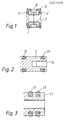
- a piston comprising a pair of moulded plastics halves 1, 2 which are conjoined together by an inner sleeve 3.
- the two halves 1 and 2 trap between them a ring magnet 4.
- the pair of seals 5, 6 seal the piston within a cylinder.
- the cylinder and proximity sensors are well known and conventional and are not described herein.
- the magnetic piston comprises an injection moulded body 7 formed of 6/10 nylon containing 88% by weight of strontium ferrite.
- the piston has a blind bore 8 permitting it to be attached to a piston rod, further piston or other piston follower.
- Cup seals 9 and 10 seal the piston within the cylinder.
- the piston may be a hollow piston as shown in Figure 3 in which the piston 11 is in the form of an injection moulded tubular member having cup seals 12 and 13.
- the piston is formed almost entirely of magnetic material, significant savings in the length of the piston can be achieved by using a moulded form of magnetic material.
Landscapes
- Engineering & Computer Science (AREA)
- Physics & Mathematics (AREA)
- Fluid Mechanics (AREA)
- Mechanical Engineering (AREA)
- General Engineering & Computer Science (AREA)
- Measurement Of Length, Angles, Or The Like Using Electric Or Magnetic Means (AREA)
- Pistons, Piston Rings, And Cylinders (AREA)
Applications Claiming Priority (2)
| Application Number | Priority Date | Filing Date | Title |
|---|---|---|---|
| GB878718173A GB8718173D0 (en) | 1987-07-31 | 1987-07-31 | Sensing system |
| GB8718173 | 1987-07-31 |
Publications (2)
| Publication Number | Publication Date |
|---|---|
| EP0301845A1 true EP0301845A1 (de) | 1989-02-01 |
| EP0301845B1 EP0301845B1 (de) | 1990-12-05 |
Family
ID=10621614
Family Applications (1)
| Application Number | Title | Priority Date | Filing Date |
|---|---|---|---|
| EP19880306940 Expired EP0301845B1 (de) | 1987-07-31 | 1988-07-28 | Abtastvorrichtung |
Country Status (3)
| Country | Link |
|---|---|
| EP (1) | EP0301845B1 (de) |
| DE (1) | DE3861224D1 (de) |
| GB (1) | GB8718173D0 (de) |
Cited By (3)
| Publication number | Priority date | Publication date | Assignee | Title |
|---|---|---|---|---|
| EP0838616A3 (de) * | 1996-10-28 | 1998-05-13 | Hygrama Ag | Kolben für einen pneumatischen oder hydraulischen Arbeitszylinder |
| EP1818545A1 (de) * | 2006-02-14 | 2007-08-15 | Parker Hannifin GmbH & Co. KG Geschäftsbereich Dichtungen | Magnetkolben für Pneumatikzylinder |
| WO2008003648A3 (de) * | 2006-07-05 | 2008-02-28 | Zahnradfabrik Friedrichshafen | Einrichtung zur sensierung der position, drehzahl und/oder drehwinkels eines kolbens |
Citations (1)
| Publication number | Priority date | Publication date | Assignee | Title |
|---|---|---|---|---|
| DE3424461A1 (de) * | 1983-07-05 | 1985-01-24 | Kabushiki Kaisha Tokyo Koki Seizosho, Tokio/Tokyo | Betaetigungsvorrichtung |
-
1987
- 1987-07-31 GB GB878718173A patent/GB8718173D0/en active Pending
-
1988
- 1988-07-28 DE DE8888306940T patent/DE3861224D1/de not_active Expired - Lifetime
- 1988-07-28 EP EP19880306940 patent/EP0301845B1/de not_active Expired
Patent Citations (1)
| Publication number | Priority date | Publication date | Assignee | Title |
|---|---|---|---|---|
| DE3424461A1 (de) * | 1983-07-05 | 1985-01-24 | Kabushiki Kaisha Tokyo Koki Seizosho, Tokio/Tokyo | Betaetigungsvorrichtung |
Cited By (3)
| Publication number | Priority date | Publication date | Assignee | Title |
|---|---|---|---|---|
| EP0838616A3 (de) * | 1996-10-28 | 1998-05-13 | Hygrama Ag | Kolben für einen pneumatischen oder hydraulischen Arbeitszylinder |
| EP1818545A1 (de) * | 2006-02-14 | 2007-08-15 | Parker Hannifin GmbH & Co. KG Geschäftsbereich Dichtungen | Magnetkolben für Pneumatikzylinder |
| WO2008003648A3 (de) * | 2006-07-05 | 2008-02-28 | Zahnradfabrik Friedrichshafen | Einrichtung zur sensierung der position, drehzahl und/oder drehwinkels eines kolbens |
Also Published As
| Publication number | Publication date |
|---|---|
| GB8718173D0 (en) | 1987-09-09 |
| EP0301845B1 (de) | 1990-12-05 |
| DE3861224D1 (de) | 1991-01-17 |
Similar Documents
| Publication | Publication Date | Title |
|---|---|---|
| US20040227509A1 (en) | Position detector for a moving part in a pipe | |
| JP3395402B2 (ja) | 移動量検出器 | |
| US20080231261A1 (en) | Hall-type sensor for measuring linear movements | |
| US5045785A (en) | Linear position sensor with movable tapered element | |
| CN1828067B (zh) | 带位置检测机构的促动器 | |
| CN101532521B (zh) | 具有信息发送器的液压缸 | |
| KR20030084639A (ko) | 위치 감지 장치 | |
| US5266917A (en) | Linear magnetic sensing device | |
| SE465683B (sv) | Kolvcylinderaggregat | |
| DE3865636D1 (de) | Infusionsspritzenpumpe. | |
| JPH02116719A (ja) | 磁気センサ | |
| US20060113990A1 (en) | Linear position sensor | |
| EP1217220A3 (de) | Fluidzylinder mit integriertem Positionsensor | |
| JP2002538450A (ja) | 磁気感受性プローブ位置センサ | |
| WO1987006656A1 (en) | Hydraulic cylinder with piston and with a magnetic device for piston position determination | |
| JPH03130615A (ja) | 高分解能符号器 | |
| ATE89098T1 (de) | Elektromagnet mit einem tauchanker. | |
| EP0301845B1 (de) | Abtastvorrichtung | |
| DE59913943D1 (de) | Kunststoffgebundener Ringmagnet | |
| EP1335127A3 (de) | Elektromagnetisches Kraftstoffeinspritzventil | |
| ATE223002T1 (de) | Druckmittelbetätigte zylinder-kolben-anordnung mit einem magnetfeldsensor | |
| GB2164154A (en) | Magnetic velocity sensor | |
| US20040066187A1 (en) | Scale and method for producing this scale and position measuring system employing such a scale | |
| DE3780001D1 (de) | Potentiometer bzw. veraenderbarer widerstand. | |
| US20030048100A1 (en) | Magnetic sensor of the position of a moving member over a trajectory followed by the moving member |
Legal Events
| Date | Code | Title | Description |
|---|---|---|---|
| PUAI | Public reference made under article 153(3) epc to a published international application that has entered the european phase |
Free format text: ORIGINAL CODE: 0009012 |
|
| AK | Designated contracting states |
Kind code of ref document: A1 Designated state(s): DE FR GB IT |
|
| 17P | Request for examination filed |
Effective date: 19890804 |
|
| 17Q | First examination report despatched |
Effective date: 19891106 |
|
| GRAA | (expected) grant |
Free format text: ORIGINAL CODE: 0009210 |
|
| AK | Designated contracting states |
Kind code of ref document: B1 Designated state(s): DE FR GB IT |
|
| ITF | It: translation for a ep patent filed | ||
| REF | Corresponds to: |
Ref document number: 3861224 Country of ref document: DE Date of ref document: 19910117 |
|
| ET | Fr: translation filed | ||
| PLBE | No opposition filed within time limit |
Free format text: ORIGINAL CODE: 0009261 |
|
| STAA | Information on the status of an ep patent application or granted ep patent |
Free format text: STATUS: NO OPPOSITION FILED WITHIN TIME LIMIT |
|
| 26N | No opposition filed | ||
| ITTA | It: last paid annual fee | ||
| PGFP | Annual fee paid to national office [announced via postgrant information from national office to epo] |
Ref country code: FR Payment date: 19980611 Year of fee payment: 11 |
|
| PG25 | Lapsed in a contracting state [announced via postgrant information from national office to epo] |
Ref country code: FR Free format text: THE PATENT HAS BEEN ANNULLED BY A DECISION OF A NATIONAL AUTHORITY Effective date: 19990731 |
|
| REG | Reference to a national code |
Ref country code: FR Ref legal event code: ST |
|
| REG | Reference to a national code |
Ref country code: GB Ref legal event code: IF02 |
|
| PG25 | Lapsed in a contracting state [announced via postgrant information from national office to epo] |
Ref country code: IT Free format text: LAPSE BECAUSE OF NON-PAYMENT OF DUE FEES Effective date: 20050728 |
|
| PGFP | Annual fee paid to national office [announced via postgrant information from national office to epo] |
Ref country code: DE Payment date: 20070726 Year of fee payment: 20 |
|
| PGFP | Annual fee paid to national office [announced via postgrant information from national office to epo] |
Ref country code: GB Payment date: 20070725 Year of fee payment: 20 |
|
| REG | Reference to a national code |
Ref country code: GB Ref legal event code: PE20 Expiry date: 20080727 |
|
| PG25 | Lapsed in a contracting state [announced via postgrant information from national office to epo] |
Ref country code: GB Free format text: LAPSE BECAUSE OF EXPIRATION OF PROTECTION Effective date: 20080727 |