EP0302157A1 - Procédé de fabrication de récipients tubulaires - Google Patents
Procédé de fabrication de récipients tubulaires Download PDFInfo
- Publication number
- EP0302157A1 EP0302157A1 EP87730088A EP87730088A EP0302157A1 EP 0302157 A1 EP0302157 A1 EP 0302157A1 EP 87730088 A EP87730088 A EP 87730088A EP 87730088 A EP87730088 A EP 87730088A EP 0302157 A1 EP0302157 A1 EP 0302157A1
- Authority
- EP
- European Patent Office
- Prior art keywords
- tube
- container
- base part
- ring
- pipe
- Prior art date
- Legal status (The legal status is an assumption and is not a legal conclusion. Google has not performed a legal analysis and makes no representation as to the accuracy of the status listed.)
- Granted
Links
- 238000004519 manufacturing process Methods 0.000 title claims description 15
- 238000000034 method Methods 0.000 claims abstract description 12
- 229910052751 metal Inorganic materials 0.000 claims abstract description 7
- 239000002184 metal Substances 0.000 claims abstract description 7
- 238000003780 insertion Methods 0.000 claims abstract 2
- 230000037431 insertion Effects 0.000 claims abstract 2
- 239000006096 absorbing agent Substances 0.000 claims description 4
- 230000035939 shock Effects 0.000 claims description 4
- 230000007797 corrosion Effects 0.000 claims description 3
- 238000005260 corrosion Methods 0.000 claims description 3
- 239000000463 material Substances 0.000 claims description 3
- 238000009987 spinning Methods 0.000 claims description 3
- 229910000831 Steel Inorganic materials 0.000 claims description 2
- 239000010959 steel Substances 0.000 claims description 2
- 238000003825 pressing Methods 0.000 claims 2
- 238000005246 galvanizing Methods 0.000 claims 1
- 238000002844 melting Methods 0.000 claims 1
- 230000008018 melting Effects 0.000 claims 1
- 238000010438 heat treatment Methods 0.000 description 3
- 238000005096 rolling process Methods 0.000 description 3
- ATUOYWHBWRKTHZ-UHFFFAOYSA-N Propane Chemical compound CCC ATUOYWHBWRKTHZ-UHFFFAOYSA-N 0.000 description 2
- VGGSQFUCUMXWEO-UHFFFAOYSA-N Ethene Chemical compound C=C VGGSQFUCUMXWEO-UHFFFAOYSA-N 0.000 description 1
- 239000005977 Ethylene Substances 0.000 description 1
- ATJFFYVFTNAWJD-UHFFFAOYSA-N Tin Chemical compound [Sn] ATJFFYVFTNAWJD-UHFFFAOYSA-N 0.000 description 1
- HCHKCACWOHOZIP-UHFFFAOYSA-N Zinc Chemical compound [Zn] HCHKCACWOHOZIP-UHFFFAOYSA-N 0.000 description 1
- 239000000853 adhesive Substances 0.000 description 1
- 230000001070 adhesive effect Effects 0.000 description 1
- 229910052782 aluminium Inorganic materials 0.000 description 1
- XAGFODPZIPBFFR-UHFFFAOYSA-N aluminium Chemical compound [Al] XAGFODPZIPBFFR-UHFFFAOYSA-N 0.000 description 1
- 239000003795 chemical substances by application Substances 0.000 description 1
- 238000004040 coloring Methods 0.000 description 1
- 230000006378 damage Effects 0.000 description 1
- 239000003292 glue Substances 0.000 description 1
- 238000009434 installation Methods 0.000 description 1
- 150000002739 metals Chemical class 0.000 description 1
- 239000001294 propane Substances 0.000 description 1
- 229910000679 solder Inorganic materials 0.000 description 1
- 238000005476 soldering Methods 0.000 description 1
- 238000005496 tempering Methods 0.000 description 1
- 229910052718 tin Inorganic materials 0.000 description 1
- 229910052725 zinc Inorganic materials 0.000 description 1
- 239000011701 zinc Substances 0.000 description 1
Images
Classifications
-
- B—PERFORMING OPERATIONS; TRANSPORTING
- B21—MECHANICAL METAL-WORKING WITHOUT ESSENTIALLY REMOVING MATERIAL; PUNCHING METAL
- B21D—WORKING OR PROCESSING OF SHEET METAL OR METAL TUBES, RODS OR PROFILES WITHOUT ESSENTIALLY REMOVING MATERIAL; PUNCHING METAL
- B21D51/00—Making hollow objects
- B21D51/16—Making hollow objects characterised by the use of the objects
- B21D51/24—Making hollow objects characterised by the use of the objects high-pressure containers, e.g. boilers, bottles
Definitions
- the invention relates to a method for producing a tube container according to the preamble of the main claim.
- the invention has for its object to simplify the known manufacturing process and technologically improve the products.
- the object is achieved by the invention with the characterizing features of the main claim.
- the measures according to the subclaims to the method result in additional advantages.
- the invention includes the special use of the container pipes produced in this way as compressed gas cylinders, shock absorber container pipes or heat-insulated container pipes.
- the great advantage of the invention is that the pipe section is positively connected to the bottom part. This creates a mechanically firm connection.
- Another advantage is that the annular insert creates a gas-tight connection.
- the pressure rollers which are easy to handle, are carried out at room temperature, which further simplifies production and above it also allows the use of heat-treated high-strength steel pipes. For example, pipes made of thermomechanically rolled sheet metal with a yield strength of over 600 N / mm2 can be used, which means that shock absorber containers can be made thin-walled to save weight.
- the measure according to claim 2 is mainly suitable.
- the pressure roll causes the destruction of a ring filled with adhesive.
- the positive connection between the pipe end and the base part by the spinning roll is also generated in this case.
- the basic idea of connecting the pipe end to the base part by spinning rollers can also be carried out with a soft, plastically deformable metal ring.
- This alternative can be further developed in that the deformable metal enters into a solder connection with the material of the tube and the base part and the tube container produced by pressure rollers is briefly heated to the soldering temperature at the end.
- the heating can also be connected to the production of a metallic corrosion protection layer on the roll container.
- the metals aluminum, zinc, tin may be provided with an intermediate layer.
- the manufacturing processes are of great importance for the production of compressed gas bottles, for example ethylene bottles, propane gas bottles, bottles for extinguishing agents. Because the manufacturing process can be used to produce particularly thin-walled pipe containers, the process is also important for the production of shock absorber container pipes.
- the invention is not limited to the production of single-walled and cylindrical tube containers. It is also possible to produce tube containers from tubes with a polygonal cross-section, if only the end of the tube into which the base part is to be inserted is circular-cylindrical. For this purpose, a polygonal tube end can be formed in a circular cylindrical shape, or a circular cylindrical tube can be expanded polygonally to a short end.
- multi-walled tube containers can also be manufactured.
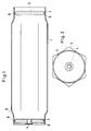
- the tube container shown in FIG. 1 consists of the tube 1 with the closed base 2 on the right in FIG. 1 and the partially open base 3.
- the container is used as a stackable compressed gas container.
- a reducing valve is screwed into the threaded opening 4 in the base 3.
- the tube container body is a hexagonal tube section as it is produced by rolling or drawing.
- the ends 5, 6 of the pipe section are brought into the circular cylindrical shape by pushing into a drawing ring.
- the diameter of 5 and 6 is slightly smaller than the inscribed circle of the hexagon.
- the bottom parts 5,6 have a radially open groove 7,8, in which a conventional O-ring 9 is inserted. They are pressed cold into the ends 5,6. So that they are already fixed in the pipe end for the next work step, they have an oversize compared to the clear width of 5 and 6.
- the tube container 1 comes on the bench and is rotated.
- a suitably profiled pressure roller possibly with a counter roller, is pressed in the area of the base parts 2, 3, so that a form-fitting connection between the tube body and the base part is created.
- the assembly which is suitable for the respective purpose, for example the coloring, the screwing in of the fitting and the filling.
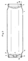
- FIG. 3 Another embodiment of the tube container is shown in FIG. 3.
- curved base parts 11, 12 are used and the protruding ends 10 of the circular cylindrical tube sections 5, 6 are rolled into the base parts during the pressure rolling.
- This version is mainly intended for thin-walled pipe containers.
- the pressure rolling of one of the circular cylindrical ends 5, 6 can also take place only after the installation of further parts, for. B. a piston with piston rod.
- the tube containers are preferably circular cylindrical over the entire length.
Landscapes
- Engineering & Computer Science (AREA)
- Mechanical Engineering (AREA)
- Filling Or Discharging Of Gas Storage Vessels (AREA)
- Tubes (AREA)
Priority Applications (2)
| Application Number | Priority Date | Filing Date | Title |
|---|---|---|---|
| DE8787730088T DE3780458D1 (de) | 1987-08-04 | 1987-08-04 | Verfahren zum herstellen eines rohrbehaelters. |
| EP19870730088 EP0302157B1 (fr) | 1987-08-04 | 1987-08-04 | Procédé de fabrication de récipients tubulaires |
Applications Claiming Priority (1)
| Application Number | Priority Date | Filing Date | Title |
|---|---|---|---|
| EP19870730088 EP0302157B1 (fr) | 1987-08-04 | 1987-08-04 | Procédé de fabrication de récipients tubulaires |
Publications (2)
| Publication Number | Publication Date |
|---|---|
| EP0302157A1 true EP0302157A1 (fr) | 1989-02-08 |
| EP0302157B1 EP0302157B1 (fr) | 1992-07-15 |
Family
ID=8198358
Family Applications (1)
| Application Number | Title | Priority Date | Filing Date |
|---|---|---|---|
| EP19870730088 Expired - Lifetime EP0302157B1 (fr) | 1987-08-04 | 1987-08-04 | Procédé de fabrication de récipients tubulaires |
Country Status (2)
| Country | Link |
|---|---|
| EP (1) | EP0302157B1 (fr) |
| DE (1) | DE3780458D1 (fr) |
Cited By (3)
| Publication number | Priority date | Publication date | Assignee | Title |
|---|---|---|---|---|
| RU2167019C1 (ru) * | 2000-02-03 | 2001-05-20 | Открытое акционерное общество "Центросвар" | Способ изготовления металлических баллонов |
| RU2185267C1 (ru) * | 2001-05-29 | 2002-07-20 | Зайченко Владимир Николаевич | Способ зайченко в.н. сварки вертикальных резервуаров |
| US20120000916A1 (en) * | 2010-07-02 | 2012-01-05 | Gm Global Technology Operations, Inc. | Composite pressure vessel and method of assembling the same |
Citations (5)
| Publication number | Priority date | Publication date | Assignee | Title |
|---|---|---|---|---|
| US1748576A (en) * | 1928-08-15 | 1930-02-25 | American Welding Company | Tank and method of making the same |
| DE541144C (de) * | 1924-08-01 | 1932-01-07 | Press Und Walzwerk Akt Ges | Verfahren zum Herstellen geschlossener rohrfoermiger Druckbehaelter, Kesselteile o. dgl. mit scheibenfoermigen Boeden |
| US1886803A (en) * | 1929-02-04 | 1932-11-08 | Fulton Sylphon Co | Tubular vessel and method of manufacture |
| US2854744A (en) * | 1956-02-17 | 1958-10-07 | Sydney R Crockett | Method of locking and sealing tubular structures |
| CH499348A (de) * | 1969-03-06 | 1970-11-30 | Bristol Myers Co | Verfahren zum Verschliessen von Metallbehältern und nach dem Verfahren verschlossener Metallbehälter |
-
1987
- 1987-08-04 DE DE8787730088T patent/DE3780458D1/de not_active Expired - Lifetime
- 1987-08-04 EP EP19870730088 patent/EP0302157B1/fr not_active Expired - Lifetime
Patent Citations (5)
| Publication number | Priority date | Publication date | Assignee | Title |
|---|---|---|---|---|
| DE541144C (de) * | 1924-08-01 | 1932-01-07 | Press Und Walzwerk Akt Ges | Verfahren zum Herstellen geschlossener rohrfoermiger Druckbehaelter, Kesselteile o. dgl. mit scheibenfoermigen Boeden |
| US1748576A (en) * | 1928-08-15 | 1930-02-25 | American Welding Company | Tank and method of making the same |
| US1886803A (en) * | 1929-02-04 | 1932-11-08 | Fulton Sylphon Co | Tubular vessel and method of manufacture |
| US2854744A (en) * | 1956-02-17 | 1958-10-07 | Sydney R Crockett | Method of locking and sealing tubular structures |
| CH499348A (de) * | 1969-03-06 | 1970-11-30 | Bristol Myers Co | Verfahren zum Verschliessen von Metallbehältern und nach dem Verfahren verschlossener Metallbehälter |
Cited By (4)
| Publication number | Priority date | Publication date | Assignee | Title |
|---|---|---|---|---|
| RU2167019C1 (ru) * | 2000-02-03 | 2001-05-20 | Открытое акционерное общество "Центросвар" | Способ изготовления металлических баллонов |
| RU2185267C1 (ru) * | 2001-05-29 | 2002-07-20 | Зайченко Владимир Николаевич | Способ зайченко в.н. сварки вертикальных резервуаров |
| US20120000916A1 (en) * | 2010-07-02 | 2012-01-05 | Gm Global Technology Operations, Inc. | Composite pressure vessel and method of assembling the same |
| US8757423B2 (en) * | 2010-07-02 | 2014-06-24 | GM Global Technology Operations LLC | Composite pressure vessel and method of assembling the same |
Also Published As
| Publication number | Publication date |
|---|---|
| DE3780458D1 (de) | 1992-08-20 |
| EP0302157B1 (fr) | 1992-07-15 |
Similar Documents
| Publication | Publication Date | Title |
|---|---|---|
| EP0850114B1 (fr) | Procede et dispositif permettant de produire des tuyaux fluotournes, a extremites a parois interieures epaissies | |
| DE3545554C2 (fr) | ||
| DE2736635C2 (de) | Schraubverbindung zwischen den Rohrstäben und einem Knotenstück von Knotenpunktverbindungen eines Raumfachwerks | |
| EP2101935A1 (fr) | Pièce et procédé pour le formage par explosion | |
| DE637797C (de) | Nietverbindung mittels Hohlniets und seinen Hohlraum fuellenden Schliessbolzens | |
| DE3148498C2 (de) | Verfahren zur Herstellung eines doppelwandigen Rohres für den Feststofftransport | |
| CH687816A5 (de) | Sicherheitslenksaeule. | |
| DE3229044C2 (fr) | ||
| DE4214557A1 (de) | Verfahren zum hydraulischen aufweiten von geschlossenen hohlprofilen | |
| EP0302157B1 (fr) | Procédé de fabrication de récipients tubulaires | |
| DE2729677C3 (de) | Verfahren und Vorrichtung zum Verbinden von zwei dünnwandigen Rohren gleichen Durchmessers | |
| DE19625554C2 (de) | Verfahren und Einrichtung zum drehfesten Verbinden einer Welle mit mindestens einem auf der Welle angeordnetem Teil | |
| DE4341206A1 (de) | An mindestens einem Wandungsteil befestigtes Aufnahmeteil | |
| DE1755384C2 (de) | Verfahren zur Herstellung von Lenkrohrmuffen für Fahrräder o.dgl. | |
| WO2021180608A1 (fr) | Procédé de fabrication d'une partie d'arbre de direction d'un arbre de direction destiné à un véhicule à moteur, procédé de fabrication d'un arbre de direction destiné à un véhicule à moteur, partie d'arbre de direction d'un arbre de direction destiné à un véhicule à moteur, arbre de direction de véhicule à moteur et colonne de direction de véhicule à moteur | |
| DE4334230A1 (de) | Verfahren zum Befestigen eines Profilteils in einem das Profilteil umgreifenden Hohlprofil | |
| DE19815244A1 (de) | Verfahren und Vorrichtung zum Herstellen von metallischen Hohlkörpern mit Beul-Struktur | |
| DE19740323A1 (de) | Verfahren zum Herstellen von Hohlprofilen, insbesondere von Rohren | |
| WO2008012043A1 (fr) | Procédé et dispositif pour produire une liaison arbre-moyeu | |
| DE102014004329A1 (de) | Verfahren und Vorrichtung zum Bearbeiten von stranggepessten Profilabschnitten aus Magnesium oder Magnesiumlegierungen und ein daraus hergestelltes Leichtbauelement | |
| DE2227955A1 (de) | Rohr fuer einen oberflaechenkondensator | |
| EP0303845A1 (fr) | Arbre creux et procédé pour sa fabrication | |
| DE2215584A1 (de) | Verfahren und Vorrichtung zur Herstellung von Muffenenden an in sich geschlossenen Profilen | |
| DE19702719C1 (de) | Verfahren zur Herstellung eines metallischen Rohrverbinders | |
| DE19532953A1 (de) | Verfahren und Vorrichtung zur Herstellung von drückgewalzten Rohren mit inneren Wandverdickungen |
Legal Events
| Date | Code | Title | Description |
|---|---|---|---|
| PUAI | Public reference made under article 153(3) epc to a published international application that has entered the european phase |
Free format text: ORIGINAL CODE: 0009012 |
|
| AK | Designated contracting states |
Kind code of ref document: A1 Designated state(s): AT BE CH DE ES FR GB GR IT LI LU NL SE |
|
| RBV | Designated contracting states (corrected) |
Designated state(s): DE FR GB IT SE |
|
| RIN1 | Information on inventor provided before grant (corrected) |
Inventor name: TRAEGER, HERBERT DIPL.-ING. Inventor name: JANSSEN, MANFRED, DR.-ING. |
|
| 17P | Request for examination filed |
Effective date: 19890310 |
|
| 17Q | First examination report despatched |
Effective date: 19900710 |
|
| GRAA | (expected) grant |
Free format text: ORIGINAL CODE: 0009210 |
|
| AK | Designated contracting states |
Kind code of ref document: B1 Designated state(s): DE FR GB IT SE |
|
| REF | Corresponds to: |
Ref document number: 3780458 Country of ref document: DE Date of ref document: 19920820 |
|
| ET | Fr: translation filed | ||
| ITF | It: translation for a ep patent filed | ||
| GBT | Gb: translation of ep patent filed (gb section 77(6)(a)/1977) | ||
| PLBE | No opposition filed within time limit |
Free format text: ORIGINAL CODE: 0009261 |
|
| STAA | Information on the status of an ep patent application or granted ep patent |
Free format text: STATUS: NO OPPOSITION FILED WITHIN TIME LIMIT |
|
| 26N | No opposition filed | ||
| PGFP | Annual fee paid to national office [announced via postgrant information from national office to epo] |
Ref country code: GB Payment date: 19930714 Year of fee payment: 7 |
|
| PGFP | Annual fee paid to national office [announced via postgrant information from national office to epo] |
Ref country code: FR Payment date: 19930720 Year of fee payment: 7 |
|
| PGFP | Annual fee paid to national office [announced via postgrant information from national office to epo] |
Ref country code: SE Payment date: 19930723 Year of fee payment: 7 |
|
| PGFP | Annual fee paid to national office [announced via postgrant information from national office to epo] |
Ref country code: DE Payment date: 19930924 Year of fee payment: 7 |
|
| PG25 | Lapsed in a contracting state [announced via postgrant information from national office to epo] |
Ref country code: GB Effective date: 19940804 |
|
| PG25 | Lapsed in a contracting state [announced via postgrant information from national office to epo] |
Ref country code: SE Effective date: 19940805 |
|
| EAL | Se: european patent in force in sweden |
Ref document number: 87730088.9 |
|
| GBPC | Gb: european patent ceased through non-payment of renewal fee |
Effective date: 19940804 |
|
| PG25 | Lapsed in a contracting state [announced via postgrant information from national office to epo] |
Ref country code: FR Effective date: 19950428 |
|
| PG25 | Lapsed in a contracting state [announced via postgrant information from national office to epo] |
Ref country code: DE Effective date: 19950503 |
|
| EUG | Se: european patent has lapsed |
Ref document number: 87730088.9 |
|
| REG | Reference to a national code |
Ref country code: FR Ref legal event code: ST |
|
| PG25 | Lapsed in a contracting state [announced via postgrant information from national office to epo] |
Ref country code: IT Free format text: LAPSE BECAUSE OF NON-PAYMENT OF DUE FEES;WARNING: LAPSES OF ITALIAN PATENTS WITH EFFECTIVE DATE BEFORE 2007 MAY HAVE OCCURRED AT ANY TIME BEFORE 2007. THE CORRECT EFFECTIVE DATE MAY BE DIFFERENT FROM THE ONE RECORDED. Effective date: 20050804 |