EP0302226B1 - Hinterradaufhängungssystem für Fahrzeuge - Google Patents
Hinterradaufhängungssystem für Fahrzeuge Download PDFInfo
- Publication number
- EP0302226B1 EP0302226B1 EP88110420A EP88110420A EP0302226B1 EP 0302226 B1 EP0302226 B1 EP 0302226B1 EP 88110420 A EP88110420 A EP 88110420A EP 88110420 A EP88110420 A EP 88110420A EP 0302226 B1 EP0302226 B1 EP 0302226B1
- Authority
- EP
- European Patent Office
- Prior art keywords
- lateral link
- link means
- lateral
- wheel
- suspension system
- Prior art date
- Legal status (The legal status is an assumption and is not a legal conclusion. Google has not performed a legal analysis and makes no representation as to the accuracy of the status listed.)
- Expired - Lifetime
Links
- 239000000725 suspension Substances 0.000 title claims description 30
- 238000006073 displacement reaction Methods 0.000 claims description 19
- 230000035939 shock Effects 0.000 claims description 7
- 241001247986 Calotropis procera Species 0.000 description 24
- 230000008859 change Effects 0.000 description 5
- 230000006835 compression Effects 0.000 description 4
- 238000007906 compression Methods 0.000 description 4
- 230000003247 decreasing effect Effects 0.000 description 2
- 238000010586 diagram Methods 0.000 description 2
- 230000004048 modification Effects 0.000 description 2
- 238000012986 modification Methods 0.000 description 2
- 230000004044 response Effects 0.000 description 2
- 230000008901 benefit Effects 0.000 description 1
- 238000006243 chemical reaction Methods 0.000 description 1
- 238000013016 damping Methods 0.000 description 1
- 230000007246 mechanism Effects 0.000 description 1
Images


Classifications
-
- B—PERFORMING OPERATIONS; TRANSPORTING
- B60—VEHICLES IN GENERAL
- B60G—VEHICLE SUSPENSION ARRANGEMENTS
- B60G3/00—Resilient suspensions for a single wheel
- B60G3/18—Resilient suspensions for a single wheel with two or more pivoted arms, e.g. parallelogram
- B60G3/20—Resilient suspensions for a single wheel with two or more pivoted arms, e.g. parallelogram all arms being rigid
- B60G3/22—Resilient suspensions for a single wheel with two or more pivoted arms, e.g. parallelogram all arms being rigid a rigid arm forming the axle housing
-
- B—PERFORMING OPERATIONS; TRANSPORTING
- B60—VEHICLES IN GENERAL
- B60G—VEHICLE SUSPENSION ARRANGEMENTS
- B60G3/00—Resilient suspensions for a single wheel
- B60G3/18—Resilient suspensions for a single wheel with two or more pivoted arms, e.g. parallelogram
- B60G3/28—Resilient suspensions for a single wheel with two or more pivoted arms, e.g. parallelogram at least one of the arms itself being resilient, e.g. leaf spring
- B60G3/285—Resilient suspensions for a single wheel with two or more pivoted arms, e.g. parallelogram at least one of the arms itself being resilient, e.g. leaf spring the arm being essentially parallel to the longitudinal axis of the vehicle
-
- B—PERFORMING OPERATIONS; TRANSPORTING
- B60—VEHICLES IN GENERAL
- B60G—VEHICLE SUSPENSION ARRANGEMENTS
- B60G2200/00—Indexing codes relating to suspension types
- B60G2200/10—Independent suspensions
- B60G2200/18—Multilink suspensions, e.g. elastokinematic arrangements
- B60G2200/182—Multilink suspensions, e.g. elastokinematic arrangements with one longitudinal arm or rod and lateral rods
-
- B—PERFORMING OPERATIONS; TRANSPORTING
- B60—VEHICLES IN GENERAL
- B60G—VEHICLE SUSPENSION ARRANGEMENTS
- B60G2202/00—Indexing codes relating to the type of spring, damper or actuator
- B60G2202/30—Spring/Damper and/or actuator Units
- B60G2202/31—Spring/Damper and/or actuator Units with the spring arranged around the damper, e.g. MacPherson strut
- B60G2202/312—The spring being a wound spring
Definitions
- the present invention relates to a vehicle suspension system and more particularly to a rear suspension system of a motor vehicle.
- Conventional independent type vehicle rear suspension systems include a so-called trailing arm type and a semi-trailing arm type.
- These types of suspension systems include a trailing arm extending in a longitudinal direction of the vehicle body and having a front end attached to the vehicle body for vertical swinging movements, the trailing arm being secured at the rear end to a hub carrier which carries a rear wheel hub.
- a substantially vertically extending damping strut is provided between the rear end portion of the trailing arm and the vehicle body.
- the suspension systems of these types are advantageous in that they are simple in structure so that the overall weight can be decreased.
- the suspension systems of these types require trailing arm of substantial cross-sectional area in order to ensure an adequate lateral rigidity.
- the front end of the trailing arm must be attached to the vehicle body at laterally spaced positions. As the results, the trailing arm must be of a substantial dimension and therefore of an increased weight.
- Japanese laid-open utility model 56-62205 proposes, in a vehicle rear suspension system including a trailing arm having a front end mounted on a vehicle body for vertical swinging movements and a rear end carrying a wheel hub, to provide a pair of vertically spaced lateral links which are pivotably connected at the laterally outward ends to the rear end portions of the trailing arm and at the laterally inward ends to the vehicle body.
- This type of suspension system is advantageous in that the lateral links supports the trailing arm so that the trailing arm may not be required to possess by itself a substantial lateral rigidity.
- US-A-4 269 432 shows a vehicle rear suspension system in which a longitudinal arm is connected at a rear end with a rear wheel support member through a pivotable connection.
- the longitudinal member is not connected with the rear wheel support member so that a rotational moment about the axis of the rear wheel can be transmitted between these members.
- the structure shown in DE-A-20 38 880 and in US-A-4 269 432 has a triangular upper arm having an inner end portion pivotably connected with the vehicle body through longitudinally spaced pivot means.
- the triangular upper arm used in either of the references DE-A-20 38 880 and US-A-4 269 432 is considered disadvantageous in that the vehicle body must have a space for allowing swinging movements of the arm. Providing such space is not easy because there are several link members which must be located in this area and the triangular arm must be arranged in a manner that interference with these other members can be avoided.
- the second lateral link means is located forwardly of the rotational centre of the rear wheel so that an effective control of the camber angle is possible.
- the shock absorbing means is located rearwardly of the second lateral link means and forwardly of the third lateral link means so that the shock absorbing means can be operated effectively. Because the shock absorbing means is located rearwardly of the second lateral link means it becomes possible to decrease the stroke of the second lateral link means under a vertical swinging movement of the swing arm means because the second lateral link means can be located closer to the swing axis of the swing arm means than in an arrangement wherein the second lateral link means is located rearward the shock absorbing means. Further, it is possible to increase the stroke of the shock absorbing means.
- the orientation of the wheel carrying means and therefore that of the rear wheel is determined only by the three lateral link means. Therefore, it becomes possible to control the toe-angle and the camber angle of the rear wheel in a desired manner under either or all of upward bumping and downward rebouncing of the rear wheel and side and longitudinal forces applied to the rear wheel by simply determining the arrangements of the lateral link means. For example, the inclination of each lateral link means in a horizontal plane and that in a vertical plane may appropriately be determined. In addition or alternatively, the lengths of the respective lateral link means, the positions of connections of the lateral link means to the wheel carrying means and the lateral rigidity of the connections between the lateral link means to the wheel carrying means may appropriately be determined to obtain desired results.
- the swing arm means may simply possess strength and rigidity sufficient for transmitting longitudinal forces and rotating forces about a lateral axis. It is necessary that the swing arm means does not constrain the wheel carrying means so that the orientation of the wheel carrying means be controlled by the three lateral link means.
- the swing arm means may have low lateral rigidity so that the swing arm means be capable of deflecting in lateral directions under upward bouncing and downward rebouncing of the rear wheel.
- the swing arm means may be connected with the wheel carrying means so that a rotation about a vertical axis or a lateral relative displacement is permitted.
- one of the lateral link means is connected to the wheel carrying means at a position higher than positions where the other two lateral link means are connected with the wheel carrying means, the said positions being so located that a cornering force acting point on the rear wheel is between imaginary lines passing through the first mentioned position and respective ones of the second mentioned positions.
- the first mentioned position is located above the rotation axis of the rear wheel and the second mentioned positions are located below the rotation axis.
- the aforementioned other two link means are preferably arranged so that projections in a horizontal plane of extensions of their longitudinal axes intersect each other outward said rear wheel. This particular arrangement is effective to produce a toe-in movement of the rear wheel under a braking force.
- the second lateral link means is connected to the wheel carrying means at a position above the rotation axis of the rear wheel, the first lateral link means being connected at a position below and forward the rotation axis and the third lateral link means being connected at a position below and rearward the rotation axis, the second lateral link means being shorter than the third lateral link means.
- the first lateral link means is preferably connected to the wheel carrying means forward a line passing through the cornering force acting point on the rear wheel and the position where the second lateral link is connected to the wheel carrying means, the third lateral link means being connected to the wheel carrying means rearward of the aforementioned line, the distance between the position of connection of the second lateral link means and the aforementioned line being smaller than that between the position of connection of the third lateral link means and the aforementioned line.
- the arrangement is effective to produce a toe-in movement of the rear wheel under an inwardly directed side force.
- the second and third link means are arranged rearward the first link means, the second link means being above and shorter than the third lateral link means, projections in a vertical transverse plane of longitudinal axes of the second and third lateral link means intersecting each other at a point inward the rear wheel, the first link means being shorter than the second and third link means.
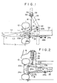
- a vehicle rear left wheel 10 which is carried by a wheel carrying member 12 for rotation about a rotation axis L4.
- a rear suspension system 14 which includes a longitudinally extending swing arm 18.
- the swing arm 18 is connected at the front end with a bracket 29 provided on a frame 28 of the vehicle body 16 by means of a rubber bush 39 and a laterally extending pin 38 so that the arm 38 is vertically swingable about a horizontal axis.
- the rear end of the swing arm 18 is secured to the wheel carrying member 12 by means of bolts 30.
- the suspension system 14 further includes a first lateral link 20, a second lateral link 22 and a third lateral link 24.
- the first lateral link 20 extends substantially transversely with respect to the vehicle body 16 and has a transverse outward end connected with the wheel carrying member 12 through a rubber bush 20a for swinging movement about a substantially longitudinal axis.
- the transverse inward end of the first lateral link 20 is connected with the body frame 28 through a rubber bush 20b for swinging movement about a substantially longitudinal axis.
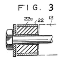
- the second and third lateral links 22 and 24 are connected at one ends respectively through rubber bushes 22a and 24a to the wheel carrying member 12 for swinging movements about substantially longitudinal axes, and at the other ends respectively through rubber bushes 22b and 24b to a rear sub-frame 32 of the vehicle body 16 for swinging movements about substantially longitudinal axes.
- the rubber bush 22a as typical example of the aforementioned rubber bushes. It should be noted that the other bushes have similar structures.
- a substantially vertically extending strut assembly 26 which comprises a coil spring 34 and an oleo damper 36.
- the strut assembly 26 is pivotably connected at the lower end with the wheel carrying member 12 and connected at the upper end to the vehicle body 16 so as to allow a certain degree of angular movement.
- the first lateral link 20 is inclined rearward and downward and has a length shorter than those of the other two lateral links 22 and 24.
- the second lateral link 22 is inclined slightly forward and upward whereas the third lateral link 24 is inclined slightly downward.
- the swing arm 18 is swung about the pin 38 so that the wheel center 40 is moved along an arcuate path having a center of arc at the axis of the pin 38.
- the wheel carrying member 12 is laterally supported by three lateral links 20, 22 and 24 which also swing in vertical directions to produce lateral displacements at the outward ends.
- the laterally outward end of the first lateral link 20 is slightly displaced outward but the displacement is small because the link 20 is inclined rearward.
- the outer end of the second lateral link 22 is displaced inward in response to an upward bump of the wheel.
- the outer end of the third lateral link 24 is displaced outward, the distance of displacement being larger than that of the outer end of the first lateral link 20. Since the outer ends of the first and second lateral links 20 and 24 are located forward the outer end of the third lateral link 24, there is produced a slight toe-in movement. Further, there is produced a decrease in the camber angle. Under a downward rebouncing of the wheel, there are produced a slight toe-out movement and a slight increase in the camber angle.
- the toe-angle of the wheel is changed as shown by a curve a in Figure 5(a).
- the toe-angle change in the prior art suspension system of the laid-open Japanese utility model 56-62205 is shown by a curve b in Figure 5 (a).
- the advantage of the present invention will be apparent from this diagram.
- the third lateral link 24 has a length sufficiently large as compared with the first lateral link 20, there will be no noticeable displacement in the outer end of the third lateral link 24 so that the toe-angle change will be as shown by a curve c.
- the camber angle is changed as shown by a curve M1 in Figure 5(b) due to the arrangements of the second and third lateral links 22 and 24 as described previously.
- the camber angle is decreased in response to an upward bumping of the wheel and the decrease in the camber angle causes an increase in the tread.
- the tread changes as shown by a curve M2 in Figure 5(c).
- the camber angle will change as shown by a curve N1 in Figure 5(b).
- the tread will change as shown by a curve N2 in Figure 5(c).
- the swing arm 18 is of a cross-sectional configuration which provides a certain degree of deflection in lateral direction of the vehicle body, the swing arm 18 is laterally deflected as necessary as the wheel carrying member 12 is displaced as described above. Further, the rubber bush 39 permits a certain amount of lateral displacement of the swing arm.
- the rubber bush 39 includes an outer tube 39a and an inner tube 39.
- a resilient rubber 39c is disposed between and adhered to the outer and inner tubes 39a and 39b.
- the pin 38 is inserted into the inner tube 39b to secure the inner tube 39b to the bracket 29 of the frame 28.
- the outer tube 39a is welded to the swing arm 18. It will be understood in Figure 5 that the rubber bush 39 is deflected as shown by phantom lines to permit a lateral displacement of the swing arm 18.
- the embodiment shown therein is different from the previous embodiment in that the second lateral link 22 is connected to the wheel carrying member 12 at a location above and forward of the wheel center 40.
- the second lateral link 22 is connected to the wheel carrying member 12 at a location above and forward of the wheel center 40.
- a moment produced by the side force F acting on a point P1 is balanced by a moment produced by an axial compression force F3 in the third lateral link 24.
- Figure 7 shows another embodiment of the present invention in which corresponding parts are designated by the same reference numerals.
- an imaginary line L7 which passes through the center of the rubber bush 22a and the side force acting point P1 on the wheel 10.
- the distance l1 between the center of the rubber bush 20a and the imaginary line L7 is smaller than the distance l2 between the center of the rubber bush 24a and the imaginary line L7 .
- the axial compression force F1 produced in the first lateral link 20 under the side force F becomes greater than that F3 in the third lateral link 24.
- Such difference in the axial forces F1 and F3 produces a difference in deformations of the rubber bushes 20a and 24a and causes a slight toe-in movement of the wheel 10.
- Figure 8 shows a modification of the arrangement of Figure 7 and a similar toe-in movement of the wheel 10 is produced under a side force F.
- the embodiment shown therein is different from the previously described embodiments in that the rubber bush 39 for connecting the front end of the swing arm 18 has an axis 39l which is inwardly and rearwardly inclined with respect to a transverse direction of the vehicle body.
- the swing arm 18 is deflected inward as shown by phantom lines to permit inward displacement of the wheel carrying member 12.
- an axial deformation is produced in the rubber bush 39 causing a slight rearward displacement of the swing arm 18 and therefore a corresponding rearward displacement of the wheel carrying member 12.
Landscapes
- Engineering & Computer Science (AREA)
- Mechanical Engineering (AREA)
- Vehicle Body Suspensions (AREA)
Claims (5)
- Hinterradaufhängungssystem für Fahrzeuge, umfassend eine Schwenkarmeinrichtung (18), die sich im wesentlichen in Längsrichtung erstreckt und einen elastisch mit der Fahrzeugkarosserie gekoppelten vorderen Abschnitt aufweist, der vertikale Schwenkbewegungen um eine im wesentlichen horizontale Querachse (391) ausführt und eine bestimmte seitliche Verschiebung des Schwenkarms zuläßt,
eine Radträgereinrichtung (12) zur Aufnahme eines Hinterrades (10), das sich um eine Drehachse (L4) dreht, wobei die Radträgereinrichtung (12) starr mit dem hinteren Ende der Schwenkarmeinrichtung (18) in der Weise verbunden ist, daß ein Drehmoment um die Achse des Hinterrades zwischen der Schwenkarmeinrichtung (18) und der Radträgereinrichtung (12) übertragen werden kann,
eine erste (20), zweite (22) und dritte (24) Querlenkereinrichtung, die sich im wesentlichen in Querrichtung der Fahrzeugkarosserie erstrecken und die Anordnung des Hinterrades (10) kontrollieren, wobei die zweite Querlenkereinrichtung (22) oberhalb eines Drehmittelpunktes (40) des Hinterrades (10), die dritte Querlenkereinrichtung (24) unterhalb und hinter dem Drehmittelpunkt (40) des Hinterrades (10), die erste Querlenkereinrichtung (20) vor der dritten Querlenkereinrichtung (24) angeordnet ist,
und wobei jede der Querlenkereinrichtungen (20, 22, 24) ein transversales inneres Ende umfaßt, das mit der Fahrzeugkarosserie mittels eines einzelnen Drehgelenks verbunden ist,
eine zwischen der Radträgereinrichtung und der Fahrzeugkarosserie angeordnete Stoßdämpfereinrichtung (26) zur Aufnahme senkrechter Schwingungsbeanspruchungen,
dadurch gekennzeichnet, daß
die zweite Querlenkereinrichtung (22) vor dem Drehmittelpunkt (40) des Hinterrades (10) angeordnet ist,
die erste Querlenkereinrichtung (20) eine kürzere Länge hat als die beiden anderen Querlenkereinrichtungen (22, 24),
und daß die Stoßdämpfereinrichtung (26) hinter der zweiten Querlenkereinrichtung (22) und vor der dritten Querlenkereinrichtung (24) angeordnet ist. - Hinterradaufhängungssystem für Fahrzeuge gemäß Anspruch 1, bei dem die dritte Querlenkereinrichtung (24) unter und hinter der zweiten Querlenkereinrichtung (22) angeordnet ist.
- Hinterradaufhängungssystem für Fahrzeuge gemäß Anspruch 1 oder 2, bei dem die erste Querlenkereinrichtung (20) so angeordnet ist, daß das äußere Ende relativ zum inneren Ende nach hinten gerichtet ist und eine Achse aufweist, deren Verlängerung eine Verlängerung der Achse der dritten Querlenkereinrichtung (24) schneidet.
- Hinterradaufhängungssystem für Fahrzeuge gemäß einem der Ansprüche 1 bis 3, bei dem das innere Ende der dritten Querlenkereinrichtung (24) mit einem an der Fahrzeugkarosserie (16) vorgesehenen Hilfsrahmen (32) verbunden ist, so daß es sich in Querrichtung der Fahrzeugkarosserie (16) erstreckt.
- Hinterradaufhängungssystem für Fahrzeuge gemäß einem der Ansprüche 1 bis 4, bei dem die dritte Querlenkereinrichtung (24) eine größere Länge aufweist als jede der zweiten (22) und ersten (20) Querlenkereinrichtungen.
Applications Claiming Priority (14)
| Application Number | Priority Date | Filing Date | Title |
|---|---|---|---|
| JP16153583A JPS6053408A (ja) | 1983-09-02 | 1983-09-02 | 自動車のリヤサスペンション |
| JP16153883A JPS6053411A (ja) | 1983-09-02 | 1983-09-02 | 自動車のリヤサスペンション |
| JP161538/83 | 1983-09-02 | ||
| JP16154183A JPS6053414A (ja) | 1983-09-02 | 1983-09-02 | 自動車のリヤサスペンション |
| JP161536/83 | 1983-09-02 | ||
| JP161535/83 | 1983-09-02 | ||
| JP161539/83 | 1983-09-02 | ||
| JP16153983A JPS6053412A (ja) | 1983-09-02 | 1983-09-02 | 自動車のリヤサスペンション |
| JP161541/83 | 1983-09-02 | ||
| JP16153783A JPS6053410A (ja) | 1983-09-02 | 1983-09-02 | 自動車のリヤサスペンション |
| JP16153683A JPS6053409A (ja) | 1983-09-02 | 1983-09-02 | 自動車のリヤサスペンション |
| JP161537/83 | 1983-09-02 | ||
| JP168723/83 | 1983-09-13 | ||
| JP16872383A JPS6060016A (ja) | 1983-09-13 | 1983-09-13 | 自動車のリヤサスペンシヨン |
Related Parent Applications (1)
| Application Number | Title | Priority Date | Filing Date |
|---|---|---|---|
| EP84110400.3 Division | 1984-08-31 |
Publications (3)
| Publication Number | Publication Date |
|---|---|
| EP0302226A2 EP0302226A2 (de) | 1989-02-08 |
| EP0302226A3 EP0302226A3 (en) | 1989-05-24 |
| EP0302226B1 true EP0302226B1 (de) | 1993-11-24 |
Family
ID=27566225
Family Applications (2)
| Application Number | Title | Priority Date | Filing Date |
|---|---|---|---|
| EP88110420A Expired - Lifetime EP0302226B1 (de) | 1983-09-02 | 1984-08-31 | Hinterradaufhängungssystem für Fahrzeuge |
| EP84110400A Expired - Lifetime EP0136563B2 (de) | 1983-09-02 | 1984-08-31 | Hinterradaufhängungssystem für Fahrzeug |
Family Applications After (1)
| Application Number | Title | Priority Date | Filing Date |
|---|---|---|---|
| EP84110400A Expired - Lifetime EP0136563B2 (de) | 1983-09-02 | 1984-08-31 | Hinterradaufhängungssystem für Fahrzeug |
Country Status (3)
| Country | Link |
|---|---|
| US (2) | US4815755A (de) |
| EP (2) | EP0302226B1 (de) |
| DE (2) | DE3486249T2 (de) |
Cited By (1)
| Publication number | Priority date | Publication date | Assignee | Title |
|---|---|---|---|---|
| US7325820B2 (en) | 2005-07-11 | 2008-02-05 | Ford Global Technologies, Llc | Independent rear suspension |
Families Citing this family (60)
| Publication number | Priority date | Publication date | Assignee | Title |
|---|---|---|---|---|
| EP0302226B1 (de) * | 1983-09-02 | 1993-11-24 | Mazda Motor Corporation | Hinterradaufhängungssystem für Fahrzeuge |
| DE3448231C2 (de) * | 1983-09-22 | 1995-12-21 | Honda Motor Co Ltd | Einzelradaufhängung für ein Kraftfahrzeug |
| DE3434790A1 (de) * | 1983-09-22 | 1985-04-18 | Honda Giken Kogyo K.K., Tokio/Tokyo | Hinterradaufhaengung fuer ein kraftfahrzeug |
| CA1259641A (en) * | 1984-09-06 | 1989-09-19 | Kanji Kubo | Trailing arm joint structure |
| US4790560A (en) * | 1984-09-06 | 1988-12-13 | Honda Giken Kogyo Kabushiki Kaisha | Independent rear suspension for use on motor vehicles |
| DE3674021D1 (de) * | 1985-02-26 | 1990-10-18 | Mazda Motor | Hinterradaufhaengung fuer ein fahrzeug. |
| JPS61278407A (ja) * | 1985-06-03 | 1986-12-09 | Honda Motor Co Ltd | 独立懸架式リヤサスペンシヨン |
| CA1265823A (en) * | 1985-10-04 | 1990-02-13 | Keiichi Mitobe | Independent rear wheel suspension |
| JPS62191207A (ja) * | 1986-02-17 | 1987-08-21 | Toyota Motor Corp | 自動車の後輪懸架装置 |
| FR2595995B1 (fr) * | 1986-03-20 | 1988-07-08 | Peugeot | Suspension de roue independante, notamment arriere de vehicule et son application a une roue motrice |
| JPS63145112A (ja) * | 1986-12-09 | 1988-06-17 | Honda Motor Co Ltd | 自動車のリヤサスペンシヨン装置 |
| JPH07100403B2 (ja) * | 1986-12-15 | 1995-11-01 | マツダ株式会社 | 自動車のサスペンション装置 |
| US4756546A (en) * | 1987-03-13 | 1988-07-12 | Honda Giken Kogyo Kabushiki Kaisha | Rear wheel suspension device for front and rear wheel steering vehicle |
| FR2625140B1 (fr) * | 1987-12-29 | 1990-06-01 | Renault | Suspension pour vehicules automobiles |
| IT1212164B (it) * | 1987-12-30 | 1989-11-08 | Fiat Auto Spa | Sospensione posteriore per autoveicoli a ruote indipendenti |
| US5301932A (en) * | 1988-07-15 | 1994-04-12 | Suzuki Motor Corp. | Vehicular strut type suspension |
| US5009449A (en) * | 1988-07-27 | 1991-04-23 | Mazda Motor Corporation | Vehicle rear suspension system |
| JP2714969B2 (ja) * | 1989-01-13 | 1998-02-16 | マツダ株式会社 | 自動車のサスペンション装置 |
| US4998748A (en) * | 1989-04-04 | 1991-03-12 | Mazda Motor Corporation | Vehicle suspension system |
| FR2645475B1 (fr) * | 1989-04-11 | 1994-03-25 | Renault Regie Nale Usines | Suspension pour vehicules automobiles |
| US5348337A (en) * | 1991-12-27 | 1994-09-20 | Mazda Motor Corporation | Automobile suspension |
| EP0556464A1 (de) * | 1992-02-15 | 1993-08-25 | Volkswagen Aktiengesellschaft | Einzelradaufhängung für Hinterräder eines Kraftfahrzeugs |
| DE9422146U1 (de) * | 1993-11-29 | 1998-04-30 | Dr.Ing.H.C. F. Porsche Ag, 70435 Stuttgart | Radaufhängung |
| GB9514974D0 (en) * | 1995-07-21 | 1995-09-20 | Rover Group | A semi-trailing arm suspension for a vehicle |
| US6022034A (en) * | 1996-10-09 | 2000-02-08 | Toyota Jidosha Kabushiki Kaisha | Twist beam suspension |
| US5823552A (en) * | 1997-08-25 | 1998-10-20 | Chrysler Corporation | Strut type rear suspension |
| US6173978B1 (en) * | 1999-05-07 | 2001-01-16 | Zero Roll Suspension Corporation | Zero roll suspension system |
| GB9911633D0 (en) * | 1999-05-20 | 1999-07-21 | Randle Engineering Solutions L | Improved vehicle suspension |
| JP3945156B2 (ja) | 2000-12-19 | 2007-07-18 | マツダ株式会社 | 自動車のサスペンション装置 |
| US20040046350A1 (en) * | 2001-05-21 | 2004-03-11 | Wagner Engineering, Llc | Method and apparatus for suspending a vehicular wheel assembly |
| DE10253265A1 (de) * | 2002-11-15 | 2004-05-27 | Volkswagen Ag | Vierlenker-Hinterradachse für ein Kraftfahrzeug |
| US20040178600A1 (en) * | 2003-03-10 | 2004-09-16 | Wagner Engineering, Llc | Method and apparatus for suspending a vehicle |
| DE10311953B4 (de) * | 2003-03-18 | 2012-10-25 | Volkswagen Ag | Hinterradaufhängung für ein Kraftfahrzeug |
| JP2005225382A (ja) * | 2004-02-13 | 2005-08-25 | Honda Motor Co Ltd | 車両用リヤサスペンション装置 |
| US7494142B2 (en) * | 2005-07-01 | 2009-02-24 | Lehman Trikes U.S.A., Inc. | Swing arm with impact dampener |
| US7431315B2 (en) * | 2005-07-11 | 2008-10-07 | Ford Global Technologies, Llc | Vehicle suspension system with wheel support knuckle and trailing arm attached to toe link |
| JP4765484B2 (ja) * | 2005-08-25 | 2011-09-07 | 日産自動車株式会社 | サスペンション装置 |
| JP4258506B2 (ja) * | 2005-08-30 | 2009-04-30 | トヨタ自動車株式会社 | インホイールサスペンション |
| DE102006062889B4 (de) * | 2005-09-13 | 2014-06-26 | Ksm Castings Group Gmbh | Hilfsrahmen, insbesondere für Kraftfahrzeuge |
| JP4779582B2 (ja) * | 2005-11-10 | 2011-09-28 | 日産自動車株式会社 | インホイールドライブユニットのサスペンション装置 |
| US20080036168A1 (en) * | 2005-11-30 | 2008-02-14 | Wagner J T | Method and apparatus for suspending a vehicle |
| ITTO20060572A1 (it) | 2006-08-01 | 2008-02-02 | Sistemi Sospensioni Spa | Braccio longitudinale per una sospensione posteriore a ruote indipendenti per autoveicolo |
| GB2442716B (en) * | 2006-10-13 | 2011-05-04 | Ford Global Tech Llc | Independent rear suspension |
| JP2008195296A (ja) * | 2007-02-14 | 2008-08-28 | Honda Motor Co Ltd | サスペンション装置 |
| US8029021B2 (en) | 2007-03-16 | 2011-10-04 | Polaris Industries Inc. | Vehicle |
| FR2914586A1 (fr) * | 2007-04-03 | 2008-10-10 | Renault Sas | Train arriere multi-bras pour vehicule automobile |
| DE102007043121A1 (de) * | 2007-09-10 | 2009-03-12 | GM Global Technology Operations, Inc., Detroit | Verbundlenkerachse mit elastisch aufgehängtem Radträger |
| ITTO20070872A1 (it) * | 2007-12-03 | 2009-06-04 | Sistemi Sospensioni Spa | Braccio ibrido per sospensione posteriore a ruote indipendenti per autoveicolo |
| DE102007063545A1 (de) * | 2007-12-21 | 2009-06-25 | Dr. Ing. H.C. F. Porsche Aktiengesellschaft | Radaufhängung für die Hinterräder eines Kraftfahrzeugs |
| US7984915B2 (en) * | 2009-05-12 | 2011-07-26 | Honda Motor Co., Ltd. | Rear suspension with semi-active toe force compliance control |
| JP5005067B2 (ja) * | 2010-05-28 | 2012-08-22 | 本田技研工業株式会社 | サスペンション装置 |
| DE102011055572B4 (de) * | 2011-11-22 | 2025-05-22 | Dr. Ing. H.C. F. Porsche Aktiengesellschaft | Mehrlenker-Hinterradachse für ein Kraftfahrzeug |
| US9327587B2 (en) | 2012-05-31 | 2016-05-03 | Arctic Cat Inc. | Off-highway recreational vehicle |
| DE102012216822A1 (de) | 2012-09-19 | 2014-05-28 | Bayerische Motoren Werke Aktiengesellschaft | Fahrzeug-Radaufhängung der Schwertlenker-Bauart |
| DE102013202527A1 (de) * | 2013-02-15 | 2014-08-21 | Bayerische Motoren Werke Aktiengesellschaft | Hinterachse eines zweispurigen Fahrzeugs |
| DE102016210072B4 (de) | 2016-06-08 | 2023-12-07 | Ford Global Technologies, Llc | Radaufhängungseinheit für ein Kraftfahrzeug |
| DE102016210073A1 (de) | 2016-06-08 | 2017-12-14 | Ford Global Technologies, Llc | Radaufhängungseinheit für ein Kraftfahrzeug |
| DE202016103190U1 (de) | 2016-06-08 | 2016-07-08 | Ford Global Technologies, Llc | Radaufhängungseinheit für ein Kraftfahrzeug |
| TWI678297B (zh) * | 2017-10-20 | 2019-12-01 | 沃爾奇動力機電股份有限公司 | 獨立式後懸吊系統 |
| US11511581B1 (en) | 2021-06-16 | 2022-11-29 | Xtravel Suspension, Llc | Suspension system |
Citations (3)
| Publication number | Priority date | Publication date | Assignee | Title |
|---|---|---|---|---|
| DE923346C (de) * | 1952-05-28 | 1955-02-10 | Porsche Kg | Einzelradaufhaengung der Antriebsraeder von Kraftfahrzeugen |
| DE1938851A1 (de) * | 1968-08-20 | 1970-08-06 | Bayerische Motoren Werke Ag | Unabhaengige Aufhaengung der gelenkten Raeder von Kraftfahrzeugen,insbesondere Personenkraftwagen |
| GB2087322A (en) * | 1980-11-14 | 1982-05-26 | Bayerische Motoren Werke Ag | Single-wheel suspension |
Family Cites Families (21)
| Publication number | Priority date | Publication date | Assignee | Title |
|---|---|---|---|---|
| DE1151740B (de) * | 1957-02-28 | 1963-07-18 | Daimler Benz Ag | Einzelradaufhaengung fuer Fahrzeuge, insbesondere Kraftfahrzeuge |
| US3193302A (en) * | 1962-04-18 | 1965-07-06 | Harry Fergnson Res Ltd | Rear suspension mechanism for motor vehicles |
| FR1374788A (fr) * | 1962-12-01 | 1964-10-09 | Daimler Benz Ag | Bielle de guidage pour roues, en particulier de voitures automobiles |
| US3327803A (en) * | 1964-12-22 | 1967-06-27 | Gen Motors Corp | Independent rear wheel suspension |
| DE2027885B2 (de) * | 1970-06-06 | 1978-12-07 | Daimler-Benz Ag, 7000 Stuttgart | Radaufhängung für Kraftfahrzeuge |
| DE2038880A1 (de) * | 1970-08-05 | 1972-02-10 | Daimler Benz Ag | Radaufhaengung,insbesondere Hinterradaufhaengung an Kraftfahrzeugen |
| US4269432A (en) * | 1978-05-24 | 1981-05-26 | Toyo Kogyo Co., Ltd. | Independent wheel suspension for motor vehicles |
| JPS5662205A (en) * | 1979-10-26 | 1981-05-28 | Toshiba Corp | Fixed optical attenuator |
| EP0052154B1 (de) * | 1980-11-14 | 1984-05-16 | Bayerische Motoren Werke Aktiengesellschaft, Patentabteilung AJ-3 | Einzelradaufhängung für nicht gelenkte Räder von Kraftfahrzeugen, insbesondere von Personenkraftwagen |
| DE3068376D1 (en) * | 1980-11-14 | 1984-08-02 | Bayerische Motoren Werke Ag | Independent suspension for non-steered wheels of motor vehicles exhibiting a camber variation during suspension movement, especially for passenger vehicles |
| US4471974A (en) * | 1980-11-14 | 1984-09-18 | Bayerische Motoren Werke Ag | Individual wheel suspension for non-steered wheels of motor vehicles, especially automobiles |
| DE3048837C2 (de) * | 1980-12-23 | 1987-03-12 | Daimler-Benz Ag, 7000 Stuttgart | Unabhängige Radaufhängung |
| DE3048864C2 (de) * | 1980-12-23 | 1986-11-13 | Daimler-Benz Ag, 7000 Stuttgart | Achse, insbesondere Hinterachse für Personenkraftwagen, mit unabhängig von einander geführten Rädern |
| DE3048794C1 (de) * | 1980-12-23 | 1982-08-12 | Daimler-Benz Ag, 7000 Stuttgart | Unabhaengige Radaufhaengung fuer Kraftfahrzeuge |
| DE3136125C1 (de) * | 1981-09-11 | 1983-04-21 | Bayerische Motoren Werke AG, 8000 München | Verbundachse für Kraftfahrzeuge |
| US4529221A (en) * | 1982-04-30 | 1985-07-16 | Mazda Motor Corporation | Vehicle rear suspension mechanism |
| EP0302226B1 (de) * | 1983-09-02 | 1993-11-24 | Mazda Motor Corporation | Hinterradaufhängungssystem für Fahrzeuge |
| JPS6064006A (ja) * | 1983-09-19 | 1985-04-12 | Mazda Motor Corp | 自動車のリヤサスペンション |
| JPS6064009A (ja) * | 1983-09-19 | 1985-04-12 | Mazda Motor Corp | 自動車のリヤサスペンシヨン |
| JPS6067207A (ja) * | 1983-09-26 | 1985-04-17 | Mazda Motor Corp | 自動車のリヤサスペンション |
| JPS61196810A (ja) * | 1985-02-26 | 1986-09-01 | Mazda Motor Corp | 自動車のリヤサスペンシヨン |
-
1984
- 1984-08-31 EP EP88110420A patent/EP0302226B1/de not_active Expired - Lifetime
- 1984-08-31 DE DE88110420T patent/DE3486249T2/de not_active Expired - Lifetime
- 1984-08-31 EP EP84110400A patent/EP0136563B2/de not_active Expired - Lifetime
- 1984-08-31 DE DE8484110400T patent/DE3480186D1/de not_active Expired
-
1987
- 1987-04-20 US US07/043,479 patent/US4815755A/en not_active Expired - Lifetime
-
1988
- 1988-11-03 US US07/266,869 patent/US4930805A/en not_active Expired - Lifetime
Patent Citations (3)
| Publication number | Priority date | Publication date | Assignee | Title |
|---|---|---|---|---|
| DE923346C (de) * | 1952-05-28 | 1955-02-10 | Porsche Kg | Einzelradaufhaengung der Antriebsraeder von Kraftfahrzeugen |
| DE1938851A1 (de) * | 1968-08-20 | 1970-08-06 | Bayerische Motoren Werke Ag | Unabhaengige Aufhaengung der gelenkten Raeder von Kraftfahrzeugen,insbesondere Personenkraftwagen |
| GB2087322A (en) * | 1980-11-14 | 1982-05-26 | Bayerische Motoren Werke Ag | Single-wheel suspension |
Non-Patent Citations (1)
| Title |
|---|
| ATZ (1971) 7, p. 247-254 * |
Cited By (1)
| Publication number | Priority date | Publication date | Assignee | Title |
|---|---|---|---|---|
| US7325820B2 (en) | 2005-07-11 | 2008-02-05 | Ford Global Technologies, Llc | Independent rear suspension |
Also Published As
| Publication number | Publication date |
|---|---|
| EP0302226A3 (en) | 1989-05-24 |
| DE3486249T2 (de) | 1994-03-17 |
| EP0136563A2 (de) | 1985-04-10 |
| US4815755A (en) | 1989-03-28 |
| DE3486249D1 (de) | 1994-01-05 |
| EP0302226A2 (de) | 1989-02-08 |
| EP0136563B1 (de) | 1989-10-18 |
| EP0136563A3 (en) | 1985-07-03 |
| EP0136563B2 (de) | 1994-04-20 |
| DE3480186D1 (en) | 1989-11-23 |
| US4930805A (en) | 1990-06-05 |
Similar Documents
| Publication | Publication Date | Title |
|---|---|---|
| EP0302226B1 (de) | Hinterradaufhängungssystem für Fahrzeuge | |
| KR0180370B1 (ko) | 자동차의 조향륜 현가장치 | |
| EP0378219B1 (de) | Fahrzeugaufhängungssystem | |
| EP0754575B1 (de) | Schräglenker-Hinterachse für ein Fahrzeug | |
| US4159128A (en) | Vehicle suspension system including wheel-tilting mechanism | |
| US4802688A (en) | Double link type suspension system | |
| EP0193847B1 (de) | Hinterradaufhängung für ein Fahrzeug | |
| KR0131300B1 (ko) | 자동차의 조향륜 현가장치 | |
| US4715615A (en) | Vehicle rear-suspension system | |
| JP2518349B2 (ja) | 車輌用リヤサスペンション | |
| KR910008158B1 (ko) | 차량의 리어서스펜션 | |
| EP0301782B1 (de) | Aufhängeeinheit für Fahrzeugrad | |
| EP0355362B1 (de) | Hinterradaufhängungssystem | |
| US4087115A (en) | Motor vehicle rear wheel suspension | |
| JPS6248602B2 (de) | ||
| US4738466A (en) | Vehicle suspension | |
| JPS6053412A (ja) | 自動車のリヤサスペンション | |
| JPS6248608B2 (de) | ||
| JPS6064009A (ja) | 自動車のリヤサスペンシヨン | |
| JPS6053409A (ja) | 自動車のリヤサスペンション | |
| JPH0577521B2 (de) | ||
| JPS6248605B2 (de) | ||
| JPH08300922A (ja) | 車両の操向駆動輪懸架装置 | |
| JPH0542807A (ja) | 3リンク式車輪独立懸架装置 | |
| JPS6053413A (ja) | 自動車のリヤサスペンション |
Legal Events
| Date | Code | Title | Description |
|---|---|---|---|
| PUAI | Public reference made under article 153(3) epc to a published international application that has entered the european phase |
Free format text: ORIGINAL CODE: 0009012 |
|
| 17P | Request for examination filed |
Effective date: 19881108 |
|
| AC | Divisional application: reference to earlier application |
Ref document number: 136563 Country of ref document: EP |
|
| AK | Designated contracting states |
Kind code of ref document: A2 Designated state(s): DE FR GB |
|
| PUAL | Search report despatched |
Free format text: ORIGINAL CODE: 0009013 |
|
| AK | Designated contracting states |
Kind code of ref document: A3 Designated state(s): DE FR GB |
|
| 17Q | First examination report despatched |
Effective date: 19891212 |
|
| GRAA | (expected) grant |
Free format text: ORIGINAL CODE: 0009210 |
|
| AC | Divisional application: reference to earlier application |
Ref document number: 136563 Country of ref document: EP |
|
| AK | Designated contracting states |
Kind code of ref document: B1 Designated state(s): DE FR GB |
|
| REF | Corresponds to: |
Ref document number: 3486249 Country of ref document: DE Date of ref document: 19940105 |
|
| ET | Fr: translation filed | ||
| PLBE | No opposition filed within time limit |
Free format text: ORIGINAL CODE: 0009261 |
|
| STAA | Information on the status of an ep patent application or granted ep patent |
Free format text: STATUS: NO OPPOSITION FILED WITHIN TIME LIMIT |
|
| 26N | No opposition filed | ||
| REG | Reference to a national code |
Ref country code: GB Ref legal event code: IF02 |
|
| PGFP | Annual fee paid to national office [announced via postgrant information from national office to epo] |
Ref country code: FR Payment date: 20030808 Year of fee payment: 20 |
|
| PGFP | Annual fee paid to national office [announced via postgrant information from national office to epo] |
Ref country code: GB Payment date: 20030827 Year of fee payment: 20 |
|
| PGFP | Annual fee paid to national office [announced via postgrant information from national office to epo] |
Ref country code: DE Payment date: 20030911 Year of fee payment: 20 |
|
| PG25 | Lapsed in a contracting state [announced via postgrant information from national office to epo] |
Ref country code: GB Free format text: LAPSE BECAUSE OF EXPIRATION OF PROTECTION Effective date: 20040830 |
|
| REG | Reference to a national code |
Ref country code: GB Ref legal event code: PE20 |