EP0302520B1 - Secondary battery and method of manufacturing the same - Google Patents
Secondary battery and method of manufacturing the same Download PDFInfo
- Publication number
- EP0302520B1 EP0302520B1 EP88112803A EP88112803A EP0302520B1 EP 0302520 B1 EP0302520 B1 EP 0302520B1 EP 88112803 A EP88112803 A EP 88112803A EP 88112803 A EP88112803 A EP 88112803A EP 0302520 B1 EP0302520 B1 EP 0302520B1
- Authority
- EP
- European Patent Office
- Prior art keywords
- positive
- negative electrode
- electrode members
- electrolyte
- end faces
- Prior art date
- Legal status (The legal status is an assumption and is not a legal conclusion. Google has not performed a legal analysis and makes no representation as to the accuracy of the status listed.)
- Expired - Lifetime
Links
Images



Classifications
-
- H—ELECTRICITY
- H01—ELECTRIC ELEMENTS
- H01M—PROCESSES OR MEANS, e.g. BATTERIES, FOR THE DIRECT CONVERSION OF CHEMICAL ENERGY INTO ELECTRICAL ENERGY
- H01M10/00—Secondary cells; Manufacture thereof
- H01M10/06—Lead-acid accumulators
- H01M10/12—Construction or manufacture
-
- H—ELECTRICITY
- H01—ELECTRIC ELEMENTS
- H01M—PROCESSES OR MEANS, e.g. BATTERIES, FOR THE DIRECT CONVERSION OF CHEMICAL ENERGY INTO ELECTRICAL ENERGY
- H01M10/00—Secondary cells; Manufacture thereof
- H01M10/04—Construction or manufacture in general
- H01M10/0436—Small-sized flat cells or batteries for portable equipment
-
- H—ELECTRICITY
- H01—ELECTRIC ELEMENTS
- H01M—PROCESSES OR MEANS, e.g. BATTERIES, FOR THE DIRECT CONVERSION OF CHEMICAL ENERGY INTO ELECTRICAL ENERGY
- H01M10/00—Secondary cells; Manufacture thereof
- H01M10/06—Lead-acid accumulators
- H01M10/12—Construction or manufacture
- H01M10/126—Small-sized flat cells or batteries for portable equipment
-
- Y—GENERAL TAGGING OF NEW TECHNOLOGICAL DEVELOPMENTS; GENERAL TAGGING OF CROSS-SECTIONAL TECHNOLOGIES SPANNING OVER SEVERAL SECTIONS OF THE IPC; TECHNICAL SUBJECTS COVERED BY FORMER USPC CROSS-REFERENCE ART COLLECTIONS [XRACs] AND DIGESTS
- Y02—TECHNOLOGIES OR APPLICATIONS FOR MITIGATION OR ADAPTATION AGAINST CLIMATE CHANGE
- Y02E—REDUCTION OF GREENHOUSE GAS [GHG] EMISSIONS, RELATED TO ENERGY GENERATION, TRANSMISSION OR DISTRIBUTION
- Y02E60/00—Enabling technologies; Technologies with a potential or indirect contribution to GHG emissions mitigation
- Y02E60/10—Energy storage using batteries
-
- Y—GENERAL TAGGING OF NEW TECHNOLOGICAL DEVELOPMENTS; GENERAL TAGGING OF CROSS-SECTIONAL TECHNOLOGIES SPANNING OVER SEVERAL SECTIONS OF THE IPC; TECHNICAL SUBJECTS COVERED BY FORMER USPC CROSS-REFERENCE ART COLLECTIONS [XRACs] AND DIGESTS
- Y02—TECHNOLOGIES OR APPLICATIONS FOR MITIGATION OR ADAPTATION AGAINST CLIMATE CHANGE
- Y02P—CLIMATE CHANGE MITIGATION TECHNOLOGIES IN THE PRODUCTION OR PROCESSING OF GOODS
- Y02P70/00—Climate change mitigation technologies in the production process for final industrial or consumer products
- Y02P70/50—Manufacturing or production processes characterised by the final manufactured product
-
- Y—GENERAL TAGGING OF NEW TECHNOLOGICAL DEVELOPMENTS; GENERAL TAGGING OF CROSS-SECTIONAL TECHNOLOGIES SPANNING OVER SEVERAL SECTIONS OF THE IPC; TECHNICAL SUBJECTS COVERED BY FORMER USPC CROSS-REFERENCE ART COLLECTIONS [XRACs] AND DIGESTS
- Y10—TECHNICAL SUBJECTS COVERED BY FORMER USPC
- Y10T—TECHNICAL SUBJECTS COVERED BY FORMER US CLASSIFICATION
- Y10T29/00—Metal working
- Y10T29/49—Method of mechanical manufacture
- Y10T29/49002—Electrical device making
- Y10T29/49108—Electric battery cell making
- Y10T29/49114—Electric battery cell making including adhesively bonding
Definitions
- the present invention relates to a secondary battery and a method of manufacturing the same and, more particularly, to a secondary battery which can be made thin without degrading its performance and a method of manufacturing the same.
- Typical conventional thin secondary batteries are a thin sealed lead battery and a button type nickel-cadmium battery, which have been recently put on market.
- a conventional thin secondary battery has positive and negative electrodes 2 and 3 each generally having a flat plate shape. Positive and negative electrode plates 2 and 3 are arranged in battery case 1 such that their major surfaces oppose each other. Separator 4 is interposed between electrodes 2 and 3. Electrolyte 5 is filled in battery case 1. Relief valve 6, positive terminal 7 and negative terminal 8 are provided on battery case 1.
- the conventional thin secondary battery has a structure wherein positive electrode plate 2, negative electrode plate 3, and separator 4 which are the main constituting elements of the battery are positioned one above the other in a direction of thickness thereof.
- the thicknesses of positive and negative electrode plates 2 and 3 may be reduced.
- the decrease in thickness is limited due to the following reasons.
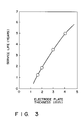
- the service life of the conventional secondary battery having the above structure greatly depends on the thickness of the electrode plate (positive electrode plate). As is well known in the art, when the thickness of the electrode plate is reduced, the service life of the battery is shortened. Taking a conventional lead battery having the above structure as an example, the relationship between the thickness of the electrode plate and the service life under use with a trickle charge is shown in Fig. 3. As is apparent from Fig. 3, the service life of the conventional battery is abruptly shortened when the thickness of the electrode plate is reduced. When the thickness of the electrode plate is 1 mm or less, the battery cannot be repeatedly used as a secondary battery due to the following reason.
- the battery reaction sites generated by charge/discharge extends in a direction perpendicular to the major surface of the electrode plate (i.e., the direction of thickness), as indicated by arrows in Fig. 2.
- a portion which is not associated with the battery reaction i.e., an energy concentration portion must always be present in the electrode.
- the energy concentration portion disappears upon charge/discharge. Therefore, the secondary battery cannot serve as a battery. This situation also occurs when the battery is cyclically used.
- a minimum overall thickness or height of the conventional thin sealed lead battery is 4 to 5 mm.
- an object of the present invention to provide a secondary battery which can be made thin without degrading its performance, and a method of manufacturing the same.
- a secondary battery comprising: positive and negative electrode members arranged on a substantially identical plane, end faces of the positive and negative electrode members opposing each other at a distance; a substrate for fixing and supporting the positive and negative electrode members; a cover member defining, with the substrate, a sealed chamber including the positive and negative electrode members; and an electrolyte sealed in the sealed chamber so as to be present between at least opposite end faces of the positive and negative electrode members, the electrolyte being associated with a battery reaction with the positive and negative electrode members.
- opposed edges of both the electrode members In order to increase the area (i.e., an effective electrode area) of the opposed end faces of both the electrode members, opposed edges of both the electrode members have a wave-like shape (triangular or rectangular shape) or a helical shape when viewed from the top.
- a method of manufacturing a secondary battery comprising the steps of: applying a positive electrode material containing a positive electrode active material and a negative electrode material containing a negative electrode active material to a substrate to form positive and negative electrode members whose end faces oppose each other at a distance; bonding a cover member to the substrate such that the cover member defines, with the substrate, a sealed chamber including the positive and negative electrode members; and filling an electrolyte associated with a battery reaction with the positive and negative electrode members so as to be present between at least the opposite end faces of the positive and negative electrode members.
- a secondary battery according to the present invention has the following characteristic feature.
- Positive and negative electrode members are arranged or juxtaposed on a substantially identical plane unlike the conventional structure wherein the positive and negative electrode members are arranged one above the other in the direction of thickness thereof.
- the end faces of both the electrode members are spaced apart from each other.
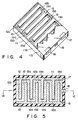
- Figs. 4 to 6 show a secondary battery according to a first embodiment of the present invention.
- interdigital positive and negative electrode members 12 and 13 are formed on one surface of flat substrate 11a.
- Electrolyte 15 associated with or involved in a battery reaction is filled in the space between the positive and negative electrode members 12 and 13.
- Positive electrode member 12 is made of a positive electrode material containing a positive electrode active material
- negative electrode member 13 is made of a negative electrode material containing a negative electrode active material.
- lead dioxide is the positive electrode active material and lead is a negative electrode active material therein.
- a liquid electrolyte such as sulfuric acid is used as electrolyte 15.
- Cover member 11b covers electrode members 12 and 13 and is connected to substrate 11a. Cover member 11b cooperates with substrate 11a to constitute battery case 11 which defines a sealed chamber.
- At least surfaces of substrate 11a and cover member 11b are electrically insulative and may be made of an acid-resistant polymer material (e.g., an acrylonitrile-butadiene-styrene resin (ABS resin) or a fluorine resin), a plastic material, or a glass-fiber reinforced plastic material.
- an acid-resistant polymer material e.g., an acrylonitrile-butadiene-styrene resin (ABS resin) or a fluorine resin
- ABS resin acrylonitrile-butadiene-styrene resin
- fluorine resin fluorine resin
- substrate 11a and cover member 11b may be made of a laminate material obtained by covering a metal layer (e.g., an aluminum layer) with an insulating polymer material, or of a polyvinylidene chloride resin.
- Battery case 11 also has positive and negative terminals 17 and 18, and relief valve 16 which communicates with a space between electrode members 12 and 13.
- positive electrode member 12 has a comb-like shape.
- a plurality of rectangular teeth 12a having a substantially identical shape extend from spine 12b at predetermined intervals.
- Negative electrode member 13 also has a comb-like shape.
- a plurality of rectangular teeth 13a having a substantially identical shape extend from spine 13b at predetermined intervals. Teeth 12a do not contact teeth 13a and constitute an interdigital electrode structure. Thus, the end faces of positive and negative electrode members 12 and 13 oppose each other.
- cover member 11b covers in tight contact with the surfaces of electrode members 12 and 13, so that electrolyte 15 does not enter between cover member 11a and electrode members 12, 13 to contact the upper surfaces of electrode members 12 and 13.
- positive and negative electrodes 12 and 13 are arranged on the surface of substrate 11a, i.e., on an identical plane. As compared with the conventional secondary battery wherein these members are arranged one above the other in the direction of thickness (Figs. 1 and 2), even if the electrode member has the same thickness as that of the conventional battery, the battery thickness can be reduced to about 1/3 that of the conventional battery.
- the extension direction of the sites of the battery reaction during charge/discharge is different from that of the conventional battery.
- the battery of the present invention has the extension direction perpendicular to the direction of thickness of the electrode member (i.e., parallel to the direction of width l of the tooth of the electrodes). For this reason, width l of teeth 12a and 13a (unit electrode) must be assured to be preferably 1-2 mm or more. If this is assured, thickness d of the electrode can be reduced to 1 mm or less, e.g., 0.1 mm in order to assure the same or longer battery service life as or than that of a commercially available conventional thin secondary battery.
- the overall thickness of the secondary battery according to the present invention can be reduced to 1 mm or less.
- substrate 11a is prepared.
- an active material-containing electrode material such as lead paste 72 is applied to substrate 11a by using roller 73 through screen 71 having a predetermined pattern (an interdigital pattern in this case).
- the positive and negative electrode member patterns can be simultaneously formed.
- the thickness of the lead paste is, e.g., 0.1 mm.
- an adhesive may be applied to the surface of substrate 11a in advance or a lead paste containing an adhesive may be used.
- electrolyte solution 15 is injected from electrolyte injection nozzle 74 to a space between positive and negative electrode member patterns 12 and 13.
- the electrolyte may be, e.g., sulfuric acid having a concentration of 30 to 50%, preferably 35 to 45%.
- Cover member 11b having positive and negative terminals 17 and 18 is adhered to substrate 11a by using an adhesive, e.g., an epoxy adhesive.
- Electrolyte 15 may be injected after cover member 11b is bonded to substrate 11a.
- a formation treatment of the electrodes is performed using DC power source 75. This treatment allows conversion of the positive electrode active material into lead dioxide, and conversion of the negative electrode active material into lead. If necessary, the electrolyte may be further injected after the above formation treatment.
- the secondary battery is prepared, and its performance is checked.
- the above formation treatment can be performed prior to mounting of cover member 11b.
- a plurality of substrates 11a shown in Fig. 7C are dipped in a formation treatment sulfuric acid, and the formation treatment can be performed.
- This treatment is suitable for mass production.
- the lead paste is used as both the positive and negative electrode active materials.
- a lead dioxide paste may be used for the positive electrode, and a lead paste may be used for the negative electrode.
- the positive and negative electrode patterns are sequentially formed using separate screens. According to this technique, the above formation treatment may be eliminated, and if so, the process for manufacturing the battery can be simplified. However, even in this case, the formation treatment is preferably conducted to improve the electrode properties.
- the manufacturing process described above can be performed in an automated treatment line.
- Fig. 8 is a longitudinal sectional view of a secondary battery according to a second embodiment of the present invention (thickness d of positive electrode tooth 12a and the negative electrode is emphasized with respect to the width, however, in practice, the thickness is much smaller than width l of teeth 12a and 13a).
- the secondary battery according to the second embodiment is substantially the same as that of the first embodiment except that cover member 11b is separated from the upper surfaces of electrode members 12 and 13.
- its service life is substantially the same as that of the first embodiment.
- the cover member need not be brought into tight contact with the upper surfaces of electrodes 12 and 13, so that the manufacturing process can be simplified.
- the overall thickness of the secondary battery can be reduced to about 1/3 that of the conventional battery.
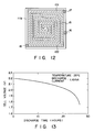
- a lead storage battery having a structure shown in Fig. 8 was manufactured. Dimensions of the battery were 0.65 mm thick, 50 mm wide, and 78 mm long. The weight of the battery was 4.7 g, and its volume was 2.5 cm3. The thickness of each of electrode members 12 and 13 was 0.4 mm. The discharge characteristics of this lead storage battery are shown in Fig. 13. As is apparent from Fig. 13, a discharge curve exhibits voltage changes unique to the lead storage battery as a function of time. The battery capacity was about 40 mAh. The durability of the battery was satisfactory, and the secondary battery of the present invention had characteristics satisfactory for use in practical applications.
- Fig. 9 is a horizontal sectional view of a secondary battery according to a third embodiment of the present invention.
- positive and negative electrode members 91a and 92a opposed to each other at a certain distance constitute one unit cell.
- Positive and negative electrode members 91b and 92b opposed to each other at a certain distance constitute one unit cell, and positive and negative electrode members 91c and 92c opposed to each other at a certain distance constitute one unit cell.
- Thin plate-like positive electrode members 91a to 91c and thin plate-like negative electrode members 92a to 92c are formed on substrate 11a.
- Negative and positive electrode members 92a and 91b are in contact with each other, and negative and positive electrode members 92b and 91c are in contact with each other.
- the secondary battery has a structure in which three unit cells are connected in series with each other.
- the secondary battery having the above structure can obtain a cell voltage of a magnitude three times that of the first embodiment.
- Figs. 10, 11, and 12 are horizontal sectional views of secondary batteries having electrode members of different shapes, respectively.
- each of positive and negative electrode members 101 and 102 is formed in a wave pattern of a substantially sine curve form having a small thickness.
- each of positive and negative electrode members 111 and 112 has a saw-toothed shape (or triangular waveform) having a small thickness.
- each of positive and negative electrode members 121 and 122 has a helical shape having a small thickness.
- the separator need not be used unlike the conventional secondary battery.
- the separator may be arranged as needed. In this case, the separator is arranged between the positive and negative electrode members.
- teeth 12a and 13a of the secondary batteries of the first and second embodiments have a rectangular shape, but may be a zig-zag shape.
- the method of manufacturing a secondary battery according to the present invention is exemplified by screen printing.
- the method of the present invention is not limited thereto.
- Metal flame spraying, plating, deposition, sputtering, ion plating, or plasma CVD, or a combination thereof may be used to form the electrodes.
- the positive plate, the electrolyte, and the negative plate which are the main constituting elements are arranged on a substantially identical plane of the substrate.
- the extension direction of the battery reaction sites during charge/discharge is parallel to the electrode surface. Therefore, the resultant secondary battery has excellent durability and a small thickness.
- the electrode plate is manufactured by a method including screen printing with a screen pattern. Therefore, various batteries can be manufactured by using only the patterns. In addition, the manufacturing process is simple, and great labor and energy saving can be achieved.
Landscapes
- Engineering & Computer Science (AREA)
- Manufacturing & Machinery (AREA)
- Chemical & Material Sciences (AREA)
- Chemical Kinetics & Catalysis (AREA)
- Electrochemistry (AREA)
- General Chemical & Material Sciences (AREA)
- Secondary Cells (AREA)
- Battery Electrode And Active Subsutance (AREA)
Description
- The present invention relates to a secondary battery and a method of manufacturing the same and, more particularly, to a secondary battery which can be made thin without degrading its performance and a method of manufacturing the same.
- Most conventional thin batteries are primary batteries. Typical conventional thin secondary batteries are a thin sealed lead battery and a button type nickel-cadmium battery, which have been recently put on market.
- Referring to Fig. 1 (partially cutaway perspective view) and Fig. 2 (horizontal sectional view), a conventional thin secondary battery has positive and
negative electrodes negative electrode plates battery case 1 such that their major surfaces oppose each other.Separator 4 is interposed betweenelectrodes Electrolyte 5 is filled inbattery case 1.Relief valve 6,positive terminal 7 and negative terminal 8 are provided onbattery case 1. - As described above, the conventional thin secondary battery has a structure wherein
positive electrode plate 2,negative electrode plate 3, andseparator 4 which are the main constituting elements of the battery are positioned one above the other in a direction of thickness thereof. - In order to decrease the height of the battery having the above structure, the thicknesses of positive and
negative electrode plates - The service life of the conventional secondary battery having the above structure greatly depends on the thickness of the electrode plate (positive electrode plate). As is well known in the art, when the thickness of the electrode plate is reduced, the service life of the battery is shortened. Taking a conventional lead battery having the above structure as an example, the relationship between the thickness of the electrode plate and the service life under use with a trickle charge is shown in Fig. 3. As is apparent from Fig. 3, the service life of the conventional battery is abruptly shortened when the thickness of the electrode plate is reduced. When the thickness of the electrode plate is 1 mm or less, the battery cannot be repeatedly used as a secondary battery due to the following reason. In the conventional secondary battery structure, the battery reaction sites generated by charge/discharge extends in a direction perpendicular to the major surface of the electrode plate (i.e., the direction of thickness), as indicated by arrows in Fig. 2. In order to cause any battery to function as a secondary battery, a portion which is not associated with the battery reaction, i.e., an energy concentration portion must always be present in the electrode. When the thickness of the electrode plate is reduced, the energy concentration portion disappears upon charge/discharge. Therefore, the secondary battery cannot serve as a battery. This situation also occurs when the battery is cyclically used.
- Due to the above reasons, a minimum overall thickness or height of the conventional thin sealed lead battery is 4 to 5 mm.
- In order to manufacture the conventional secondary battery, casting, cutting, and rolling of the electrode plates are required, and an active material must be applied to the surface of the electrode plate. Therefore, the manufacturing process is considerably complicated. In addition, according to the conventional method, in order to manufacture batteries having different electrode plate shapes and different battery voltages, different manufacturing lines and individual manufacturing apparatuses are required for manufacturing different batteries. For this reason, it is difficult to satisfy a variety of needs for many types of batteries.
- It is, therefore, an object of the present invention to provide a secondary battery which can be made thin without degrading its performance, and a method of manufacturing the same.
- In order to achieve the above object, there is provided according to an aspect of the present invention a secondary battery, comprising:
positive and negative electrode members arranged on a substantially identical plane, end faces of the positive and negative electrode members opposing each other at a distance;
a substrate for fixing and supporting the positive and negative electrode members;
a cover member defining, with the substrate, a sealed chamber including the positive and negative electrode members; and
an electrolyte sealed in the sealed chamber so as to be present between at least opposite end faces of the positive and negative electrode members, the electrolyte being associated with a battery reaction with the positive and negative electrode members. - In order to increase the area (i.e., an effective electrode area) of the opposed end faces of both the electrode members, opposed edges of both the electrode members have a wave-like shape (triangular or rectangular shape) or a helical shape when viewed from the top.
- According to another aspect of the present invention, there is provided a method of manufacturing a secondary battery comprising the steps of:
applying a positive electrode material containing a positive electrode active material and a negative electrode material containing a negative electrode active material to a substrate to form positive and negative electrode members whose end faces oppose each other at a distance;
bonding a cover member to the substrate such that the cover member defines, with the substrate, a sealed chamber including the positive and negative electrode members; and
filling an electrolyte associated with a battery reaction with the positive and negative electrode members so as to be present between at least the opposite end faces of the positive and negative electrode members. - This invention can be more fully understood from the following detailed description when taken in conjunction with the accompanying drawings, in which:
- Fig. 1 is a partially cutaway perspective view of a conventional thin secondary battery;
- Fig. 2 is a horizontal sectional view of the conventional secondary battery shown in Fig. 1;
- Fig. 3 is a graph showing the relationship between the thickness of the electrode of the conventional secondary battery and the battery service life;
- Fig. 4 is a partially cutaway perspective view of a secondary battery according to a first embodiment of the present invention;
- Fig. 5 is a horizontal sectional view of the secondary battery shown in Fig. 4;
- Fig. 6 is a sectional view of the secondary battery in Fig. 5 along the line VI - VI thereof;
- Figs. 7A to 7E are views for explaining a method of manufacturing the secondary battery according to the present invention;
- Fig. 8 is a longitudinal sectional view of a secondary battery according to a second embodiment of the present invention;
- Fig. 9 is a horizontal sectional view of a secondary battery according to a third embodiment of the present invention;
- Fig. 10 is a horizontal sectional view of a secondary battery according to a fourth embodiment of the present invention;
- Fig. 11 is a horizontal sectional view of a secondary battery according to a fifth embodiment of the present invention;
- Fig. 12 is a horizontal sectional view of a secondary battery according to a sixth embodiment of the present invention; and
- Fig. 13 is a graph showing discharge characteristics of the secondary battery according to the present invention.
- As described above, a secondary battery according to the present invention has the following characteristic feature. Positive and negative electrode members are arranged or juxtaposed on a substantially identical plane unlike the conventional structure wherein the positive and negative electrode members are arranged one above the other in the direction of thickness thereof. The end faces of both the electrode members are spaced apart from each other.
- The present invention will be described in detail with reference to Figs. 4 to 13. The same reference numerals denote the same parts throughout the drawings.
- Figs. 4 to 6 show a secondary battery according to a first embodiment of the present invention. As shown in Fig. 4, interdigital positive and
negative electrode members flat substrate 11a.Electrolyte 15 associated with or involved in a battery reaction is filled in the space between the positive andnegative electrode members -
Positive electrode member 12 is made of a positive electrode material containing a positive electrode active material, andnegative electrode member 13 is made of a negative electrode material containing a negative electrode active material. In a lead battery, lead dioxide is the positive electrode active material and lead is a negative electrode active material therein. A liquid electrolyte such as sulfuric acid is used aselectrolyte 15. -
Cover member 11b coverselectrode members substrate 11a.Cover member 11b cooperates withsubstrate 11a to constitutebattery case 11 which defines a sealed chamber. - At least surfaces of
substrate 11a andcover member 11b are electrically insulative and may be made of an acid-resistant polymer material (e.g., an acrylonitrile-butadiene-styrene resin (ABS resin) or a fluorine resin), a plastic material, or a glass-fiber reinforced plastic material. In order to prevent transmission of water vapor of a liquid electrolyte such as sulfuric acid,substrate 11a andcover member 11b may be made of a laminate material obtained by covering a metal layer (e.g., an aluminum layer) with an insulating polymer material, or of a polyvinylidene chloride resin. -
Battery case 11 also has positive andnegative terminals relief valve 16 which communicates with a space betweenelectrode members - As is best illustrated in Fig. 5,
positive electrode member 12 has a comb-like shape. A plurality ofrectangular teeth 12a having a substantially identical shape extend fromspine 12b at predetermined intervals.Negative electrode member 13 also has a comb-like shape. A plurality ofrectangular teeth 13a having a substantially identical shape extend fromspine 13b at predetermined intervals.Teeth 12a do not contactteeth 13a and constitute an interdigital electrode structure. Thus, the end faces of positive andnegative electrode members - Referring to Fig. 6 (thickness d of each
positive electrode tooth 12a and thenegative electrode tooth 13a is emphasized, however, in practice, thickness d is considerably smaller than width ℓ ofteeth cover member 11b covers in tight contact with the surfaces ofelectrode members electrolyte 15 does not enter betweencover member 11a andelectrode members electrode members - As described above, in the secondary battery of the present invention, positive and
negative electrodes substrate 11a, i.e., on an identical plane. As compared with the conventional secondary battery wherein these members are arranged one above the other in the direction of thickness (Figs. 1 and 2), even if the electrode member has the same thickness as that of the conventional battery, the battery thickness can be reduced to about 1/3 that of the conventional battery. - As indicated by arrows in Fig. 6, in the secondary battery of the present invention, the extension direction of the sites of the battery reaction during charge/discharge is different from that of the conventional battery. The battery of the present invention has the extension direction perpendicular to the direction of thickness of the electrode member (i.e., parallel to the direction of width ℓ of the tooth of the electrodes). For this reason, width ℓ of
teeth - A method of manufacturing the secondary battery according to the present invention as described above by using screen printing will be described with reference to Figs. 7A to 7E.
- As shown in Fig. 7A,
substrate 11a is prepared. - As shown in Fig. 7B, an active material-containing electrode material such as
lead paste 72 is applied tosubstrate 11a by usingroller 73 throughscreen 71 having a predetermined pattern (an interdigital pattern in this case). The positive and negative electrode member patterns can be simultaneously formed. The thickness of the lead paste is, e.g., 0.1 mm. - If a bonding force between the lead paste and
substrate 11a is weak, an adhesive may be applied to the surface ofsubstrate 11a in advance or a lead paste containing an adhesive may be used. - As shown in Fig. 7C,
electrolyte solution 15 is injected fromelectrolyte injection nozzle 74 to a space between positive and negativeelectrode member patterns Cover member 11b having positive andnegative terminals substrate 11a by using an adhesive, e.g., an epoxy adhesive. -
Electrolyte 15 may be injected aftercover member 11b is bonded tosubstrate 11a. - As shown in Fig. 7D, a formation treatment of the electrodes is performed using
DC power source 75. This treatment allows conversion of the positive electrode active material into lead dioxide, and conversion of the negative electrode active material into lead. If necessary, the electrolyte may be further injected after the above formation treatment. - As shown in Fig. 7E, the secondary battery is prepared, and its performance is checked.
- The above formation treatment can be performed prior to mounting of
cover member 11b. In this case, a plurality ofsubstrates 11a shown in Fig. 7C are dipped in a formation treatment sulfuric acid, and the formation treatment can be performed. This treatment is suitable for mass production. - In the above example, the lead paste is used as both the positive and negative electrode active materials. However, a lead dioxide paste may be used for the positive electrode, and a lead paste may be used for the negative electrode. In this case, the positive and negative electrode patterns are sequentially formed using separate screens. According to this technique, the above formation treatment may be eliminated, and if so, the process for manufacturing the battery can be simplified. However, even in this case, the formation treatment is preferably conducted to improve the electrode properties.
- The manufacturing process described above can be performed in an automated treatment line.
- Fig. 8 is a longitudinal sectional view of a secondary battery according to a second embodiment of the present invention (thickness d of
positive electrode tooth 12a and the negative electrode is emphasized with respect to the width, however, in practice, the thickness is much smaller than width ℓ ofteeth cover member 11b is separated from the upper surfaces ofelectrode members electrodes - A lead storage battery having a structure shown in Fig. 8 was manufactured. Dimensions of the battery were 0.65 mm thick, 50 mm wide, and 78 mm long. The weight of the battery was 4.7 g, and its volume was 2.5 cm³. The thickness of each of
electrode members - Fig. 9 is a horizontal sectional view of a secondary battery according to a third embodiment of the present invention. In this secondary battery, positive and
negative electrode members negative electrode members positive electrode members 91a to 91c and thin plate-likenegative electrode members 92a to 92c are formed onsubstrate 11a. Negative andpositive electrode members positive electrode members 92b and 91c are in contact with each other. A battery reaction does not occur betweenmembers members 92b and 91c. The secondary battery has a structure in which three unit cells are connected in series with each other. In addition to the effect of the first embodiment, the secondary battery having the above structure can obtain a cell voltage of a magnitude three times that of the first embodiment. - Figs. 10, 11, and 12 are horizontal sectional views of secondary batteries having electrode members of different shapes, respectively.
- Referring to Fig. 10, each of positive and
negative electrode members - Referring to Fig. 11, each of positive and
negative electrode members - Referring to Fig. 12, each of positive and
negative electrode members - In the secondary battery according to the present invention as has been described above, since the positive and negative electrode members are fixed on the substrate, the separator need not be used unlike the conventional secondary battery. However, the separator may be arranged as needed. In this case, the separator is arranged between the positive and negative electrode members.
- The present invention has been exemplified by the particular embodiments described above but is not limited thereto. For example,
teeth - The method of manufacturing a secondary battery according to the present invention is exemplified by screen printing. However, the method of the present invention is not limited thereto. Metal flame spraying, plating, deposition, sputtering, ion plating, or plasma CVD, or a combination thereof may be used to form the electrodes.
- According to the present invention as has been described above, the positive plate, the electrolyte, and the negative plate which are the main constituting elements are arranged on a substantially identical plane of the substrate. In addition, the extension direction of the battery reaction sites during charge/discharge is parallel to the electrode surface. Therefore, the resultant secondary battery has excellent durability and a small thickness.
- The electrode plate is manufactured by a method including screen printing with a screen pattern. Therefore, various batteries can be manufactured by using only the patterns. In addition, the manufacturing process is simple, and great labor and energy saving can be achieved.
Claims (24)
- A secondary battery comprising positive and negative electrode members (12,13;101,102;111,112;121,122) each having main surfaces and end surfaces, a sealed chamber with a cover member (11b) enclosing the electrode members and an electrolyte, characterized in that
the positive and negative electrode members are arranged on a substantially identical plane, the end faces of the positive and negative electrode members being spaced apart and opposing each other at a distance,
a substrate (11a) fixedly contacting a main surface of the positive and negative electrode members and fixedly supporting the positive and negative electrode members;
the cover member (11b) defining, with the substrate (11a), the sealed chamber enclosing and covering the positive and negative electrode members; and
the electrolyte (15) sealed in the sealed chamber and the cover member being arranged relative to the electrode members such that the electrolyte is substantially present between the opposite end faces of the positive and negative electrode members, the electrolyte being associated with a battery reaction with the positive and negative electrode members, and wherein the electrolyte is present between the end faces of the positive and negative electrode members in an amount sufficient that the battery reaction substantially takes place at battery reaction sites defined between the opposite end faces of the positive and negative electrode members, said battery reaction sites extending substantially perpendicular to the direction of thickness of the positive and negative electrode members wherein the direction of thickness extends perpendicularly to the said main faces. - A battery according to claim 1, characterized in that each of the positive and negative electrode members (12, 13) has a comb-like shape having a plurality of teeth (12a, 13a).
- A battery according to claim 2, characterized in that the tooth (12a, 13a) has a rectangular shape.
- A battery according to claim 1, characterized in that each of the positive and negative electrode members (101, 102; 111, 112) has a wave-like shape.
- A battery according to claim 1, characterized in that each of the positive and negative electrode members has a helical shape (121, 122).
- A battery according to any one of claims 1 to 5, characterized in that
the positive electrode member comprises lead dioxide, the negative electrode member comprises lead, and the electrolyte comprises diluted sulfuric acid. - A battery according to any one of claims 1 to 6, characterized in that each of the positive and negative electrode members (12, 13;...) has a thickness of not more than 1 mm.
- A method of manufacturing a secondary battery which is adapted to be repeatedly subjected to cycles of charging and discharging, comprising the steps of:
applying a positive electrode material containing positive electrode active material and a negative electrode material containing a negative electrode active material to a substrate (11a) to form positive and negative electrode members (12,13;101,102;111,112;121,122) having end faces which oppose each other at a distance, said positive and negative electrode members having main surfaces which are fixed on and juxtaposed on the substrate so as to be supported by the substrate;
bonding a cover member (11b) to the substrate such that the cover member defines, with the substrate, a sealed chamber enclosing and covering the positive and negative electrode members; and
filling an electrolyte (15) associated with a battery reaction with the positive and negative electrode members into said sealed chamber and the cover member being arranged relative to the electrode member such that the electrolyte is substantially present between the opposite end faces of the positive and negative electrode members, the electrolyte being present between the end faces of the positive and negative electrode members in an amount sufficient to produce with the electrode members a battery reaction which substantially takes place at battery reaction sites defined between the opposite end faces of the positive and negative electrode members and said battery reaction sites extending substantially perpendicular to the direction of thickness of the positive and negative electrode members wherein the direction of thickness extends perpendicularly to the said main faces. - A method according to claim 8,
characterized in that
the positive and negative electrode members (12,13;...) are formed on the substrate (11a) by screenprinting metal flame spraying, plating deposition sputtering, ion plating, or plasma chemical vapor deposition. - A method according to claim 8 or 9, characterized in that each of the positive and negative electrode members has a thickness of not more than 1 mm.
- A method according to any one of claims 8 to 10, characterized by further comprising subjecting said positive and negative electrode material applied to said substrate (11a) to a formation treatment.
- A secondary battery device, comprising a plurality of unit cells, a sealed chamber with a cover member enclosing the unit cells and an electrolyte characterised in that the plurality of unit cells are juxtaposed adjacent each other on an identical plane, each unit cell comprising pair of positive and negative electrode members (91a,92a;91b,92b;91c,92c) arranged on said plane, said positive and negative electrode members each having end faces opposing each other at a distance, the positive electrode member of one unit cell and the negative electrode member of another unit cell in each adjacent two unit cells contacting with each other at respective end faces;
a substrate fixedly contacting a main surface of said positive and negative electrode members and fixedly supporting said electrode members of said plurality of unit cells;
the cover member defining, with said substrate, the sealed chamber enclosing and covering said plurality of unit cells; and
the electrolyte (15) sealed in said sealed chamber, and the cover member being arranged relative to the electrode members such that the electrolyte is substantially present between the opposite end faces of the positive and negative electrode members of each unit cell, the electrolyte being present between the end faces of the positive and negative electrode members in an amount sufficient to produce a battery reaction with the positive and negative electrode members of each unit cell, which battery reaction substantially takes place at battery reaction sites defined between opposite end faces of the positive and negative electrode members and said battery reaction sites extending substantially perpendicular to the direction of thickness of the positive and negative electrode members wherein the direction of thickness extends perpendicularly to the said main faces. - A device according to claim 12, characterised in that each of the positive and negative electrode members (12,13;12a,13a) as a comb-like shape having a plurality of teeth.
- A device according to claim 13, characterised in that said teeth of said comb-like shaped electrode members has a substantially rectangular shape.
- A device according to claim 12, characterised in that each of the positive and negative electrode members (101,102) has a wave-like shape.
- A device according to claim 12, characterised in that each of the positive and negative electrode members (121,122) has a helical shape.
- A device according to anyone of claims 12 to 16, characterised in that the positive electrode member comprises lead dioxide, the negative electrode member comprises lead, and the electrolyte comprises diluted sulfuric acid.
- A device according to anyone of claims 12 to 17, characterised in that each of the positive and negative electrode members has a thickness of not more than 1 mm.
- A device according anyone of claims 12 to 18, characterised in that substantially all of said electrolyte is present between the opposite end faces of the positive and negative electrode members.
- A device according to anyone of claims 12 to 19, characterised in that said cover member contacts main surfaces of said positive and negative electrode members which are opposite to those main surfaces which contact said substrate, whereby all of the electrolyte is between the opposite end faces of the electrode members, the electrolyte not contacting main surfaces of the positive and negative electrode members.
- A battery according to anyone of claims 1 to 7, characterised in that substantially all of said electrolyte is present between the opposite end faces of the positive and negative electrode members.
- A battery according to anyone of claims 1 to 7 and 21, characterised in that said cover member contacts main surfaces of said positive and negative electrode members which are opposite to those main surfaces which contact said substrate, whereby all of the electrolyte is between the opposite end faces of the electrode members, the electrolyte not contacting main surfaces of the positive and negative electrode members.
- A method according to anyone of claims 8 to 11, characterised in that said step of filling said electrolyte comprises filling substantially all of said electrolyte in spaces between the opposite end faces of the positive and negative electrode members.
- A method according to anyone of claims 8 to 11 and 23, characterised in that the step of bonding the cover member to the substrate comprises contacting the cover member with main surfaces of the positive and negative electrode members are opposite from those main surfaces contacting the substrate, such that the electrolyte is filled in said chamber, all of the electrolyte is present in the spaces between end faces of the positive and negative electrode members, and no electrolyte contacts the main surface which are contacted by the cover member.
Applications Claiming Priority (2)
| Application Number | Priority Date | Filing Date | Title |
|---|---|---|---|
| JP19641587 | 1987-08-07 | ||
| JP196415/87 | 1987-08-07 |
Publications (2)
| Publication Number | Publication Date |
|---|---|
| EP0302520A1 EP0302520A1 (en) | 1989-02-08 |
| EP0302520B1 true EP0302520B1 (en) | 1992-11-25 |
Family
ID=16357476
Family Applications (1)
| Application Number | Title | Priority Date | Filing Date |
|---|---|---|---|
| EP88112803A Expired - Lifetime EP0302520B1 (en) | 1987-08-07 | 1988-08-05 | Secondary battery and method of manufacturing the same |
Country Status (6)
| Country | Link |
|---|---|
| US (1) | US4889777A (en) |
| EP (1) | EP0302520B1 (en) |
| JP (1) | JPH0690934B2 (en) |
| KR (1) | KR920005187B1 (en) |
| CA (1) | CA1294670C (en) |
| DE (1) | DE3876166T2 (en) |
Families Citing this family (68)
| Publication number | Priority date | Publication date | Assignee | Title |
|---|---|---|---|---|
| US5619117A (en) * | 1982-06-07 | 1997-04-08 | Norand Corporation | Battery pack having memory |
| CA2410721C (en) * | 1989-06-14 | 2006-04-04 | Gp Batteries International Limited | Ultra-thin plate electrochemical cell and method of manufacture |
| JPH0754714B2 (en) * | 1990-11-21 | 1995-06-07 | 日本電信電話株式会社 | Thin lead acid battery and manufacturing method thereof |
| US5219673A (en) * | 1991-08-23 | 1993-06-15 | Kaun Thomas D | Cell structure for electrochemical devices and method of making same |
| JPH05129036A (en) * | 1991-11-06 | 1993-05-25 | Shin Kobe Electric Mach Co Ltd | Sealed secondary battery |
| FR2694136B1 (en) * | 1992-07-27 | 1994-09-30 | Bertin & Cie | Electric storage battery equipped with cooling means and set of such batteries. |
| US6063520A (en) * | 1996-04-12 | 2000-05-16 | Mitsubishi Chemical Corporation | Lightweight battery container and method for fabrication of same |
| US6040078A (en) * | 1997-03-06 | 2000-03-21 | Mitsubishi Chemical Corporation | Free form battery apparatus |
| US6224995B1 (en) | 1997-03-06 | 2001-05-01 | Mitsubishi Chemical Corporation | Three dimensional free form battery apparatus |
| US6045942A (en) * | 1997-12-15 | 2000-04-04 | Avery Dennison Corporation | Low profile battery and method of making same |
| US7662265B2 (en) * | 2000-10-20 | 2010-02-16 | Massachusetts Institute Of Technology | Electrophoretic assembly of electrochemical devices |
| KR101249133B1 (en) * | 2000-10-20 | 2013-04-02 | 매사츄세츠 인스티튜트 오브 테크놀러지 | Bipolar device |
| US7387851B2 (en) | 2001-07-27 | 2008-06-17 | A123 Systems, Inc. | Self-organizing battery structure with electrode particles that exert a repelling force on the opposite electrode |
| WO2003012908A2 (en) | 2001-07-27 | 2003-02-13 | Massachusetts Institute Of Technology | Battery structures, self-organizing structures and related methods |
| US7820320B2 (en) | 2001-08-20 | 2010-10-26 | Power Paper Ltd. | Method of making a thin layer electrochemical cell with self-formed separator |
| US7491465B2 (en) * | 2004-03-23 | 2009-02-17 | Power Paper, Ltd. | Method of making a thin layer electrochemical cell with self-formed separator |
| KR101209358B1 (en) * | 2001-12-21 | 2012-12-07 | 메사추세츠 인스티튜트 오브 테크놀로지 | Conductive lithium storage electrode |
| US7087348B2 (en) * | 2002-07-26 | 2006-08-08 | A123 Systems, Inc. | Coated electrode particles for composite electrodes and electrochemical cells |
| WO2004012286A1 (en) | 2002-07-26 | 2004-02-05 | A123 Systems, Inc. | Bipolar articles and related methods |
| US6986199B2 (en) * | 2003-06-11 | 2006-01-17 | The United States Of America As Represented By The Secretary Of The Navy | Laser-based technique for producing and embedding electrochemical cells and electronic components directly into circuit board materials |
| US7318982B2 (en) * | 2003-06-23 | 2008-01-15 | A123 Systems, Inc. | Polymer composition for encapsulation of electrode particles |
| DE10328316A1 (en) | 2003-06-23 | 2005-01-20 | Grünenthal GmbH | Process for the preparation of dimethyl (3-aryl-butyl) -amine compounds as pharmaceutical active ingredients |
| TWI244789B (en) * | 2003-08-01 | 2005-12-01 | Hon Hai Prec Ind Co Ltd | A battery and make same |
| JP4920169B2 (en) * | 2003-10-06 | 2012-04-18 | 日産自動車株式会社 | Battery and vehicle equipped with this battery |
| JP4581384B2 (en) * | 2003-12-08 | 2010-11-17 | 日産自動車株式会社 | Battery and manufacturing method thereof |
| JP4645039B2 (en) * | 2004-02-02 | 2011-03-09 | 新神戸電機株式会社 | Manufacturing method of cylindrical sealed lead-acid battery |
| US8722235B2 (en) | 2004-04-21 | 2014-05-13 | Blue Spark Technologies, Inc. | Thin printable flexible electrochemical cell and method of making the same |
| US7794510B1 (en) * | 2004-11-12 | 2010-09-14 | National Semiconductor Corporation | On chip battery |
| JP2006147210A (en) * | 2004-11-17 | 2006-06-08 | Hitachi Ltd | Secondary battery and manufacturing method thereof |
| US7842420B2 (en) | 2005-02-03 | 2010-11-30 | A123 Systems, Inc. | Electrode material with enhanced ionic transport properties |
| US8029927B2 (en) | 2005-03-22 | 2011-10-04 | Blue Spark Technologies, Inc. | Thin printable electrochemical cell utilizing a “picture frame” and methods of making the same |
| US8722233B2 (en) | 2005-05-06 | 2014-05-13 | Blue Spark Technologies, Inc. | RFID antenna-battery assembly and the method to make the same |
| DE102005052588A1 (en) | 2005-11-02 | 2007-05-10 | Grünenthal GmbH | Process for the preparation of substituted dimethyl- (3-aryl-butyl) -amine compounds by means of homogeneous catalysis |
| JP5167584B2 (en) * | 2005-12-01 | 2013-03-21 | 日本電気株式会社 | Non-aqueous electrolyte secondary battery |
| TWI496762B (en) | 2006-07-24 | 2015-08-21 | Method for preparing (1R,2R)-3-(3-dimethylamino-1-ethyl-2-methyl-propyl)-phenol | |
| MX2009006671A (en) * | 2006-12-21 | 2009-07-10 | Jan Petrus Human | Electrical storage device. |
| JP2010524164A (en) * | 2007-04-02 | 2010-07-15 | コーニンクレッカ フィリップス エレクトロニクス エヌ ヴィ | Electrochemical energy source and electronic device having such an electrochemical energy source |
| US20090202903A1 (en) | 2007-05-25 | 2009-08-13 | Massachusetts Institute Of Technology | Batteries and electrodes for use thereof |
| JP5104066B2 (en) * | 2007-06-29 | 2012-12-19 | 住友電気工業株式会社 | battery |
| JP2009021148A (en) * | 2007-07-13 | 2009-01-29 | Someya Densen Kk | Wire connection structure |
| CN101802848A (en) * | 2007-07-18 | 2010-08-11 | 蓝色火花科技有限公司 | Integrated electronic device and methods of making the same |
| US8574754B2 (en) * | 2007-12-19 | 2013-11-05 | Blue Spark Technologies, Inc. | High current thin electrochemical cell and methods of making the same |
| EP2406793B1 (en) * | 2009-03-12 | 2016-11-09 | The Curators Of The University Of Missouri | High energy-density radioisotope micro power sources |
| JP5115591B2 (en) * | 2010-06-10 | 2013-01-09 | 株式会社デンソー | Battery electrode stack |
| JP5639804B2 (en) * | 2010-07-13 | 2014-12-10 | 株式会社Screenホールディングス | Battery manufacturing method, battery, vehicle, and electronic device |
| US9065093B2 (en) | 2011-04-07 | 2015-06-23 | Massachusetts Institute Of Technology | Controlled porosity in electrodes |
| WO2013044224A2 (en) | 2011-09-22 | 2013-03-28 | Blue Spark Technologies, Inc. | Cell attachment method |
| GB201203713D0 (en) | 2012-03-02 | 2012-04-18 | Energy Diagnostic Ltd | Energy storage battery |
| US8765284B2 (en) | 2012-05-21 | 2014-07-01 | Blue Spark Technologies, Inc. | Multi-cell battery |
| KR20240055130A (en) | 2012-08-16 | 2024-04-26 | 에노빅스 코오퍼레이션 | Electrode structures for three-dimensional batteries |
| WO2014070254A1 (en) | 2012-11-01 | 2014-05-08 | Blue Spark Technologies, Inc. | Body temperature logging patch |
| WO2014085604A1 (en) | 2012-11-27 | 2014-06-05 | Blue Spark Technologies, Inc. | Battery cell construction |
| CN105308772B (en) * | 2013-03-15 | 2018-11-16 | 艾诺维克斯公司 | Separator for three-dimensional battery |
| JP5737313B2 (en) * | 2013-03-28 | 2015-06-17 | Tdk株式会社 | Electronic component and manufacturing method thereof |
| FR3007207B1 (en) * | 2013-06-12 | 2016-09-02 | Commissariat Energie Atomique | SECONDARY BATTERY PLANE |
| EP3012897B1 (en) * | 2013-06-21 | 2017-11-29 | Tokyo Ohka Kogyo Co., Ltd. | Nonaqueous secondary battery and method for manufacturing same |
| US10569480B2 (en) | 2014-10-03 | 2020-02-25 | Massachusetts Institute Of Technology | Pore orientation using magnetic fields |
| US10675819B2 (en) | 2014-10-03 | 2020-06-09 | Massachusetts Institute Of Technology | Magnetic field alignment of emulsions to produce porous articles |
| US9693689B2 (en) | 2014-12-31 | 2017-07-04 | Blue Spark Technologies, Inc. | Body temperature logging patch |
| TWI793480B (en) | 2015-05-14 | 2023-02-21 | 美商易諾維公司 | Longitudinal constraints for energy storage devices |
| TWI739830B (en) | 2016-05-13 | 2021-09-21 | 美商易諾維公司 | Dimensional constraints for three-dimensional batteries |
| TWI819481B (en) | 2016-11-16 | 2023-10-21 | 美商易諾維公司 | Three-dimensional batteries with compressible cathodes |
| US10849501B2 (en) | 2017-08-09 | 2020-12-01 | Blue Spark Technologies, Inc. | Body temperature logging patch |
| KR102859540B1 (en) | 2017-11-15 | 2025-09-17 | 에노빅스 코오퍼레이션 | Electrode assembly and secondary battery |
| US10256507B1 (en) | 2017-11-15 | 2019-04-09 | Enovix Corporation | Constrained electrode assembly |
| US11211639B2 (en) | 2018-08-06 | 2021-12-28 | Enovix Corporation | Electrode assembly manufacture and device |
| JP7844451B2 (en) | 2020-09-18 | 2026-04-13 | エノビクス・コーポレイション | Manufacturing of electrodes used in batteries |
| CN116783744A (en) | 2020-12-09 | 2023-09-19 | 艾诺维克斯公司 | Method and device for manufacturing electrode assembly of secondary battery |
Citations (1)
| Publication number | Priority date | Publication date | Assignee | Title |
|---|---|---|---|---|
| WO1987004011A1 (en) * | 1985-12-19 | 1987-07-02 | Neste Oy | Storage battery |
Family Cites Families (8)
| Publication number | Priority date | Publication date | Assignee | Title |
|---|---|---|---|---|
| US629325A (en) * | 1897-07-29 | 1899-07-25 | Electric Power Dev Co | Secondary battery. |
| US629372A (en) * | 1898-08-29 | 1899-07-25 | Electric Power Dev Co | Storage battery. |
| DE2444691A1 (en) * | 1974-09-18 | 1976-04-01 | Rhein Westfael Elect Werk Ag | PROCESS FOR THE PRODUCTION OF ELECTRODES BUILT UP FROM TITANIUM CARRIER AND LEAD DIOXIDE PAD FOR ELECTROLYTIC PURPOSES |
| GB1533116A (en) * | 1975-02-21 | 1978-11-22 | Chloride Group Ltd | Electric batteries |
| US4098965A (en) * | 1977-01-24 | 1978-07-04 | Polaroid Corporation | Flat batteries and method of making the same |
| JPS58133769A (en) * | 1982-02-03 | 1983-08-09 | Toppan Printing Co Ltd | Plate-like battery |
| FR2544134A1 (en) * | 1983-04-08 | 1984-10-12 | Europ Accumulateurs | Method of manufacturing an electrode for an electrochemical generator, electrode thus obtained and applications |
| JPS59228353A (en) * | 1983-06-08 | 1984-12-21 | Matsushita Electric Ind Co Ltd | flat battery |
-
1988
- 1988-07-25 JP JP63185085A patent/JPH0690934B2/en not_active Expired - Fee Related
- 1988-07-27 KR KR8809493A patent/KR920005187B1/en not_active Expired
- 1988-08-02 US US07/227,370 patent/US4889777A/en not_active Expired - Lifetime
- 1988-08-05 CA CA000573977A patent/CA1294670C/en not_active Expired - Lifetime
- 1988-08-05 EP EP88112803A patent/EP0302520B1/en not_active Expired - Lifetime
- 1988-08-05 DE DE8888112803T patent/DE3876166T2/en not_active Expired - Lifetime
Patent Citations (1)
| Publication number | Priority date | Publication date | Assignee | Title |
|---|---|---|---|---|
| WO1987004011A1 (en) * | 1985-12-19 | 1987-07-02 | Neste Oy | Storage battery |
Also Published As
| Publication number | Publication date |
|---|---|
| US4889777A (en) | 1989-12-26 |
| CA1294670C (en) | 1992-01-21 |
| JPH01132064A (en) | 1989-05-24 |
| KR920005187B1 (en) | 1992-06-29 |
| KR890004462A (en) | 1989-04-22 |
| DE3876166D1 (en) | 1993-01-07 |
| EP0302520A1 (en) | 1989-02-08 |
| DE3876166T2 (en) | 1993-06-17 |
| JPH0690934B2 (en) | 1994-11-14 |
Similar Documents
| Publication | Publication Date | Title |
|---|---|---|
| EP0302520B1 (en) | Secondary battery and method of manufacturing the same | |
| US12347821B2 (en) | Dimensional constraints for three-dimensional batteries | |
| US11600864B2 (en) | Constrained electrode assembly | |
| US5047300A (en) | Ultra-thin plate electrochemical cell | |
| EP1318561A1 (en) | Coin-shaped battery | |
| KR100622199B1 (en) | Electrical rechargeable battery in the form of a button cell | |
| US5705259A (en) | Method of using a bipolar electrochemical storage device | |
| EP0512417B1 (en) | Zinc secondary battery having bipolar plate construction with horizontally disposed battery components | |
| CA2333017C (en) | Electrochemical battery structure and method | |
| CA2177056A1 (en) | A solid state battery using an ionic or protonic electrolyte | |
| EP1497874B1 (en) | Battery with vibration-resistant joint between positive electrode and current carrying strap | |
| JPH04294071A (en) | Li battery | |
| JPH0773871A (en) | Bipolar plate for lead acid battery | |
| US6103417A (en) | Flat elementary electrochemical cell and precursor element | |
| US4194060A (en) | Electric accumulator and storage cell | |
| US4683648A (en) | Lead-titanium, bipolar electrode in a lead-acid battery | |
| JPS62165875A (en) | Storage battery | |
| US20220223986A1 (en) | Cell battery | |
| JPS62165876A (en) | Storage battery | |
| US4204034A (en) | Electrochemical cell | |
| US12620613B2 (en) | Dimensional constraints for three-dimensional batteries | |
| JP2773208B2 (en) | Manufacturing method of thin storage battery | |
| JPH05217574A (en) | Electrode plate group for lead-acid battery | |
| JPH0447665A (en) | Square cell | |
| CN117242597A (en) | Bipolar battery panels and their manufacture |
Legal Events
| Date | Code | Title | Description |
|---|---|---|---|
| PUAI | Public reference made under article 153(3) epc to a published international application that has entered the european phase |
Free format text: ORIGINAL CODE: 0009012 |
|
| 17P | Request for examination filed |
Effective date: 19880805 |
|
| AK | Designated contracting states |
Kind code of ref document: A1 Designated state(s): DE FR GB SE |
|
| 17Q | First examination report despatched |
Effective date: 19910219 |
|
| GRAA | (expected) grant |
Free format text: ORIGINAL CODE: 0009210 |
|
| AK | Designated contracting states |
Kind code of ref document: B1 Designated state(s): DE FR GB SE |
|
| ET | Fr: translation filed | ||
| REF | Corresponds to: |
Ref document number: 3876166 Country of ref document: DE Date of ref document: 19930107 |
|
| PLBE | No opposition filed within time limit |
Free format text: ORIGINAL CODE: 0009261 |
|
| STAA | Information on the status of an ep patent application or granted ep patent |
Free format text: STATUS: NO OPPOSITION FILED WITHIN TIME LIMIT |
|
| 26N | No opposition filed | ||
| EAL | Se: european patent in force in sweden |
Ref document number: 88112803.7 |
|
| REG | Reference to a national code |
Ref country code: FR Ref legal event code: CA |
|
| REG | Reference to a national code |
Ref country code: GB Ref legal event code: IF02 |
|
| PGFP | Annual fee paid to national office [announced via postgrant information from national office to epo] |
Ref country code: GB Payment date: 20070801 Year of fee payment: 20 |
|
| PGFP | Annual fee paid to national office [announced via postgrant information from national office to epo] |
Ref country code: DE Payment date: 20071030 Year of fee payment: 20 Ref country code: SE Payment date: 20070817 Year of fee payment: 20 |
|
| PGFP | Annual fee paid to national office [announced via postgrant information from national office to epo] |
Ref country code: FR Payment date: 20070718 Year of fee payment: 20 |
|
| REG | Reference to a national code |
Ref country code: GB Ref legal event code: PE20 Expiry date: 20080804 |
|
| EUG | Se: european patent has lapsed | ||
| PG25 | Lapsed in a contracting state [announced via postgrant information from national office to epo] |
Ref country code: GB Free format text: LAPSE BECAUSE OF EXPIRATION OF PROTECTION Effective date: 20080804 |