EP0302559B1 - Machine à traire - Google Patents
Machine à traire Download PDFInfo
- Publication number
- EP0302559B1 EP0302559B1 EP88201616A EP88201616A EP0302559B1 EP 0302559 B1 EP0302559 B1 EP 0302559B1 EP 88201616 A EP88201616 A EP 88201616A EP 88201616 A EP88201616 A EP 88201616A EP 0302559 B1 EP0302559 B1 EP 0302559B1
- Authority
- EP
- European Patent Office
- Prior art keywords
- carrier
- teat cup
- carriage
- right angles
- machine according
- Prior art date
- Legal status (The legal status is an assumption and is not a legal conclusion. Google has not performed a legal analysis and makes no representation as to the accuracy of the status listed.)
- Expired - Lifetime
Links
- 241001465754 Metazoa Species 0.000 claims description 22
- 210000000481 breast Anatomy 0.000 claims description 8
- 230000000063 preceeding effect Effects 0.000 claims 1
- 210000002445 nipple Anatomy 0.000 description 25
- 238000010276 construction Methods 0.000 description 4
- 230000006978 adaptation Effects 0.000 description 1
- 230000003670 easy-to-clean Effects 0.000 description 1
- 239000000463 material Substances 0.000 description 1
- 239000008267 milk Substances 0.000 description 1
- 210000004080 milk Anatomy 0.000 description 1
- 235000013336 milk Nutrition 0.000 description 1
Images
Classifications
-
- A—HUMAN NECESSITIES
- A01—AGRICULTURE; FORESTRY; ANIMAL HUSBANDRY; HUNTING; TRAPPING; FISHING
- A01J—MANUFACTURE OF DAIRY PRODUCTS
- A01J5/00—Milking machines or devices
- A01J5/017—Automatic attaching or detaching of clusters
- A01J5/0175—Attaching of clusters
Definitions
- the invention relates to a machine for milking animals, comprising a mobile carrier for taking a number of teat cups under an udder of an animal to be milked, said carrier being carried by a supporting structure supported on the fixed surrounding area and bearing on both sides one or more carriages which are approximately horizontally movably guided by said carrier in its lenghtwise direction, each carriage being provided with a teat cup holder which carries a teat cup and which is approximately horizontally movably guided along guiding means, from and to the carrier.
- Such machines are known from WO-A-85 02973.
- the individual teat cups are supported resiliently in a slide which can move in one horizontal direction through being supported by another slide which can move in a horizontal direction at right angles to the said direction on said common carrier, so that the teat cups can be adjusted in two directions at right angles to each other, for example under the influence of a computer memory containing data on the teat positions of each individual animal to be milked.
- the common carrier can pivot freely about a horizontal axis at right angles to the lengthwise direction of the animal, and can be held pressed upwards with a constant force while the teat cups are connected.
- the teat cups have wide top parts also holding the bottom part of the udder.
- Said known milking machine pivots from the rear end of the animal between the hind legs through to below the udder.
- the object of the invention is to improve such known designs, particularly in construction, in such a way that with a relatively simple construction which takes up little space and is easy to inspect and repair, optimum adaptation of the position of the teat cups to each individual animal is easily possible.
- a milking machine of the type referred to in the preamble is according to the invention characterized in that the common carrier is a narrow oblong element with its lengthwise direction in the lengthwise direction of and in the lengthwise centre of the animal to be milked, and in that each carriage carries two approximately vertical linear motors such as pneumatic cylinders, one of which by means of a lever mechanism moves the teat cup holder relative to the carriage approximately horizontally at right angles to the common carrier, while the other handles vertical movement of the teat cup holder together with said guiding means.
- the common carrier is a narrow oblong element with its lengthwise direction in the lengthwise direction of and in the lengthwise centre of the animal to be milked
- each carriage carries two approximately vertical linear motors such as pneumatic cylinders, one of which by means of a lever mechanism moves the teat cup holder relative to the carriage approximately horizontally at right angles to the common carrier, while the other handles vertical movement of the teat cup holder together with said guiding means.
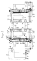
- a common carrier 1 for the teat cups 2 is designed as a vertical long plate having on the top and bottom end two upright strips 3 projecting upwards and downwards from the plate.
- Each carriage 4 bears at its bottom end a horizontal double-acting pneumatic cylinder 6 having a supply and discharge line (not shown), and having a piston rod 7 which is fixed to an arm 8 on the carrier 1.
- a fixed rod 9 on said carrier 1 runs parallel to said piston rod 7 and engages in the lengthwise direction in relatively mobile fashion in a box 10 on the carriage.
- Said parts 9 and 10 carry position-determining means (not shown), for example a number of LEDs on one of said parts (normally on box 10) and a photosensor on the other part, With electrical cables (not shown), all this in order to determine in a manner which is known per se the position of each carriage 4 along the carrier 1 and to stop the movement of the carriage when it has reached a position on the carrier determined by a computer.
- position-determining means for example a number of LEDs on one of said parts (normally on box 10) and a photosensor on the other part.
- An upright pneumatic cylinder 11 is disposed on each carriage 4, and a vertically movable part thereof (the cylinder or the piston rod as desired) is fixed on a lifting plate 12 which is movable vertically relative to the carriage.
- Said plate has a welded-on vertical cross plate 12'.
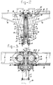
- the lifting plate 12 can be guided up and down relative to the carriage by means of rollers 13 which are disposed on the arm and which engage with flanges round inwardly displaced side edges 14 of the carriage, for example two rollers 13 on each side of each carriage.
- the flanges of the rollers 13 can be seen in Fig. 2.
- the cylinders 11 are designed and fed in such a way that they can move their lifting plate 12 up with an elastic force, i.e. said movement stops when the teat cup 2 carried by the lifting plate meets with a certain settable resistance from the udder and/or teat of the cow, the pressure in the cylinder 11 in question being held at that value during milking.
- Each lifting plate 12 has two parallel horizontal bars 15, projecting at right angles from the carrier 1 and supported by slanting struts 16.
- Each teat cup 2 hangs in a Cardan ring 17 with a horizontal hinge pin 18 between cup and ring and a horizontal hinge pin 19 between said ring and a teat cup holder 20, with a relatively long slide bush 21 slidingly supported on one of the bars 15, or two shorter slide bushes 21, one on each of the bars 15.
- a bar link system 22, 23 is hingedly connected by the bottom end 24 of the double long bar 22 to the moving part of a vertical pneumatic cylinder 25 accommodated in the lifting plate, and by the top end of said bar 22 to the holder 20 at 26.
- the cylinder 25 is next to the cylinder 11 carried by the carriage and has at the bottom end of its moving part a slide block 25' which is guided in a vertical groove between the vertical main face of lifting plate 12 and the cross plate 12' thereon.
- the short bar 23 is hingedly connected at one side to a point near the centre of bar 22 (engaging between the two bars 22) and at the other to a fixed point 27 on the lifting plate.
- the cross plate 12' on plate 12 forms a lateral guide for and between the two bars 22 (Fig. 1).
- the holder 20 thereby moves sideways with the Cardan ring 17 and the teat cup 2, while the bush 21 slides along the bar 15.
- a distance measuring and indicator system for example with LEDs and a photosensor movable along them, all these being as known per se, and being only shown schematically here at the top lefthand side of Fig. 1 and on the righthand side of Figs. 2 and 3, as a box 28, in which an upright part 20' on the holder 20 engages and slides therein.
- the upright carrier 1 is hingedly supported at 29 (Fig. 1) by a supporting structure 30, which is not shown in further detail, and which can, for example in a manner such as that indicated in the above-mentioned WO-A-85 02973, take said carrier forward from the rear end of an animal for milking between the hind legs through to below the udder, and can move it up and down to connect and remove the milking machine.
- a supporting structure 30 which is not shown in further detail, and which can, for example in a manner such as that indicated in the above-mentioned WO-A-85 02973, take said carrier forward from the rear end of an animal for milking between the hind legs through to below the udder, and can move it up and down to connect and remove the milking machine.
- the carrier hangs with the teat cups pivoting freely about a horizontal transverse shaft near the centre in a supporting structure.
- the carrier 1 should not be left to seek its own position through the resistance met with from teats and udder, but that the data on the difference in height between the front and rear teats of a particular animal should also be stored in a computer memory together with other data on the teat positions and the individual milking behaviour thereof, so that on recognition of a particular animal through an identification means worn by it, not only are the carriages and arms taken into the correct horizontal positions for that animal, as described, but the carrier 1 is also turned in a position adapted to that animal about hinge pin 29 to take up either a horizontal position or a position differing from that.
- a pneumatic cylinder 31 with piston rod 32 is provided between the supporting structure 30 and the carrier 1, at a distance from hinge pin 29, and pivoting at 33 and 34.
- a position measuring and setting device 35 between the moving parts for example again with LEDs and a photosensor.
- the supporting structure 30, although movable until it is below the animal and up and down relative thereto, is always held in the same angular position in a vertical plane by means of a parallel construction not shown, so that the change in the length of cylinder 31 and piston rod 32 is a direct measure of the angular position of carrier 1 relative to the horizontal.
- the teat cups 2 can be designed in any desired way, and in the usual manner are provided with flexible linings, a connection 36 for pulsating pressure between rigid casing and lining, a milk discharge line etc., which need not be shown in further detail here.
- each teat cup can be taken quickly to the correct position for each animal for milking, in two horizontal directions at right angles to each other, the positions being determined and fed from a computer memory after recognition of the animal to be milked, while the carrier 1 can be taken into the desired horizontal position, or a position differing therefrom, and the teat cups are held individually by an elastic upward pressure during milking.
Landscapes
- Life Sciences & Earth Sciences (AREA)
- Animal Husbandry (AREA)
- Environmental Sciences (AREA)
- Ink Jet (AREA)
- Dairy Products (AREA)
- External Artificial Organs (AREA)
- Automatic Analysis And Handling Materials Therefor (AREA)
Claims (6)
- Machine à traire des animaux comportant un support mobile (1) pour acheminer une pluralité de gobelets trayeurs (2) sous une mamelle d'un animal à traire, ledit support étant porté par une structure support (30) montée sur la structure fixe environnante et portant sur les deux côtés un ou plusieurs chariots (4) qui sont guidés de façon déplaçable approximativement horizontalement par ledit support (1) dans son sens longitudinal, chaque chariot (4) étant muni d'un support (20) de gobelet trayeur qui porte un gobelet trayeur (2) et qui est guidé de façon déplaçable approximativement horizontalement, le long de moyens de guidage (15), depuis et vers le support (1), caractérisée en ce que le support (1) est un élément oblong étroit avec son sens longitudinal dans le sens longitudinal de et dans l'axe longitudinal de l'animal à traire, et en ce que chaque chariot (4) porte deux moteurs linéaires approximativement verticaux, tels que des vérins pneumatiques, dont l'un (25) déplace, au moyen d'un mécanisme à leviers (22, 23), le support (20) de gobelet trayeur par rapport au chariot (4) approximativement horizontalement orthogonalement au support commun (1), tandis que l'autre (11) assure le mouvement vertical du support (20) de gobelet trayeurs conjointement avec lesdits moyens de guidage (15).
- Machine selon la revendication 1, dans laquelle les deux moteurs linéaires (11, 25) se trouvent dans le même plan vertical, orhogonalement au sens de déplacement du chariot (4).
- Machine selon la revendication 1, dans laquelle le support (1) est relié à ladite structure support (30), de telle manière qu'il pivote autour d'un axe approximativement horizontal (29), orhtogonalement au sens longitudinal du support (1), et un mécanisme d'inclinaison (31, 32) est disposé entre eux pour déplacer ledit support (1) en position angulaire dans et hors de la position horizontale et pour le maintenir dans une position désirée quelconque ainsi obtenue.
- Machine selon la revendication 1, 2 ou 3, dans laquelle le support (20) de gobelet trayeur possède une structure (17) d'anneau à la Cardan, au moyen de laquelle il porte son gobelet trayeur (2), de sorte qu'il peut être orienté de tous côtés.
- Machine selon l'une quelconque des revendications précédentes, dans laquelle des éléments de télécommande (9, 10, 28) sont disposés entre le support (1) et les chariots (4) et entre les supports (20) de gobelets trayeurs et les chariots (4), afin de déterminer le mouvement de chaque support (20) de gobelets trayeurs dans son chariot (4) orthogonalement au support (1), et pour les arrêter, sous la commande d'un calculateur, lorsque la partie mobile pertinente atteint la position correcte, de sorte que chaque gobelet trayeur est placé dans la position correcte dans deux directions horizontales orthogonales entre elles, approprieé pour un animal particulier à traire.
- Machine selon l'une quelconque des revendications précédentes, dans laquelle des éléments de commande de distance ou d'angle (35) sont prévus près de ou sur le mécanisme d'inclinaison (31, 32) entre le support (1) et la structure support (30), afin d'interrompre le mouvement d'inclinaison du support (1) sous la commande d'un calculateur lorsque la position inclinée correcte pour un animal particulier à traire est atteinte.
Applications Claiming Priority (2)
| Application Number | Priority Date | Filing Date | Title |
|---|---|---|---|
| NL8701848 | 1987-08-05 | ||
| NL8701848A NL8701848A (nl) | 1987-08-05 | 1987-08-05 | Melkinrichting. |
Publications (2)
| Publication Number | Publication Date |
|---|---|
| EP0302559A1 EP0302559A1 (fr) | 1989-02-08 |
| EP0302559B1 true EP0302559B1 (fr) | 1993-04-07 |
Family
ID=19850419
Family Applications (1)
| Application Number | Title | Priority Date | Filing Date |
|---|---|---|---|
| EP88201616A Expired - Lifetime EP0302559B1 (fr) | 1987-08-05 | 1988-07-26 | Machine à traire |
Country Status (4)
| Country | Link |
|---|---|
| US (1) | US4936256A (fr) |
| EP (1) | EP0302559B1 (fr) |
| DE (1) | DE3880043T2 (fr) |
| NL (1) | NL8701848A (fr) |
Families Citing this family (7)
| Publication number | Priority date | Publication date | Assignee | Title |
|---|---|---|---|---|
| NL9101064A (nl) * | 1991-06-20 | 1993-01-18 | Gascoigne Melotte Bv | Inrichting voor het aanleggen respectievelijk verwijderen van een stel speenbekers bij dieren. |
| NL9200639A (nl) * | 1992-04-06 | 1993-11-01 | Lely Nv C Van Der | Inrichting voor het automatisch melken van dieren. |
| NL9300578A (nl) * | 1993-04-01 | 1994-11-01 | Texas Industries Inc | Inrichting voor het automatisch melken van dieren. |
| DE69535110T2 (de) * | 1994-03-25 | 2007-02-08 | Maasland N.V. | Anlage mit mindestens einer Vorrichtung zum automatischen Melken von Tieren |
| US5596945A (en) * | 1994-07-01 | 1997-01-28 | Van Der Lely; Cornelis | Construction for automatically milking animals |
| SE517285C2 (sv) † | 1998-07-24 | 2002-05-21 | Delaval Holding Ab | Anordning för automatisk mjölkning av ett djur |
| NZ602287A (en) * | 2010-02-10 | 2014-09-26 | Dewvale Ltd | Milking apparatus and a method for presenting a teat cup for attaching to an animal |
Family Cites Families (9)
| Publication number | Priority date | Publication date | Assignee | Title |
|---|---|---|---|---|
| US927896A (en) * | 1908-09-17 | 1909-07-13 | Leonard Leach Story | Milking-machine. |
| US3624739A (en) * | 1969-07-09 | 1971-11-30 | Babson Bros Co | Power-operated milker support |
| US4010714A (en) * | 1974-03-08 | 1977-03-08 | Director, National Institute Of Animal Industry | System for managing milking-cows in stanchion stool |
| FR2408300A1 (fr) * | 1977-11-12 | 1979-06-08 | Akermann David | Procede et appareil pour la traite des vaches |
| NL8304498A (nl) * | 1983-12-30 | 1985-07-16 | Ir Roelof Geert Middel En Rink | Inrichting voor het melken van vee en werkwijze voor het bedrijven van een dergelijke inrichting. |
| ATE48737T1 (de) * | 1985-03-12 | 1990-01-15 | Lely Nv C Van Der | Geraet zum melken von tieren. |
| NL8502434A (nl) * | 1985-09-04 | 1987-04-01 | Multinorm Bv | Melkinrichting. |
| NL8600076A (nl) * | 1986-01-16 | 1987-08-17 | Lely Nv C Van Der | Werkwijze en inrichting voor het melken van een dier. |
| FR2595197B1 (fr) * | 1986-03-07 | 1988-11-18 | Cemagref | Installation de traite automatique |
-
1987
- 1987-08-05 NL NL8701848A patent/NL8701848A/nl not_active Application Discontinuation
-
1988
- 1988-07-26 EP EP88201616A patent/EP0302559B1/fr not_active Expired - Lifetime
- 1988-07-26 DE DE8888201616T patent/DE3880043T2/de not_active Expired - Fee Related
- 1988-08-05 US US07/229,015 patent/US4936256A/en not_active Expired - Fee Related
Also Published As
| Publication number | Publication date |
|---|---|
| EP0302559A1 (fr) | 1989-02-08 |
| US4936256A (en) | 1990-06-26 |
| DE3880043T2 (de) | 1993-09-16 |
| DE3880043D1 (de) | 1993-05-13 |
| NL8701848A (nl) | 1989-03-01 |
Similar Documents
| Publication | Publication Date | Title |
|---|---|---|
| EP0736246B1 (fr) | Méthode pour positioner des moyens pour la traite automatique d'animaux, par exemple des vaches, et dispositif pour mise en oeuvre de cette méthode | |
| EP0320496B2 (fr) | Dispositif de traíte automatique d'animaux | |
| EP0194729B1 (fr) | Dispositif de traite d'animaux | |
| EP0188303B1 (fr) | Dispositif et procédé de traite d'animaux, par exemple des vaches | |
| US5862776A (en) | Apparatus for automatically milking animals and cleaning teats | |
| EP0824857B2 (fr) | Méthode de connexion automatique de gobelets trayeurs aux pis d'un animal à traire | |
| EP0565189B1 (fr) | Structure de traite automatique d'animaux | |
| US4867103A (en) | Automatic milking installation | |
| EP1026943B1 (fr) | Appareil permettant d'executer une operation concernant un animal | |
| EP0302559B1 (fr) | Machine à traire | |
| NL9401113A (nl) | Constructie met een inrichting voor het automatisch melken van dieren. | |
| NL8702285A (nl) | Melkinrichting. | |
| NL9201902A (nl) | Inrichting voor het melken van dieren. | |
| EP0990387B1 (fr) | Dispositif pour la traite d'animaux | |
| NL9400630A (nl) | Inrichting voor het automatisch melken van dieren. | |
| EP0519544B2 (fr) | Dispositif de traite d'animaux | |
| EP1208742A2 (fr) | Dispositif de traite automatique d'animaux | |
| US5970920A (en) | Brisket barrier for milking parlors | |
| EP0638232B1 (fr) | Dispositif de traite automatique d'animaux | |
| EP0655193B1 (fr) | Dispositif de traite automatique d'animaux | |
| IE61320B1 (en) | Automatic milking installation |
Legal Events
| Date | Code | Title | Description |
|---|---|---|---|
| PUAI | Public reference made under article 153(3) epc to a published international application that has entered the european phase |
Free format text: ORIGINAL CODE: 0009012 |
|
| AK | Designated contracting states |
Kind code of ref document: A1 Designated state(s): BE DE FR GB NL SE |
|
| 17P | Request for examination filed |
Effective date: 19881124 |
|
| 17Q | First examination report despatched |
Effective date: 19901031 |
|
| GRAA | (expected) grant |
Free format text: ORIGINAL CODE: 0009210 |
|
| AK | Designated contracting states |
Kind code of ref document: B1 Designated state(s): BE DE FR GB NL SE |
|
| REF | Corresponds to: |
Ref document number: 3880043 Country of ref document: DE Date of ref document: 19930513 |
|
| ET | Fr: translation filed | ||
| PLBE | No opposition filed within time limit |
Free format text: ORIGINAL CODE: 0009261 |
|
| STAA | Information on the status of an ep patent application or granted ep patent |
Free format text: STATUS: NO OPPOSITION FILED WITHIN TIME LIMIT |
|
| 26N | No opposition filed | ||
| EAL | Se: european patent in force in sweden |
Ref document number: 88201616.5 |
|
| PGFP | Annual fee paid to national office [announced via postgrant information from national office to epo] |
Ref country code: GB Payment date: 19970619 Year of fee payment: 10 |
|
| PGFP | Annual fee paid to national office [announced via postgrant information from national office to epo] |
Ref country code: FR Payment date: 19970716 Year of fee payment: 10 |
|
| PGFP | Annual fee paid to national office [announced via postgrant information from national office to epo] |
Ref country code: SE Payment date: 19970723 Year of fee payment: 10 Ref country code: BE Payment date: 19970723 Year of fee payment: 10 |
|
| PGFP | Annual fee paid to national office [announced via postgrant information from national office to epo] |
Ref country code: NL Payment date: 19970731 Year of fee payment: 10 |
|
| PGFP | Annual fee paid to national office [announced via postgrant information from national office to epo] |
Ref country code: DE Payment date: 19970820 Year of fee payment: 10 |
|
| PG25 | Lapsed in a contracting state [announced via postgrant information from national office to epo] |
Ref country code: GB Free format text: LAPSE BECAUSE OF NON-PAYMENT OF DUE FEES Effective date: 19980726 |
|
| PG25 | Lapsed in a contracting state [announced via postgrant information from national office to epo] |
Ref country code: SE Free format text: LAPSE BECAUSE OF NON-PAYMENT OF DUE FEES Effective date: 19980727 |
|
| PG25 | Lapsed in a contracting state [announced via postgrant information from national office to epo] |
Ref country code: BE Free format text: LAPSE BECAUSE OF NON-PAYMENT OF DUE FEES Effective date: 19980731 |
|
| BERE | Be: lapsed |
Owner name: GASCOIGNE-MELOTTE B.V. Effective date: 19980731 |
|
| PG25 | Lapsed in a contracting state [announced via postgrant information from national office to epo] |
Ref country code: NL Free format text: LAPSE BECAUSE OF NON-PAYMENT OF DUE FEES Effective date: 19990201 |
|
| GBPC | Gb: european patent ceased through non-payment of renewal fee |
Effective date: 19980726 |
|
| EUG | Se: european patent has lapsed |
Ref document number: 88201616.5 |
|
| PG25 | Lapsed in a contracting state [announced via postgrant information from national office to epo] |
Ref country code: FR Free format text: LAPSE BECAUSE OF NON-PAYMENT OF DUE FEES Effective date: 19990331 |
|
| NLV4 | Nl: lapsed or anulled due to non-payment of the annual fee |
Effective date: 19990201 |
|
| PG25 | Lapsed in a contracting state [announced via postgrant information from national office to epo] |
Ref country code: DE Free format text: LAPSE BECAUSE OF NON-PAYMENT OF DUE FEES Effective date: 19990501 |
|
| REG | Reference to a national code |
Ref country code: FR Ref legal event code: ST |