EP0302657A2 - Structure de canon à électrons pour appareil à tube-image couleur - Google Patents
Structure de canon à électrons pour appareil à tube-image couleur Download PDFInfo
- Publication number
- EP0302657A2 EP0302657A2 EP88306913A EP88306913A EP0302657A2 EP 0302657 A2 EP0302657 A2 EP 0302657A2 EP 88306913 A EP88306913 A EP 88306913A EP 88306913 A EP88306913 A EP 88306913A EP 0302657 A2 EP0302657 A2 EP 0302657A2
- Authority
- EP
- European Patent Office
- Prior art keywords
- electrode
- focusing
- accelerating
- voltage
- electric field
- Prior art date
- Legal status (The legal status is an assumption and is not a legal conclusion. Google has not performed a legal analysis and makes no representation as to the accuracy of the status listed.)
- Granted
Links
- 238000010894 electron beam technology Methods 0.000 claims abstract description 63
- 230000005684 electric field Effects 0.000 claims abstract description 49
- 230000009471 action Effects 0.000 claims abstract description 25
- OAICVXFJPJFONN-UHFFFAOYSA-N Phosphorus Chemical compound [P] OAICVXFJPJFONN-UHFFFAOYSA-N 0.000 claims abstract description 17
- 230000003287 optical effect Effects 0.000 description 7
- 230000000153 supplemental effect Effects 0.000 description 4
- 230000008859 change Effects 0.000 description 3
- 125000001475 halogen functional group Chemical group 0.000 description 3
- 241000226585 Antennaria plantaginifolia Species 0.000 description 2
- 238000010276 construction Methods 0.000 description 2
- 230000006872 improvement Effects 0.000 description 2
- 230000035945 sensitivity Effects 0.000 description 2
- 238000013459 approach Methods 0.000 description 1
- 230000007246 mechanism Effects 0.000 description 1
- 230000035515 penetration Effects 0.000 description 1
- 230000009467 reduction Effects 0.000 description 1
Images





Classifications
-
- H—ELECTRICITY
- H01—ELECTRIC ELEMENTS
- H01J—ELECTRIC DISCHARGE TUBES OR DISCHARGE LAMPS
- H01J29/00—Details of cathode-ray tubes or of electron-beam tubes of the types covered by group H01J31/00
- H01J29/46—Arrangements of electrodes and associated parts for generating or controlling the ray or beam, e.g. electron-optical arrangement
- H01J29/48—Electron guns
- H01J29/50—Electron guns two or more guns in a single vacuum space, e.g. for plural-ray tube
-
- H—ELECTRICITY
- H01—ELECTRIC ELEMENTS
- H01J—ELECTRIC DISCHARGE TUBES OR DISCHARGE LAMPS
- H01J29/00—Details of cathode-ray tubes or of electron-beam tubes of the types covered by group H01J31/00
- H01J29/46—Arrangements of electrodes and associated parts for generating or controlling the ray or beam, e.g. electron-optical arrangement
- H01J29/48—Electron guns
- H01J29/50—Electron guns two or more guns in a single vacuum space, e.g. for plural-ray tube
- H01J29/503—Three or more guns, the axes of which lay in a common plane
-
- H—ELECTRICITY
- H01—ELECTRIC ELEMENTS
- H01J—ELECTRIC DISCHARGE TUBES OR DISCHARGE LAMPS
- H01J2229/00—Details of cathode ray tubes or electron beam tubes
- H01J2229/48—Electron guns
- H01J2229/4834—Electrical arrangements coupled to electrodes, e.g. potentials
- H01J2229/4837—Electrical arrangements coupled to electrodes, e.g. potentials characterised by the potentials applied
- H01J2229/4841—Dynamic potentials
-
- H—ELECTRICITY
- H01—ELECTRIC ELEMENTS
- H01J—ELECTRIC DISCHARGE TUBES OR DISCHARGE LAMPS
- H01J2229/00—Details of cathode ray tubes or electron beam tubes
- H01J2229/48—Electron guns
- H01J2229/4844—Electron guns characterised by beam passing apertures or combinations
- H01J2229/4848—Aperture shape as viewed along beam axis
- H01J2229/4858—Aperture shape as viewed along beam axis parallelogram
- H01J2229/4865—Aperture shape as viewed along beam axis parallelogram rectangle
- H01J2229/4868—Aperture shape as viewed along beam axis parallelogram rectangle with rounded end or ends
-
- H—ELECTRICITY
- H01—ELECTRIC ELEMENTS
- H01J—ELECTRIC DISCHARGE TUBES OR DISCHARGE LAMPS
- H01J2229/00—Details of cathode ray tubes or electron beam tubes
- H01J2229/48—Electron guns
- H01J2229/4844—Electron guns characterised by beam passing apertures or combinations
- H01J2229/4848—Aperture shape as viewed along beam axis
- H01J2229/4872—Aperture shape as viewed along beam axis circular
Definitions
- This invention relates to improvements in an electron gun structure for a colour picture tube apparatus.
- colour picture tubes with three electron gun systems are currently used.
- a colour picture tube with an in-line type electron gun is currently used, since self-convergence of three electron beams is easily achieved by using non-uniform deflection magnetic fields for deflecting three electron beams 1, 2 and 3.
- These fields consist of a pincushion type horizontal deflection magnetic field shown in Figure 1A and a barrel type vertical deflection magnetic field shown in Figure 1B.
- the colour picture tube has the disadvantage that the resolution at the periphery of the screen is reduced due to such a non-uniform deflection magnetic field.
- the shape of the electron beam on the screen is distorted in accordance with the deflection angle of the electron beam.
- the beam spot 4 in the center of the screen is almost circular, but the beam spot 5 at the periphery of the screen is distorted, so that the electron beam consists of horizontally elongated elliptical shape core 6 with a high brightness and a vertically elongated halo 7 with low brightness. Consequently, the resolution at the periphery of the screen is greatly reduced.
- Such beam distortion because of the non-uniform deflection magnetic field shown in Figure 2, is caused by the mechanism that the focus of the electron beam in the deflection magnetic field is weakened in the horizontal direction, while the focus in the vertical direction is strengthened. Accordingly, the electron beam at the periphery of the screen is deformed.
- the reduction of the resolution due to such beam distortion can be reduced in some degree by supressing the diameter of the electron beam which passes through the main lens and the deflection region.
- the electron beam may be prefocused by a prefocus lens.
- the beam spot size at the center of the screen is increased, since the crossover diameter increases.
- Japanese Laid- Open Patent Application Nos. 61-39346 and 61-39347 describe first and second pairs of plate electrodes with non-circular openings, which are provided between a first and second focus electrodes. A first focusing voltage is applied to both of the first pair of plate electrodes and the first focusing electrode, and a second focusing voltage is applied to both of the second pair of plate electrodes and second focusing electrode.
- the quadrupole lens is formed at the plate electrodes.
- at least one of the focusing voltages is varied in accordance with the deflection angle to compensate for the beam distortion through the entire screen.
- European Patent Applications with Publication Nos. 231964 and 235975 also describe an electron gun structure having a quadrupole lens to compensate for the beam distortion.
- the former application discloses an electron gun structure for a colour picture tube including first and second quadrupole lens electrodes between a beam forming region and a main focusing lens region to provide a quadrupole lens.
- the first and second focusing voltages are applied to the quadrupole lens electrodes, respectively.
- the latter application discloses an electron gun structure for a colour picture tube having first and second focusing electrodes to provide a main focusinging lens between them.
- the first focusing electrode consists of a pair of cup-shaped electrodes with a plate-shaped supplemental electrode between them.
- the plate-shaped supplemental electrode has three non-circular openings where the electron beams pass.
- Such electron gun structure having a quadrupole lens separated from the main focusing lens may obtain improved resolution over screen center and screen periphery in some degree in comparison with the electron gun structure having an asymmetric lens as the prefocus lens.
- the quadrupole lens has the action of making the distance of the virtual object point from the main focusing lens differ between the horizontal and vertical directions. At the same time, the spread of the electron beam incident upon the main focusing lens is also made to differ between the horizontal and vertical directions.
- the resolution at the periphery of the screen can not be sufficiently improved by an electron gun structure with above mentioned design.
- the electron gun structure requires a focusing voltage power source which may supply two values of focusing voltages consisting of a constant focusing voltage to establish the main focusing lens and a variable focusing voltage varying in synchronisation with the beam deflection.
- the focusing voltage is as high as 7kV to 8kV, it is necessary for a conventional colour picture tube to supply the focusing voltage through a socket unit attached to pins mounted on the neck portion of the picture tube.
- a colour picture tube with the electron gun structure does not have interchangeability with the conventional picture tube.
- a special construction is required to prevent arcing at the socket unit because of high focusing voltage when such two focusing voltages are supplied through the socket unit.
- An object of this invention is to provide a colour picture tube apparatus with an electron gun having a high resolution over both the center and periphery of the screen.
- the invention provides a colour picture tube apparatus responsive to a plurality of voltages including a focusing voltage, an accelerating voltage higher than the focusing voltage and at least one intermediate voltage between the focusing and accelerating voltages comprising an envelope including a funnel having a front and rear sides, a face plate on the front side of the funnel having an inner surface, and a neck on the rear side of the funnel, a phosphor screen on the inner surface of the face plate, a shadow mask with a plurality of apertures therein disposed near the phosphor screen, an electron gun structure in the neck for generating at least one electron beam including cathode means for emitting the electron beam, a focusing electrode responsive to the focusing voltage including first means for generating an asymmetric coverging electric field near the focusing electrode having a relative strong converging action in one direction compared with the converging action in another direction perpendicular to the one direction, an accelerating electrode responsive to the accelerating voltage including second means for generating an asymmetric diverging electric field near the accelerating electrode having
- each electron beam is converged and diverged through the main focusing lens, and finally focused on the phosphor screen.
- the beam spot of the electron beam is distorted due to the non-uniform deflection magnetic field of the deflection apparatus.
- Such beam distortion caused by the non-uniform magnetic field is considered as " a quadrupole distortion ", since the electron beam is forced so as to spreaded in the vertical direction, but, in the horizontal direction, it is forced so as to be compressed. So, it is prefarable to use the quadrupole lens as the main focusing lens for compensating such beam distortion due to the deflection magnetic field.
- the quadrupole lens is a lens which works on the electron beam in different direction between the vertical and horizontal directions. For example, the quadrupole lens compresses the electron beam in the vertical direction, it spreads the electron beam in the horizontal direction.
- the quadrupole lens since it is difficult to adjust the focusing voltage for the compensation of the beam distortion without changeing the convergence condition of three electron beams, the quadrupole lens has not been used as the main focusing lens. Namely, since the voltage difference between the focusing and accelerating electrodes changes when the focusing voltage is changed for adjusting the focusing condition of each electron beam on the screen, three electron beams fail to converge. Accordingly, in the conventional design of the electron gun for the colour picture tubes, such as electron gun shown in Japanese Laid-Open Patent Application Nos. 61-3946 and 61-39347 and European Patent Application with Publication Nos. 231964 and 235975, quadrupole lens should be separately provided from the main focusing lens.
- a main electric field of the main focusing lens is divided into a converging electric field on the focusing electrode side and a diverging electric field on the accelerating electrode side by an intermediate electrode disposed between the focusing and accelerating electrodes. Consequently, the main focusing lens itself can be made the quadrupole lens.
- European Patent Application with Publication No. 226,145 discloses an intermediate electrode interposed between the focusing and accelerating electrodes.
- the main focusing lens between the focusing and accelerating electrodes is not an asymmetric lens, such as the quadrupole lens, but a symmetric lens.
- the colour picture tube apparatus comprises a funnel 11, a face plate 12 formed on a front side of the funnel 11, an shadow mask 13 with slit apertures 14 which is disposed inside of the face plate 12 so as to closely face a phosphor screen 15 coated on an inner surface of the face plate 12, and an in-line electron gun structure 16 received in the neck 17 and having three linearly arranged electron guns 16a, 16b and 16c to emit three electron beams.
- a deflection coil 18 generating a pincushion type horizontal deflection magnetic field and a barrel type vertical deflection magnetic field shown in Figure 1 is mounted on the funnel 11.
- the phosphor screen 15 comprises a red a green and a blue phosphor stripes 19a, 19b and 19c, which emit red, green and blue lights, respectively, and a black stripes 20 interposed between the phosphor stripes 19a, 19b and 19c.
- a stem 21 insulatively supporting pins 22 is mounted at the end of the neck 17. The pins 22 penetrate the stem 21 so as to supply the predetermined voltages to electrodes of the electron gun structure 16.
- a socket unit (not shown ) is attached to the pins 22.
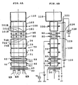
- the electron gun structure 16, as shown in Figure 4A, includes three cathodes KR, KG and KB linearly arranged and housing heaters (not shown ), respectively.
- the electron gun structure 19 also includes a first electrode 30, a second electrode 40, a third electrode 50, a fourth electrode 60, a fifth electrode 70, two intermediate electrodes 80 and 90, a sixth electrode 100 and a convergence cup 110. These electrodes are supported by a pair of insulating rod (not shown ).
- a resistor 120 is provided near the electron gun structure 16 to supply the predetermined constant voltages to the intermediate electrodes 80 and 90.
- One end terminal 121 of the resistor 120 is connected to the sixth electrode 100 and another end terminal 122 is connected to ground.
- An intermediate terminals 123 and 124 of the resistor 120 are connected to the intermediate electrodes 80 and 90, respectively. Also, the terminal 121 of the resistor 120 is connected to working voltage supply system 130.
- the resistor shown in U. S. Patent No. 4,672,269 issued on January 9, 1987 may be used as the resistor 120 of the invention.
- the first electrode 30 is made of a thin plate electrode with three small holes linealy arranged in the horizontal direction for the path of the electron beam.
- the second electrode 40 is also made of a thin plate electrode with three small holes linearly arranged.
- the third electrode 50 consists of first and second cup-shaped electrodes 51 and 52 which are fixed together at their open ends.
- the first cup-shaped electrode 51 has three holes with slightly larger diameter than that of holes of the second electrode 40 on the side of the second electrode 40.
- the second cup-shaped electrode 52 has three holes with larger diameter than that of the holes of the first cup-shaped electrode 51 on the side of the fourth electrode 60.
- the fourth electrode 60 also consists of first and second cup-shaped electrodes 61 and 62 which are fixed together at their open ends.
- the first and second cup-shaped electrodes 61 and 62 have three holes with large diameter, respectively.
- the fifth electrode 70 consists of four cup-shaped electrodes 71, 72, 73 and 74, each of which has three large-diameter holes.
- the intermediate electrodes 80 and 90 are made of thick plate electrodes with three large-diameter holes.
- the sixth electrode 100 is composed of two cup-shaped electrodes 101 and 102, each of which has three large-diameter holes.
- the convergence cup 110 is secured to the bottom of the cup-shaped electrode 102. All of the electrodes from the first electrode 30 to the convergence cup 110 have circular holes.
- the electrodes are applied the following voltages, respectively.
- the cathodes KR, KG and KB are supplied, for example, direct current voltages of 150V and modulated image signals corresponding to the picture image, respectively.
- the first electrode 30 is connected to ground potential and direct current voltages of about 600V is supplied on the second electrode 40.
- the cathodes KR, KG and KB, the first electrode 30 and the second electrode 40 construct a triode.
- the third and fifth electrodes 50 and 70 are connected in the inside of the envelope and are applied about 7kV to 8kV as focusing voltage. These electrodes 50 and 70 are also superimposed dynamic focusing voltage V D which varies in accordance with the deflection angle.
- the fourth electrode 60 is connected to the second electrode 40 in the inside of the envelope. Also, an accelerating voltage of about 25kV to 30kV is impressed on the sixth electrode 100.
- the second and third electrode 40 and 50 form a pre-focus lens which preliminarily focuses the electron beams passing through the triode.
- the third, fourth and fifth electrode 50, 60 and 70 form an auxiliary focusing lens and the electron beams are further focused at the auxiliary focusing lens.
- the voltages of 40% and 65% of the accelerating voltage is applied to the intermediate electrodes 80 and 90 thruogh the resistor 120.
- the fifth electrode 70, intermediate electrodes 80 and 90 and the sixth electrode1 100 form the main focusing lens which focuses respective electron beam and converges three electron beams on the phosphor screen.
- the main focusing lens can be made a lens with a long focal length called an expanded electric field lens.
- FIG. 5A showing a horizontal cross-section of the electric field, converging electric field between the cup-shaped electrode 74 and one of the intermediate electrode 80, which penetrates into the last cup-shaped electrode 74 of the fifth electrode 70, consists of the equipotential lines which are common to the center hole 74G and both side holes 74R and 74B.
- the equipotential lines in the horizontal cross-section are common to these holes 74G, 74R and 74B, the curvature of the electric fields are small.
- the main focusing lens of the electron gun 16 consists of the converging electric field near the fifth electrode 70 and the diverging electric field near the sixth electrode 100 which are independantly separated each other by the intermediate electrodes 80 and 90. Further, since the curvature of the converging and diverging electric field in the vertical direction are relatively larger than in the horizontal direction, the main focusing lens has a converging action relatively stronger in the vertical direction and diverging action relatively stronger in the vertical direction. The action of the main focusing lens will be explained. When the electron beams are projected at the center of the screen, respective electron beams are focused into an almost circular shape by applying a predetermined focusing voltage to the fifth electrode 70 so that the asymmetric converging electric field and the asymmetric diverging electric field are balanced.
- the focusing voltage is increased over the predetermined value in accordance with the deflection angle.
- the converging electric field becomes weaker.
- the diverging electric field between the intermediate electrode 90 and sixth electrode 100 does not vary. So, the diverging electric field becomes relatively stronger in the main focusing lens compared with the converging electric field. Accordingly, for the electron beam, an under-focused state occurs in the vertical direction, and thus, the over-focused state caused by the deflection magnetic field can be cancelled out.
- the main focusing lens of the horizontal direction can be represented by the combination of a relatively weak converging lens ( convex lens ) 200 and diverging lens ( concave lens ) 300 when no deflection is imparted.
- the main focusing lens of the vertical direction can be also represented by the combination of a relatively strong converging lens 210 and diverging lens 310. So, the electron beam is focused on the screen in both of the horizontal and vertical direction, and an circular beam spot is obtained.
- Figures 8A and 8B show horizontal and vertical cross-section of the equipotential distribution, respectively.
- strong converging electric field is formed in the vertical direction of the main focusing lens near the focusing electrode 70 and a strong diverging electric field is also formed in the vertical direction as well as the electron gun of this embodiment.
- the diverging electric field becomes weaker when the focusing voltage is increased in order that the converging electric field is to be weaker. Therefore, the optimum beam focusing state on the screen is not obtained at the periphery of the screen.
- Figures 9 and 10 show the optical models when the electron beam is projected on the center and periphery of the screen, respectively.
- the converging lens and the diverging lens in the vertical direction both become weak due to the increased focusing voltage when the electron beam is projected on the periphery of the screen. So, it is impossible to achieve the under-focused state of the electron beam in the vertical direction alone. Consequently, the beam distortion due to the deflection magnetic field is not compensated.
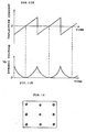
- the fifth electrode 70 of this embodiment is applied the dynamic voltage V D show in Figure 11B which is superimposed on the focusing voltage in synchronisation with the deflection of the electron beam.
- the deflection current shown in Figure 11A is zero, namely, when the electron beam is projected at the center of the screen, the dynamic voltage is also zero.
- the dynamic voltage As the electron beam is deflected to the screen periphery, the dynamic voltage also rises in a parabolic curve. Since the focusing voltage rises in synchronisation with the deflection to the screen periphery, as described above, it is possible to achieve the under-focused state of the electron beams in the vertical direction alone.
- the dynamic voltage can be superimposed on the focusing voltage, the conventional socket unit with one terminal for supplying the focusing voltage can be used.
- the electron beam spot configuration of the embodiment is almost circular in the center of the screen, and, at the screen periphery, the halo in the vertical direction can be almost eliminated, as shown in Figure 12. Therefore, high resolution can be realized over the entire screen.
- the fifth electrode and the sixth electrode have the circular holes on the intermediate electrode sides
- elliptically-shaped holes 74R′, 74G′ and 74B′ having the long axis in the horizontal direction can be used, as shown in Figure 13. Due to the elongated hole, the converging electric field is further strengthened in the vertical direction and the diverging electric field is also further strengthened in the vertical direction.
- the ratio of the long axis to the short axis of the elliptical holes may be made the same in both the fifth and the sixth electrodes, or they may be made to differ.
- the ratio of the center holes 74G′(101G′) to the holes on both sides holes 74R′(101R′) and 74B′(101B′) may also be differ.
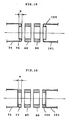
- a pair of plate-shaped components 300 may be arranged with the condition of facing each other in the vertical direction in the inside of the last cup-shaped electrode 74 of the fifth electrode 70 and the cup-shaped electrode 101 of the sixth electrode 100.
- the converging electric field is further strengthened in the vertical direction and the diverging electric field is also further strengthened in the vertical direction.
- the length l of the plate-shaped components 300 in the axial direction of the tube is made longer, the strength of the electric fields in the vertical direction can be increased.
- the length l in the axial direction of the tube of the component 300 which are arranged in the inside of the fifth and sixth electrodes may be the same or different. Also, the elliptical hole shown in Figure 13 and the component shown in Figure 14 may be combined. In this complex electrode, the strengths of the asymmetric converging and diverging electric field will become even stronger than those in the embodiments shown in Figures 13 and 14. It is also possible to eleminate superimposing the dynamic focusing voltage by employing these complex electrodes.
- cylindrical walls 76 and 103 which inwardly extend to the hole may be provided in one or both of the fifth and sixth electrodes. If the length k of cylindrical walls 76 and 103 is made longer, the asymmetry is weakened in the case of circular hole, but the asymmetry is strengthened in the case of elliptical hole. Also, as shown in Figure 16, thick plate-shaped component 77 and 104 may be added to one or both of the fifth and sixth electrodes. If thickness m of these thick plate-shaped component is increased, the asymmetry is weakened in the case of circular holes, but the asymmetry is strengthened in the case of elliptical hole.
- this invention can be applied to other combined electron guns and can also be applied to the bi-potential type and unipotential type electron gun. Also, although the electron gun having two intermediate electrodes, this invention can be applied to the electron gun having one intermediate electrode and more than three intermediate electrodes.
- this invention can also be applied to other multi-beam system and single beam system. Furthermore, this invention can be also applied to the delta type electron gun.
Landscapes
- Video Image Reproduction Devices For Color Tv Systems (AREA)
- Cathode-Ray Tubes And Fluorescent Screens For Display (AREA)
Applications Claiming Priority (2)
| Application Number | Priority Date | Filing Date | Title |
|---|---|---|---|
| JP62194448A JP2542627B2 (ja) | 1987-08-05 | 1987-08-05 | カラ−受像管装置 |
| JP194448/87 | 1987-08-05 |
Publications (3)
| Publication Number | Publication Date |
|---|---|
| EP0302657A2 true EP0302657A2 (fr) | 1989-02-08 |
| EP0302657A3 EP0302657A3 (en) | 1990-05-30 |
| EP0302657B1 EP0302657B1 (fr) | 1994-03-30 |
Family
ID=16324739
Family Applications (1)
| Application Number | Title | Priority Date | Filing Date |
|---|---|---|---|
| EP88306913A Expired - Lifetime EP0302657B1 (fr) | 1987-08-05 | 1988-07-27 | Structure de canon à électrons pour appareil à tube-image couleur |
Country Status (6)
| Country | Link |
|---|---|
| US (1) | US4897575A (fr) |
| EP (1) | EP0302657B1 (fr) |
| JP (1) | JP2542627B2 (fr) |
| KR (1) | KR910007830B1 (fr) |
| CN (1) | CN1016914B (fr) |
| DE (1) | DE3888748T2 (fr) |
Cited By (9)
| Publication number | Priority date | Publication date | Assignee | Title |
|---|---|---|---|---|
| EP0334197A3 (fr) * | 1988-03-17 | 1990-05-30 | Kabushiki Kaisha Toshiba | Dispositif de canon à électrons pour tube à rayons cathodiques |
| EP0441486A3 (en) * | 1990-02-08 | 1992-01-29 | Hitachi, Ltd. | Electron gun and cathode-ray tube |
| EP0596443A1 (fr) * | 1992-11-02 | 1994-05-11 | Kabushiki Kaisha Toshiba | Tube à rayons cathodique couleur |
| EP0641010A3 (fr) * | 1993-08-25 | 1996-02-07 | Chunghwa Picture Tubes Ltd | Correction dynamique de défocalisation désaxée pour tube à rayons cathodiques à lentille de déflexion. |
| WO1998031040A1 (fr) * | 1997-01-13 | 1998-07-16 | Kabushiki Kaisha Toshiba | Tube-image couleur |
| US5877587A (en) * | 1994-08-26 | 1999-03-02 | Thomson Tubes And Displays, S.A. | Inline electron gun having improved expanded focus lens electrodes |
| US6271625B1 (en) | 1994-08-25 | 2001-08-07 | U.S. Philips Corporation | Picture display device provided with an electron gun, and electron gun for use in such a device |
| US6504296B2 (en) | 1998-12-28 | 2003-01-07 | Siemens Aktiengesellschaft | Tube neck for cathode ray tube |
| EP0996140A4 (fr) * | 1998-03-13 | 2006-12-06 | Toshiba Kk | Tube cathodique |
Families Citing this family (17)
| Publication number | Priority date | Publication date | Assignee | Title |
|---|---|---|---|---|
| US5010271A (en) * | 1989-10-24 | 1991-04-23 | Rca Licensing Corporation | Color picture tube having an electron gun with reduced convergence drift |
| GB9104649D0 (en) * | 1991-03-05 | 1991-04-17 | Secr Defence | Focusing means for cathode ray tubes |
| JP3599765B2 (ja) * | 1993-04-20 | 2004-12-08 | 株式会社東芝 | 陰極線管装置 |
| JPH0729512A (ja) * | 1993-05-14 | 1995-01-31 | Toshiba Corp | カラー受像管 |
| CH686327A5 (de) * | 1993-08-17 | 1996-02-29 | Abb Management Ag | Gasgekuehlte elektrische Maschine. |
| JP3576217B2 (ja) * | 1993-09-30 | 2004-10-13 | 株式会社東芝 | 受像管装置 |
| TW272299B (fr) * | 1994-08-01 | 1996-03-11 | Toshiba Co Ltd | |
| JP2000048738A (ja) * | 1998-07-27 | 2000-02-18 | Toshiba Corp | カラー陰極線管 |
| JP2000156178A (ja) | 1998-11-20 | 2000-06-06 | Toshiba Corp | 陰極線管 |
| TW446984B (en) | 1999-01-26 | 2001-07-21 | Toshiba Corp | Color cathode ray tube device |
| KR100291926B1 (ko) * | 1999-03-29 | 2001-06-01 | 김순택 | 칼라 음극선관의 인라인형 전자총 |
| JP2000357469A (ja) | 1999-06-16 | 2000-12-26 | Toshiba Electronic Engineering Corp | カラーブラウン管装置 |
| JP2001057163A (ja) | 1999-08-19 | 2001-02-27 | Toshiba Electronic Engineering Corp | カラーブラウン管装置 |
| JP2001216916A (ja) | 2000-01-31 | 2001-08-10 | Toshiba Corp | 陰極線管装置 |
| JP2001283751A (ja) | 2000-03-29 | 2001-10-12 | Toshiba Corp | 陰極線管装置 |
| JP2002042681A (ja) | 2000-07-26 | 2002-02-08 | Toshiba Corp | 陰極線管装置 |
| KR100777710B1 (ko) * | 2001-07-05 | 2007-11-21 | 삼성에스디아이 주식회사 | 칼라 음극선관용 전자총 |
Family Cites Families (7)
| Publication number | Priority date | Publication date | Assignee | Title |
|---|---|---|---|---|
| US4443736A (en) * | 1981-09-23 | 1984-04-17 | Rca Corporation | Electron gun for dynamic beam shape modulation |
| EP0152933B1 (fr) * | 1984-02-20 | 1988-03-02 | Kabushiki Kaisha Toshiba | Canon à électrons |
| US4701677A (en) * | 1984-07-30 | 1987-10-20 | Matsushita Electronics Corporation | Color cathode ray tube apparatus |
| CA1265838A (fr) * | 1985-06-12 | 1990-02-13 | Albertus A.S. Sluyterman | Tube image couleur a correction de l'aberration en coma |
| NL8600117A (nl) * | 1986-01-21 | 1987-08-17 | Philips Nv | Kleurenbeeldbuis met verminderde deflectie defocussering. |
| JPH07111879B2 (ja) * | 1986-02-14 | 1995-11-29 | 株式会社東芝 | カラ−受像管装置 |
| US4887009A (en) * | 1986-02-12 | 1989-12-12 | Rca Licensing Corporation | Color display system |
-
1987
- 1987-08-05 JP JP62194448A patent/JP2542627B2/ja not_active Expired - Lifetime
-
1988
- 1988-07-25 US US07/223,332 patent/US4897575A/en not_active Expired - Lifetime
- 1988-07-27 DE DE3888748T patent/DE3888748T2/de not_active Expired - Lifetime
- 1988-07-27 EP EP88306913A patent/EP0302657B1/fr not_active Expired - Lifetime
- 1988-08-05 KR KR1019880010003A patent/KR910007830B1/ko not_active Expired
- 1988-08-05 CN CN88104880A patent/CN1016914B/zh not_active Expired
Cited By (11)
| Publication number | Priority date | Publication date | Assignee | Title |
|---|---|---|---|---|
| EP0334197A3 (fr) * | 1988-03-17 | 1990-05-30 | Kabushiki Kaisha Toshiba | Dispositif de canon à électrons pour tube à rayons cathodiques |
| EP0441486A3 (en) * | 1990-02-08 | 1992-01-29 | Hitachi, Ltd. | Electron gun and cathode-ray tube |
| EP0596443A1 (fr) * | 1992-11-02 | 1994-05-11 | Kabushiki Kaisha Toshiba | Tube à rayons cathodique couleur |
| US5486735A (en) * | 1992-11-02 | 1996-01-23 | Kabushiki Kaisha Toshiba | Electron gun with improved withstand voltage for color-picture tube |
| EP0641010A3 (fr) * | 1993-08-25 | 1996-02-07 | Chunghwa Picture Tubes Ltd | Correction dynamique de défocalisation désaxée pour tube à rayons cathodiques à lentille de déflexion. |
| US6271625B1 (en) | 1994-08-25 | 2001-08-07 | U.S. Philips Corporation | Picture display device provided with an electron gun, and electron gun for use in such a device |
| US5877587A (en) * | 1994-08-26 | 1999-03-02 | Thomson Tubes And Displays, S.A. | Inline electron gun having improved expanded focus lens electrodes |
| WO1998031040A1 (fr) * | 1997-01-13 | 1998-07-16 | Kabushiki Kaisha Toshiba | Tube-image couleur |
| US6313575B1 (en) | 1997-01-13 | 2001-11-06 | Kabushiki Kaisha Toshiba | Color picture tube |
| EP0996140A4 (fr) * | 1998-03-13 | 2006-12-06 | Toshiba Kk | Tube cathodique |
| US6504296B2 (en) | 1998-12-28 | 2003-01-07 | Siemens Aktiengesellschaft | Tube neck for cathode ray tube |
Also Published As
| Publication number | Publication date |
|---|---|
| US4897575A (en) | 1990-01-30 |
| CN1032266A (zh) | 1989-04-05 |
| KR910007830B1 (ko) | 1991-10-02 |
| CN1016914B (zh) | 1992-06-03 |
| EP0302657A3 (en) | 1990-05-30 |
| EP0302657B1 (fr) | 1994-03-30 |
| JPS6438947A (en) | 1989-02-09 |
| KR890004380A (ko) | 1989-04-21 |
| JP2542627B2 (ja) | 1996-10-09 |
| DE3888748D1 (de) | 1994-05-05 |
| DE3888748T2 (de) | 1994-08-04 |
Similar Documents
| Publication | Publication Date | Title |
|---|---|---|
| EP0302657B1 (fr) | Structure de canon à électrons pour appareil à tube-image couleur | |
| US4814670A (en) | Cathode ray tube apparatus having focusing grids with horizontally and vertically oblong through holes | |
| EP0986088B1 (fr) | Tube à rayons cathodique ayant un faible potentiel de focalisation dynamique | |
| JP2605202B2 (ja) | カラー陰極線管用電子銃 | |
| US4935663A (en) | Electron gun assembly for color cathode ray tube apparatus | |
| US5066887A (en) | Color picture tube having an inline electron gun with an astigmatic prefocusing lens | |
| US5162695A (en) | Electron gun assembly for a color cathode ray tube | |
| KR100345613B1 (ko) | 칼라음극선관 | |
| US6927531B2 (en) | Electron gun and color picture tube apparatus that attain a high degree of resolution over the entire screen | |
| JPH052999A (ja) | カラー受像管 | |
| US5633567A (en) | Display device and cathode ray tube | |
| US6646381B2 (en) | Cathode-ray tube apparatus | |
| KR970006037B1 (ko) | 개선된 전자총을 갖는 음극선관 | |
| JPH0636705A (ja) | カラー受像管 | |
| GB2281657A (en) | Electron gun with astigmatism correction | |
| US6628061B2 (en) | Electron gun for cathode ray tube | |
| KR940003244Y1 (ko) | 음극선관용 전자총 | |
| KR100252959B1 (ko) | 칼라 음극선관용 전자총 | |
| KR100236105B1 (ko) | 칼라음극선관용 전자총 | |
| KR100267978B1 (ko) | 칼라 음극선관용 전자총 | |
| KR940008761B1 (ko) | 칼라 음극선관용 전자총 | |
| US6586869B1 (en) | Electrodes of electron gun | |
| JPH09134680A (ja) | カラー受像管装置 | |
| JP2000285823A (ja) | カラーブラウン管装置 | |
| KR20000038581A (ko) | 칼라 음극선관용 전자총 |
Legal Events
| Date | Code | Title | Description |
|---|---|---|---|
| PUAI | Public reference made under article 153(3) epc to a published international application that has entered the european phase |
Free format text: ORIGINAL CODE: 0009012 |
|
| 17P | Request for examination filed |
Effective date: 19880808 |
|
| AK | Designated contracting states |
Kind code of ref document: A2 Designated state(s): DE FR GB |
|
| PUAL | Search report despatched |
Free format text: ORIGINAL CODE: 0009013 |
|
| AK | Designated contracting states |
Kind code of ref document: A3 Designated state(s): DE FR GB |
|
| 17Q | First examination report despatched |
Effective date: 19921201 |
|
| GRAA | (expected) grant |
Free format text: ORIGINAL CODE: 0009210 |
|
| AK | Designated contracting states |
Kind code of ref document: B1 Designated state(s): DE FR GB |
|
| ET | Fr: translation filed | ||
| REF | Corresponds to: |
Ref document number: 3888748 Country of ref document: DE Date of ref document: 19940505 |
|
| PLBE | No opposition filed within time limit |
Free format text: ORIGINAL CODE: 0009261 |
|
| STAA | Information on the status of an ep patent application or granted ep patent |
Free format text: STATUS: NO OPPOSITION FILED WITHIN TIME LIMIT |
|
| 26N | No opposition filed | ||
| REG | Reference to a national code |
Ref country code: GB Ref legal event code: 746 Effective date: 19981015 |
|
| REG | Reference to a national code |
Ref country code: FR Ref legal event code: D6 |
|
| REG | Reference to a national code |
Ref country code: GB Ref legal event code: IF02 |
|
| PGFP | Annual fee paid to national office [announced via postgrant information from national office to epo] |
Ref country code: DE Payment date: 20070719 Year of fee payment: 20 |
|
| PGFP | Annual fee paid to national office [announced via postgrant information from national office to epo] |
Ref country code: GB Payment date: 20070725 Year of fee payment: 20 |
|
| PGFP | Annual fee paid to national office [announced via postgrant information from national office to epo] |
Ref country code: FR Payment date: 20070710 Year of fee payment: 20 |
|
| REG | Reference to a national code |
Ref country code: GB Ref legal event code: PE20 Expiry date: 20080726 |
|
| PG25 | Lapsed in a contracting state [announced via postgrant information from national office to epo] |
Ref country code: GB Free format text: LAPSE BECAUSE OF EXPIRATION OF PROTECTION Effective date: 20080726 |