EP0302977A1 - Vorrichtung zum Nachweis oder zur Beobachtung von Schwebestoffen in Fluiden - Google Patents
Vorrichtung zum Nachweis oder zur Beobachtung von Schwebestoffen in Fluiden Download PDFInfo
- Publication number
- EP0302977A1 EP0302977A1 EP87307218A EP87307218A EP0302977A1 EP 0302977 A1 EP0302977 A1 EP 0302977A1 EP 87307218 A EP87307218 A EP 87307218A EP 87307218 A EP87307218 A EP 87307218A EP 0302977 A1 EP0302977 A1 EP 0302977A1
- Authority
- EP
- European Patent Office
- Prior art keywords
- light
- viewing
- floating
- viewing chamber
- fluid
- Prior art date
- Legal status (The legal status is an assumption and is not a legal conclusion. Google has not performed a legal analysis and makes no representation as to the accuracy of the status listed.)
- Withdrawn
Links
- 239000000463 material Substances 0.000 title claims abstract description 18
- 239000012530 fluid Substances 0.000 title claims description 17
- 230000003287 optical effect Effects 0.000 claims abstract description 11
- 239000007788 liquid Substances 0.000 claims abstract description 8
- 238000007789 sealing Methods 0.000 claims abstract description 3
- XLYOFNOQVPJJNP-UHFFFAOYSA-N water Substances O XLYOFNOQVPJJNP-UHFFFAOYSA-N 0.000 abstract description 12
- 239000000428 dust Substances 0.000 abstract description 10
- 239000002245 particle Substances 0.000 abstract description 6
- 230000007246 mechanism Effects 0.000 description 8
- 238000011109 contamination Methods 0.000 description 3
- 238000005259 measurement Methods 0.000 description 2
- 239000000126 substance Substances 0.000 description 2
- 208000032368 Device malfunction Diseases 0.000 description 1
- 238000004140 cleaning Methods 0.000 description 1
- 230000005183 environmental health Effects 0.000 description 1
- 239000004744 fabric Substances 0.000 description 1
- 239000011521 glass Substances 0.000 description 1
- 230000036541 health Effects 0.000 description 1
- 235000021056 liquid food Nutrition 0.000 description 1
- 229920003002 synthetic resin Polymers 0.000 description 1
- 239000000057 synthetic resin Substances 0.000 description 1
Images

Classifications
-
- G—PHYSICS
- G01—MEASURING; TESTING
- G01N—INVESTIGATING OR ANALYSING MATERIALS BY DETERMINING THEIR CHEMICAL OR PHYSICAL PROPERTIES
- G01N21/00—Investigating or analysing materials by the use of optical means, i.e. using sub-millimetre waves, infrared, visible or ultraviolet light
- G01N21/17—Systems in which incident light is modified in accordance with the properties of the material investigated
- G01N21/47—Scattering, i.e. diffuse reflection
- G01N21/49—Scattering, i.e. diffuse reflection within a body or fluid
- G01N21/51—Scattering, i.e. diffuse reflection within a body or fluid inside a container, e.g. in an ampoule
-
- G—PHYSICS
- G01—MEASURING; TESTING
- G01N—INVESTIGATING OR ANALYSING MATERIALS BY DETERMINING THEIR CHEMICAL OR PHYSICAL PROPERTIES
- G01N21/00—Investigating or analysing materials by the use of optical means, i.e. using sub-millimetre waves, infrared, visible or ultraviolet light
- G01N21/17—Systems in which incident light is modified in accordance with the properties of the material investigated
- G01N21/25—Colour; Spectral properties, i.e. comparison of effect of material on the light at two or more different wavelengths or wavelength bands
- G01N21/29—Colour; Spectral properties, i.e. comparison of effect of material on the light at two or more different wavelengths or wavelength bands using visual detection
Definitions
- This invention relates to a device for detecting or viewing floating materials in fluids. More particularly, it relates to a floating material viewing device for taking in a gas such as air or liquid such as water and liquid food (these gas and liquid will be hereinafter referred to as fluid) and enabling matters floating in the fluid to be viewed with eyes.
- a gas such as air or liquid
- fluid these gas and liquid will be hereinafter referred to as fluid
- a floating material viewing device comprises a means for sealing a fluid shaded from light in a viewing chamber, a light source for providing a beam of light in the fluid in the viewing chamber, and an optical means for magnifying floating matters appearing in the beam of light to be viewed by eye.
- An object of the present invention is therefore to provide a floating material viewing device capable of taking in a fluid and viewing materials floating in the fluid by eye.
- Fig. 1 shows an example of the floating materials viewing device according to the present invention, which is intended to view dust floating in the air which is a typical gas.
- the viewing device comprises a light source 10, which is turned on and off by a switch 12, using a battery 11 as a power source.
- Light emitted from the light source 10 is focused by a mirror 13 and a lens 14 and introduced into a viewing chamber 20, after passing through a slit or pinhole 15, to provide a belt - or line-like light beam 16 in the viewing chamber 20.
- a light shield 21 which is an electrically - or manually-operated shutter or cap.
- the mechanism of the lens shutter in the camera, light-shading plate or screen can be used as the light-shield.
- the viewing chamger 20 is shielded from light by means of the hand, for example.
- the belt - or line-like light beam in the viewing chamber 20 is formed as described above, but the present invention is not limited to the above-described embodiment.
- a plate having the slit and the pinhole 15, for example, may be prepared to use the slit and the pinhole alternately.
- the focusing mechanism in the camera may be used.
- the lens 14 may not be used.
- the belt - or line-like light beam in the viewing chamber 20 may be formed by directing the slit or pinhole 15 towards a bright light such as sunlight and illuminating light, without using the light source 10.
- the light beam extending from the light source 10 may be changed using a prism, half-mirror or the like.
- a single or plural colour filters 17 may be arranged in the path of the light beam extending from the light source 10 to colour the light beam 16.
- the colour of the light beam 16 may be optionally changed.
- a pair of light-shield mechanisms 21 are arranged one to each side of the light beam 16 as shown in Fig. 2.
- air to be viewed can be fully taken in the viewing chamber 20, keeping the light-shield mechanisms 21 opened, and the air which is thus uniform can be caught in the viewing chamber 20, closing the light-shield mechanisms 21.
- the light-shield mechanisms 21 may be formed by a movable member 22 and the viewing chamber 20 may be opened and closed by sliding the movable member 22 in the directions shown by arrows.
- the movable member 22 may be pivoted on sides of the frame body and swung round a pivot shaft to open and close the viewing chamber 20.
- a bag-like cloth may, for example, be used instead of the movable member 22.
- Fig. 1 there are transparent plates 30, 31 made of glass, synthetic resin or the like which serve to prevent floating dust taken into the viewing chamber 20 or dust floating in rhe air outside from entering an optical system which will be later described.
- the transparent plate 30 is attached in a water-tight manner to the frame body.
- a single magnifying lens or a group of the magnifying lenses 40 which serve as an optical means for magnifying dust particles floating in the light beam 16 to be viewed by eye. It is preferable that a camera is attached to a mount or directly to the optical system to take photographs. An "instant" camera made by Polaroid Corporation may be preferably used.
- Air to be viewed is taken into the viewing chamber 20, by opening the light-shield mechanisms 21, and a certain amount of the air is caught in the viewing chamber 20, closing the light-shielding mechanisms 21.
- the light source 10 is turned on, or the slit or pinhole 15 is directed to the light source, the belt - or line-like light beam 16 is projected in the viewing chamber 20. Dust particles floating in the air in the viewing chamber 20 thus appear in the light beam 16 and they are magnified by the optical system, thereby enabling them to be easily viewed with the eyes.
- magnification is changed by the optical system or the colour of the light beam 16 is changed by the colour filters 17, their kind, size and state can be checked.
- the instant camera is set, they can be recorded as images.
- a well-known sensor is arranged inside or outside the viewing chamber 20 to detect the density or kind of chemical components in the air and display it by digital - or analog-display, the chemical components being except those which compose the air, viewing with eyes becomes more interesting.
- a transparent plate is attached to the slit to make the viewing chamber 20 water-tight and water is admitted to the thus-formed viewing chamber 20.
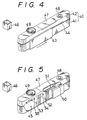
- a frame 40 of a light-shield structure comprising an upper half 41 and a lower half 42.
- This frame structure includes those which are made by a single or three or more members.
- a slide member 43 is movable along a guide groove 44 in a direction shown by an arrow and also in a direction reverse to the arrow to open and close a viewing chamber 45 shown in Fig. 5.
- the viewing chamber 45 is opened to introduce a fluid therein to view materials floating in the fluid.
- the viewing chamber 45 is closed so as to be water-tight.
- the gas can be introduced into the viewing chamber 45 only by moving the slide member 43 in two directions, but when the fluid is a liquid, a small transparent container 46 is used.
- a battery housing section has a cap 47, a switch 48, for turning the light source on and off and an optical system 49.
- a lamp 50 serves as the light source and is turned on and off by the switch 48, using a battery 51 as the power source.
- Light emitted from the lamp 50 passes through small holes 54 and 55 in shield plates 52 and 53 to form a light beam 56, as shown by a broken line, in the viewing chamber 45.
- This light beam 56 crosses the optical axis of the lens system 49. In other words, the focus of the lens exists in the light beam 56 extending from the light source.
Landscapes
- Physics & Mathematics (AREA)
- Health & Medical Sciences (AREA)
- Life Sciences & Earth Sciences (AREA)
- Chemical & Material Sciences (AREA)
- Analytical Chemistry (AREA)
- Biochemistry (AREA)
- General Health & Medical Sciences (AREA)
- General Physics & Mathematics (AREA)
- Immunology (AREA)
- Pathology (AREA)
- Investigating Or Analysing Materials By Optical Means (AREA)
Priority Applications (1)
| Application Number | Priority Date | Filing Date | Title |
|---|---|---|---|
| EP87307218A EP0302977A1 (de) | 1987-08-14 | 1987-08-14 | Vorrichtung zum Nachweis oder zur Beobachtung von Schwebestoffen in Fluiden |
Applications Claiming Priority (1)
| Application Number | Priority Date | Filing Date | Title |
|---|---|---|---|
| EP87307218A EP0302977A1 (de) | 1987-08-14 | 1987-08-14 | Vorrichtung zum Nachweis oder zur Beobachtung von Schwebestoffen in Fluiden |
Publications (1)
| Publication Number | Publication Date |
|---|---|
| EP0302977A1 true EP0302977A1 (de) | 1989-02-15 |
Family
ID=8197998
Family Applications (1)
| Application Number | Title | Priority Date | Filing Date |
|---|---|---|---|
| EP87307218A Withdrawn EP0302977A1 (de) | 1987-08-14 | 1987-08-14 | Vorrichtung zum Nachweis oder zur Beobachtung von Schwebestoffen in Fluiden |
Country Status (1)
| Country | Link |
|---|---|
| EP (1) | EP0302977A1 (de) |
Citations (4)
| Publication number | Priority date | Publication date | Assignee | Title |
|---|---|---|---|---|
| US1516608A (en) * | 1921-06-28 | 1924-11-25 | Kidde & Co Walter | Detection of suspended matter in gases |
| US1807659A (en) * | 1928-02-25 | 1931-06-02 | of new yobk | |
| GB1024734A (en) * | 1963-05-06 | 1966-04-06 | British Petroleum Co | Improvements relating to the detection of solid particles suspended in liquid |
| DE1969803U (de) * | 1967-04-26 | 1967-10-05 | Pyrotector G M B H | Lichtdichtes gehaeuse fuer lichtoptische nachweisvorrichtungen. |
-
1987
- 1987-08-14 EP EP87307218A patent/EP0302977A1/de not_active Withdrawn
Patent Citations (4)
| Publication number | Priority date | Publication date | Assignee | Title |
|---|---|---|---|---|
| US1516608A (en) * | 1921-06-28 | 1924-11-25 | Kidde & Co Walter | Detection of suspended matter in gases |
| US1807659A (en) * | 1928-02-25 | 1931-06-02 | of new yobk | |
| GB1024734A (en) * | 1963-05-06 | 1966-04-06 | British Petroleum Co | Improvements relating to the detection of solid particles suspended in liquid |
| DE1969803U (de) * | 1967-04-26 | 1967-10-05 | Pyrotector G M B H | Lichtdichtes gehaeuse fuer lichtoptische nachweisvorrichtungen. |
Non-Patent Citations (1)
| Title |
|---|
| H.R. KRUYT "Colloid Science", vol. 1, 1952, pages 34-39, "Irreversible systems", Eysevier Publishing Co., Amsterdam, NL; * |
Similar Documents
| Publication | Publication Date | Title |
|---|---|---|
| US4198161A (en) | Low turbidity nephelometer | |
| US3900252A (en) | Method and apparatus for analyzing hair structure | |
| US5701534A (en) | Seal apparatus of finder | |
| US3417685A (en) | Stereoscopic photographing device and photographing direction indicator for such device | |
| US3997258A (en) | Film reader | |
| RU99115741A (ru) | Устройство для определения местоположения источников излучения | |
| US4206966A (en) | Projection microscope with film holder | |
| EP0302977A1 (de) | Vorrichtung zum Nachweis oder zur Beobachtung von Schwebestoffen in Fluiden | |
| JPH04218878A (ja) | イメージセンサー用防塵装置 | |
| US4498749A (en) | Folded optical large format photomicrographic camera system | |
| KR900005241B1 (ko) | 부유물 관찰장치 | |
| JPH08338947A (ja) | 蛍光顕微鏡の蛍光装置 | |
| US4037926A (en) | Photographic film reading instrument | |
| US4589742A (en) | Microscope for observing environmentally sensitive objects | |
| JPS62188939A (ja) | 浮遊物観察装置 | |
| US4191457A (en) | Bi-directional optical apparatus for altering an optically projected member | |
| US4761065A (en) | Inspection device with adjustable viewing screen | |
| US3619623A (en) | Examination of fluid suspensions of particulated matter | |
| JPH0633408Y2 (ja) | 粉塵目視装置 | |
| JP5007470B2 (ja) | 透明体検査装置 | |
| US3079503A (en) | Negative to positive microscope | |
| RU2375699C2 (ru) | Улучшенное устройство обнаружения | |
| US3366003A (en) | Photographic apparatus | |
| JP3344756B2 (ja) | 測光絞り装置 | |
| US3611897A (en) | Photographic instrument |
Legal Events
| Date | Code | Title | Description |
|---|---|---|---|
| PUAI | Public reference made under article 153(3) epc to a published international application that has entered the european phase |
Free format text: ORIGINAL CODE: 0009012 |
|
| AK | Designated contracting states |
Kind code of ref document: A1 Designated state(s): DE FR GB |
|
| STAA | Information on the status of an ep patent application or granted ep patent |
Free format text: STATUS: THE APPLICATION IS DEEMED TO BE WITHDRAWN |
|
| 18D | Application deemed to be withdrawn |
Effective date: 19890816 |
|
| RIN1 | Information on inventor provided before grant (corrected) |
Inventor name: KOHADA, TAKEO |