EP0303053B2 - Dispositif de transfert de feuilles - Google Patents
Dispositif de transfert de feuilles Download PDFInfo
- Publication number
- EP0303053B2 EP0303053B2 EP88110921A EP88110921A EP0303053B2 EP 0303053 B2 EP0303053 B2 EP 0303053B2 EP 88110921 A EP88110921 A EP 88110921A EP 88110921 A EP88110921 A EP 88110921A EP 0303053 B2 EP0303053 B2 EP 0303053B2
- Authority
- EP
- European Patent Office
- Prior art keywords
- sheet
- feed
- feed table
- impression cylinder
- printing
- Prior art date
- Legal status (The legal status is an assumption and is not a legal conclusion. Google has not performed a legal analysis and makes no representation as to the accuracy of the status listed.)
- Expired - Lifetime
Links
- 238000007639 printing Methods 0.000 claims description 46
- 239000003550 marker Substances 0.000 claims description 9
- 230000001133 acceleration Effects 0.000 claims description 7
- 230000001154 acute effect Effects 0.000 claims description 4
- 230000002093 peripheral effect Effects 0.000 description 12
- 230000005540 biological transmission Effects 0.000 description 3
- 230000006835 compression Effects 0.000 description 2
- 238000007906 compression Methods 0.000 description 2
- 230000003111 delayed effect Effects 0.000 description 2
- 238000007645 offset printing Methods 0.000 description 2
- 206010040844 Skin exfoliation Diseases 0.000 description 1
- 238000007664 blowing Methods 0.000 description 1
- 210000001520 comb Anatomy 0.000 description 1
- 230000035618 desquamation Effects 0.000 description 1
- 230000005484 gravity Effects 0.000 description 1
- 238000007646 gravure printing Methods 0.000 description 1
- 230000000284 resting effect Effects 0.000 description 1
- 230000001360 synchronised effect Effects 0.000 description 1
Images


Classifications
-
- B—PERFORMING OPERATIONS; TRANSPORTING
- B65—CONVEYING; PACKING; STORING; HANDLING THIN OR FILAMENTARY MATERIAL
- B65H—HANDLING THIN OR FILAMENTARY MATERIAL, e.g. SHEETS, WEBS, CABLES
- B65H9/00—Registering, e.g. orientating, articles; Devices therefor
- B65H9/16—Inclined tape, roller, or like article-forwarding side registers
- B65H9/163—Tape
-
- B—PERFORMING OPERATIONS; TRANSPORTING
- B41—PRINTING; LINING MACHINES; TYPEWRITERS; STAMPS
- B41F—PRINTING MACHINES OR PRESSES
- B41F21/00—Devices for conveying sheets through printing apparatus or machines
- B41F21/04—Grippers
- B41F21/05—In-feed grippers
Definitions
- the invention relates to a device for transferring sheets to at least one plate cylinder and one impression cylinder Printing unit of a sheet-fed rotary printing press.
- a device for transferring sheets to the impression cylinder Sheet-fed rotary printing machine shows the FR-A-2 287 997. After that the printed sheet from a feed table into the gripper one initially stationary pre-gripper drum promoted. Then the Pre-gripper drum with the sheet at printing speed accelerates and transfers it to a printer at print speed feed drum rotating also at printing speed. Of you will bow at the same this peripheral speed hand over printing cylinder.
- This transfer device is limited in terms of the speed of the bow and thus sets the limit for the printing performance of the sheet-fed rotary printing press. The high speeds to which the sheets are brought must cause strong accelerations, the impermissible Cause register errors in the sheet transfer.
- US-A-2 687 886 shows a sheet-fed rotary printing press in which the arch is initially to the side using oblique bands aligned and then to the system on a conveyor roller brought.
- the latter works constantly with a gravity resting load roller together and accelerates the bow frictional to print speed and shoots him in the Gripper of a printing cylinder or a roller that also with circulate at this speed.
- a gravity resting load roller together and accelerates the bow frictional to print speed and shoots him in the Gripper of a printing cylinder or a roller that also with circulate at this speed.
- Here is one too reliable sheet transfer at higher speeds no longer given.
- From DE-A-3 305 219 and DE-B-1 123 678 is a gradual acceleration of arcs from a feed table to a feed drum or known a printing cylinder.
- the adjustable arrangement is known from DE-A-2 452 051 the inclination of conveyor belts to the direction of transport known on a jetty.
- the invention has for its object a device of this To create genus with a simple structure with a few moving sheet conveying elements, the printing unit per unit of time a large number of sheets regardless of their strength or ripple can pass in register, that is Operation of the printing press at very high speeds enables.
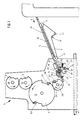
- the printing unit shown in Fig. 1, generally designated 1 comprises a plate cylinder 2, a blanket cylinder 3 and a printing cylinder 4.
- the printing cylinder 4 has double Diameter of the cylinders 2, 3 and carries two gripper systems 51, 52. It is therefore an offset printing unit.
- invention is not for application to Offset printing units limited, it can rather with everyone another type of printing unit, i.e. high-pressure or gravure printing units Find application.
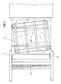
- the printing press further comprises a feed table 5, which the Sheet individually in a known, not shown Be fed in the direction of arrow a.
- a feed table 5 which the Sheet individually in a known, not shown Be fed in the direction of arrow a.
- several conveyor belts 6, 7, 8, 9 are provided, each over two deflection rollers 10, 11 and tension rollers 12, 13 run, At least one of the deflection rollers 10, 11 is driven, specifically such that the upper run of the conveyor belts in the direction of Arrow b is running.
- the conveyor belts 6 to 9 thus run underneath an acute angle to the feeding and conveying direction of the sheets, which is indicated by the arrow a.
- Deflection rollers 10, 11 with the tensioning rollers 12, 13 on a carrier 14 attached which is rotatably mounted about an axis 15 to the acute angle between the conveying direction of the bow, arrow a, and the transport direction of the conveyor belts 6 to 9, arrow b, to be able to adjust.
- a side mark 16, 17 fixed on both sides.
- the conveyor belts 6 to 9 each Bow with a transverse to the conveying direction a Movement component against the side mark 16 and cause this results in a side orientation of the sheet during its Transport. Due to the rotatable arrangement of the carrier 14 furthermore the possibility to turn the sheet against the side mark 17 to guide and align there laterally.
- One across Movement component directed in the conveying direction can also be the bow be granted in addition to in the conveying direction revolving conveyor belts or conveyor rollers blowing obliquely to it Air nozzles or an additional one running diagonally or transversely to it Conveyor belt is provided.
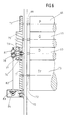
- a feed roller 18 arranged over the feed table extends over the entire width of the feed table 5.
- the feed roller 18 is wound a coil spring, one end of which is connected to a fixed part of the feed table 5, while the other end is attached to the conveyor roller 18.
- the Coil spring tends to move the feed roller 18 in the opposite direction arrow c to rotate.
- At both ends of the conveyor roller 18 is each a disc 21 is attached to which one end of a rope 22nd is connected and on which part of the rope is wound can be.
- the other end of the rope 22 is on a lever 23 attached, which is pivotable about an axis 24.
- Each lever 23 carries a roller 25, which by means of a fixed board 26th supported, with the other end engaging the lever 23 Compression spring 27 is held in contact with a control disk 28.
- the two control disks 28 are seated on a synchronous with the Machine speed driven shaft 29. Instead of this drive another can alternately accelerate the conveyor roller and decelerating drive are used.
- a pressure roller 32 is freely rotatable.
- the axis 30 is in turn controlled synchronously with the machine speed, that the pressure rollers 32 temporarily against the conveyor roller 18 pressed and temporarily lifted from this.
- Behind the Conveyor roller 18 is pivotable on the feed table in a known manner a pre-alignment token 33 stored, made up of several arranged across the width of the feed table Attacks exists.
- the diameter of the transfer drum 34 is smaller than the diameter of the plate cylinder 2 because the Transfer drum because of the delay on the Feed speed of the sheets a smaller medium Peripheral speed as the plate cylinder 2 or with has the same circumferential speed rotating printing cylinder 4, but after every half revolution of the impression cylinder 4 or one revolution of the plate cylinder 2 and one revolution the transfer drum 34 whose gripper system 49 one of the Gripper systems 50, 51 must face each other for sheet transfer.
- the Transfer drum can also be used with two gripper systems be carried out. Then their diameter increases corresponding.
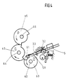
- the transfer drum 34 is firmly seated on a shaft 35 on the a pinion 36 is also fitted.
- the pinion 36 meshes with a gear 37, which together with a support plate 38 on a to the shaft 35 parallel shaft 39 is placed.
- the support disk 38 carries four carrier rollers 40 to 43.
- the carrier rollers work in pairs with the two side flanks of a raised one spatial control curve 46 together.
- the control cam 46 is on a main drive shaft 47 of the Printing machine put on.
- the main drive shaft 47 carries a bevel gear 48 per printing unit, with which downstream gears the cylinders 2 to 4 in itself known, not shown are driven.
- the ropes 22 therefore begin unwind from the disks 21 and the conveyor roller 18 in Accelerate in the direction of arrow c. At the same time it swings Control shaft 30, the lever 31 and thereby brings the pressure roller 32nd on the arch.
- the control disks 28 are now so eccentric mounted that the levers with a further rotation of the shaft 29 23 to deflect growing paths and thus the conveyor roller 18 and as a result also accelerate the bow.
- the Clamping the sheet between the conveyor roller 18 and the Pinch rollers 32 ensure that regardless of its strength and Ripple, its at the pre-alignment mark 33 aligned front edge without the risk of misalignment Transfer drum 34 is moved.
- the arch reaches the end of the feed table 5 with one Speed slightly higher than the peripheral speed the transfer drum 34 is in this moment, so runs Sheet in the open gripper system 49 and comes to System on the front mark 50. Then the grippers close of the gripper system 49. The sheet thus runs to the front mark 50 at a speed below the speed of the Sheet when printing. A rebound or a deformation of the Arch can therefore be used despite a very large one Avoid machine speed. Furthermore, his Acceptance from the feed table 5 not to fear that he sweeps the following bow.
- the transfer drum 34 is by means of the unevenly translating gear 38 to 46 accelerates until the peripheral speed of the transfer drum 34 is approximately equal to that Circumferential speed of the printing cylinder 4 is.
- the grabs pass of the gripper system 49 of the transfer drum 34 the sheet to the Gripper e.g. of the gripper system 52 of the printing cylinder 4, which with constant high speed.
- the same feed table 5 with the conveyor roller 18, the pressure rollers 32 and the pre-alignment marker 33 are used is also provided in the first embodiment.
- a pressure cylinder 60 right away behind the end of the feed table 5 is a pressure cylinder 60 a front mark 59 and a bow on this mark defining gripper system 61 is provided.
- the one on a shaft 62 seated impression cylinder 60 acts with a blanket cylinder 63 together, which sits on a shaft 64.
- the blanket cylinder 63 is in turn connected to a plate cylinder 65 on a shaft 66 employed.
- the gear 75 is still both engaged with a gear 76 that is fixed sits on the shaft 66 of the plate cylinder 65, and a gear 77, which is firmly placed on the shaft 62 and in one area 78 has no teeth.
- On the shaft 62 is still one Carried disc 79, which carries a driving roller 80.
- the driving roller 80 can have a spatial control curve 81 cooperate with a bevel gear 83 via a shaft 82 connected is.
- the bevel gear 83 meshes with one on the Main drive shaft 67 further bevel gear 84.
- Die Control curve 81 of the non-uniformly gearbox 79 to 81 is designed so that it engages the driver roller 80 takes along when the area 78 of the gear 77 on the gear 75 passes by.
- the shape of the control curve 81 is also selected so that that in this area the support disk 79 is initially delayed and then accelerated again until the support disk 79 and thus the gear 77 again the same peripheral speed as that Have gear 75. The delay takes place down to a value in the case of the pressure cylinder 60 placed on the shaft 62 Has peripheral speed that is slightly below the Feed speed of the sheet from the feed table 5 is.
- the tooth-free area begins 78 of the gear 77 opposite the gear 75 again, so that Gear 75 the shaft 62 and thus the pressure cylinder 60 no further drives.
- the driving roller 80 arrives again in the area of the control curve 81, in which it is free of play is guided so that the drive of the printing cylinder on the Control curve 81 takes place.
- Their effective area is now delayed the printing cylinder 60 in turn to a peripheral speed in the next sheet can be taken over.
- the plate cylinder 65 and the blanket cylinder 63 are also during the Acceleration and deceleration of the printing cylinder over the Gears 71, 74, 75 and 76 at machine speed driven.
- the average Circumferential speed of the impression cylinder 60 is lower than the peripheral speed of the blanket cylinder 63 or Plate cylinder 65, which are both the same size, is the Dimension the diameter of the impression cylinder accordingly smaller.
Landscapes
- Supply, Installation And Extraction Of Printed Sheets Or Plates (AREA)
- Inking, Control Or Cleaning Of Printing Machines (AREA)
- Registering Or Overturning Sheets (AREA)
- Sheets, Magazines, And Separation Thereof (AREA)
Claims (8)
- Dispositif pour transférer des feuilles à un groupe d'impression comportant au moins un cylindre porte-plaque et un cylindre de pression (2; 4) d'une rotative à feuilles, comprenant une table de marge (5) ainsi qu'un tambour de transfert (34) disposé près de la fin de la table de marge (5) et présentant au moins un taquet frontal (50) et un système de pinces (49) immobilisant les feuilles contre le taquet frontal (50), système qui coopère avec le cylindre de pression (4), portant des pinces, la table de marge (5) étant pourvue de bandes de transport (6 à 9) s'étendant en biais dans la direction du transport qui déplacent chaque feuille en lui appliquant une composante de mouvement supplémentaire, dirigée transversalement à la direction de transport vers le groupe d'impression, moyens de transport par lesquels la feuille peut être appliquée contre un taquet latéral (16, 17) fixe et des taquets frontaux d'alignement préliminaire (33), dans lequel dans l'extrémité de la table de marge (5) dirigée vers le groupe d'impression (1), on a prévu un rouleau de transport (18) s'étendant sur toute la largeur de la table de marge (5), coopérant avec des galets presseurs (32) mis de façon cadencée en et hors action, rouleau qui est entraíné au moyen d'un dispositif d'entraínement (21 à 29) produisant alternativement une accélération et une décélération et qui, pendant sa phase d'accélération, entraíne la feuille par son contact de frottement avec elle, en accélérant la feuille dans la direction de transport, en outre le tambour de transfert (34) est disposé au-dessus de l'extrémité de la table de marge (5) et entraíné, au moyen d'un mécanisme (38 à 46) à rapport de transmission variable, de manière que lors de la reprise d'une feuille, il tourne à une vitesse inférieure à la vitesse de la feuille, il soit ensuite accéléré et, lors de la délivrance de la feuille, il possède à peu près la même (4), et l'angle aigu de l'inclinaison entre la direction de transport des deux bandes de transport (6 à 9) et la direction de transport des feuilles peut être ajusté.
- Dispositif pour transférer des feuilles à un groupe d'impression comportant au moins un cylindre porte-plaque (63) et un cylindre de pression (60) d'une rotative à feuilles, comprenant une table de marge (5) dans laquelle sont prévus des bandes de transport (6 à 9) s'étendant en biais dans la direction du transport et déplaçant chaque feuille en lui conférant une composante de mouvement supplémentaire dirigée transversalement à la direction de transport vers le groupe d'impression, moyens de transport par lesquels la feuille peut être amenée contre un taquet latéral fixe (16, 17) et des taquets frontaux d'alignement préliminaire (33), en outre dans l'extrémité de la table de marge (5) dirigée vers le groupe d'impression (1), on a prévu un rouleau de transport (18) s'étendant sur toute la largeur de la table de marge (5) et, coopérant avec des galets presseurs (32) mis de façon cadencée en et hors action, rouleau qui est entraíné au moyen d'un dispositif d'entraínement (21 à 29) produisant alternativement une accélération et une décélération et qui, pendant sa phase d' accélération, entraíne la feuille par son contact de frottement avec elle, en accélérant la feuille dans la direction de transport, en outre le cylindre de pression (60) est disposé derrière la table de marge (5) et est pourvu d'au moins un taquet frontal (59) et d'un système de pinces (61) immobilisant les feuilles contre ce taquet frontal, et le cylindre de pression (60) est entraíné, avec utilisation d'un mécanisme (79 à 81) à rapport de transmission variable, de manière que, lors de la reprise d'une feuille, il tourne à une vitesse circonférentielle inférieure à la vitesse de la feuille, qu'il soit ensuite accéléré et que, pendant l'impression, il tourne à la même vitesse circonférentielle que le cylindre porte-plaque (63).
- Dispositif selon la revendication 2 caractérisé en ce que l'angle aigu de l'inclinaison entre la direction de transport des bandes de transport (6 à 9) et la direction de transport des feuilles peut être ajusté.
- Dispositif selon la revendication 1 ou 2, caractérisé en ce que le cylindre de pression (4) porte deux systèmes de pinces (51, 52) à sa périphérie.
- Dispositif selon la revendication 1, caractérisé en ce que le tambour de transfert porte deux systèmes de pinces à sa périphérie.
- Dispositif selon la revendication 1 ou 2, caractérisé en ce que le mécanisme (38 à 46; 79 à 81) à rapport de transmission variable est un mécanisme comportant une came tridimensionnelle.
- Dispositif selon la revendication 1, caractérisé en ce que le mécanisme (38 à 46) à rapport de transmission variable est conçu de manière que le transfert de la feuille au cylindre de pression (4) s'effectue à la fin de la phase d'accélération du tambour de transfert (34).
- Dispositif selon la revendication 2, caractérisé en ce que le cylindre de pression (60) est entraíné au moyen du mécanisme (79 à 81) à rapport de transmission variable dans les phases d'accélération et de décélération, ainsi que pendant la reprise de la feuille de la table de marge (3), tandis qu'il est entraíné au moyen du dispositif d'entraínement (68 à 71, 74 à 77) du cylindre porte-plaque (63) dans la phase d'impression.
Applications Claiming Priority (2)
| Application Number | Priority Date | Filing Date | Title |
|---|---|---|---|
| DE3726780 | 1987-08-12 | ||
| DE19873726780 DE3726780A1 (de) | 1987-08-12 | 1987-08-12 | Vorrichtung zur uebergabe von bogen |
Publications (4)
| Publication Number | Publication Date |
|---|---|
| EP0303053A2 EP0303053A2 (fr) | 1989-02-15 |
| EP0303053A3 EP0303053A3 (en) | 1990-04-04 |
| EP0303053B1 EP0303053B1 (fr) | 1992-09-09 |
| EP0303053B2 true EP0303053B2 (fr) | 2000-10-25 |
Family
ID=6333561
Family Applications (1)
| Application Number | Title | Priority Date | Filing Date |
|---|---|---|---|
| EP88110921A Expired - Lifetime EP0303053B2 (fr) | 1987-08-12 | 1988-07-08 | Dispositif de transfert de feuilles |
Country Status (5)
| Country | Link |
|---|---|
| US (1) | US4825762A (fr) |
| EP (1) | EP0303053B2 (fr) |
| JP (1) | JP2752381B2 (fr) |
| CA (1) | CA1287255C (fr) |
| DE (2) | DE3726780A1 (fr) |
Families Citing this family (17)
| Publication number | Priority date | Publication date | Assignee | Title |
|---|---|---|---|---|
| GB8619504D0 (en) * | 1986-08-11 | 1986-09-24 | Rockwell Graphic Systems Ltd | Accelerating drive member |
| DE4020730C2 (de) * | 1990-06-29 | 1999-04-15 | Krause Biagosch Gmbh | Verfahren und Vorrichtung zum Verbessern der Stapelqualität eines Bogenstapels |
| DE4431684C2 (de) * | 1994-09-06 | 1998-12-03 | Kba Planeta Ag | Vorrichtung zum Antreiben einer Bogenbeschleunigungseinrichtung |
| DE4431683C2 (de) * | 1994-09-06 | 1998-11-26 | Kba Planeta Ag | Antrieb einer Bogenbeschleunigungseinrichtung |
| DE4431680C2 (de) * | 1994-09-06 | 1998-11-26 | Kba Planeta Ag | Antrieb eines Bogenbeschleunigungssystems |
| DE4431682C2 (de) * | 1994-09-06 | 1998-11-26 | Kba Planeta Ag | Kurvengesteuertes Bogenbeschleunigungssystem |
| DE4435264C2 (de) * | 1994-10-01 | 2001-05-10 | Heidelberger Druckmasch Ag | Bogenniederhalter |
| US5584246A (en) * | 1995-06-09 | 1996-12-17 | Werner Kammann Maschinenfabrik Gmbh | Process and apparatus for printing on flat individual articles |
| DE19901699B4 (de) * | 1998-02-04 | 2007-11-15 | Heidelberger Druckmaschinen Ag | Verfahren und eine Vorrichtung zur Durchführung des Verfahrens zur Beseitigung von rhythmischen Passerfehlern in Rotationsdruckmaschinen |
| DE10020648A1 (de) * | 2000-04-27 | 2001-10-31 | Heidelberger Druckmasch Ag | Bogendruckmaschine |
| JP2002087635A (ja) * | 2000-09-12 | 2002-03-27 | Canon Inc | シート材搬送装置およびそれを備える記録装置、記録機構付き撮像装置 |
| DE102004019220A1 (de) * | 2004-04-21 | 2005-11-10 | Koenig & Bauer Ag | Vorrichtung zum Zuführen von Bogen |
| JP2006124175A (ja) * | 2004-10-14 | 2006-05-18 | Graphic Management Associates Inc | 加速装置及び減速装置を備えた製品フィーダ |
| DE102004057842A1 (de) * | 2004-12-01 | 2006-06-08 | Koenig & Bauer Ag | Einrichtung zum Beeinflussen von Bogen |
| JP5838128B2 (ja) * | 2012-05-31 | 2015-12-24 | 株式会社木田鉄工所 | 搬送装置 |
| CN103144424B (zh) * | 2013-03-07 | 2016-01-20 | 天津长荣印刷设备股份有限公司 | 一种电子套准系统及其工作方法 |
| EP3386767A4 (fr) * | 2015-12-09 | 2019-07-31 | Hewlett-Packard Development Company, L.P. | Repérage de supports d'impression au moyen d'une pince d'extraction |
Family Cites Families (25)
| Publication number | Priority date | Publication date | Assignee | Title |
|---|---|---|---|---|
| US2335954A (en) * | 1938-09-16 | 1943-12-07 | Ditto Inc | Duplicating machine |
| US2687886A (en) * | 1950-10-21 | 1954-08-31 | Alphonse W Pitner | Registering apparatus for printing machines |
| US2708405A (en) * | 1951-08-17 | 1955-05-17 | Miller Printing Machinery Co | Printing press feed and registering mechanism |
| GB1187254A (en) * | 1967-09-26 | 1970-04-08 | Gestetner Ltd | Offset Printing Apparatus |
| US3858508A (en) * | 1969-09-15 | 1975-01-07 | Ricoh Kk | Offset printing machine |
| DE2062503A1 (de) * | 1970-12-18 | 1972-06-22 | Koenig & Bauer Schnellpressfab | Bogenzuführung bei Druckmaschinen |
| IT991860B (it) * | 1973-07-25 | 1975-08-30 | Nebiolo Spa | Macchina rotativa da stampa per fogli singoli |
| SE375511B (fr) * | 1973-08-13 | 1975-04-21 | Svecia Silkscreen Maskiner Ab | |
| DE2449629A1 (de) * | 1974-10-18 | 1976-04-29 | Maschf Augsburg Nuernberg Ag | Bogenanlegevorrichtung fuer rotationsdruckmaschinen |
| DE2452051A1 (de) * | 1974-11-02 | 1976-05-06 | Maschf Augsburg Nuernberg Ag | Vorrichtung zum passergerechten anlegen von bogen in bogenrotationsdruckmaschinen |
| US3954494A (en) * | 1974-12-30 | 1976-05-04 | Chevron Research Company | Wax-flux composition containing a succinimide salt of an alkylaryl sulfonic acid for soldering |
| DD126254A1 (fr) * | 1976-06-18 | 1977-07-06 | ||
| DE7713720U1 (de) * | 1977-04-30 | 1979-04-05 | Raes, Karl, 6201 Wildsachsen | Druckwerk einer bogendruckmaschine |
| DE2720675C2 (de) * | 1977-05-07 | 1982-09-02 | M.A.N. Maschinenfabrik Augsburg-Nürnberg AG, 8900 Augsburg | Bogenzufuhreinrichtung für eine Rotations-Druckmaschine |
| DE2744925C2 (de) * | 1977-10-06 | 1986-06-12 | Koenig & Bauer AG, 8700 Würzburg | Einrichtung auf einer Stopptrommel für eine Bogenrotationsdruckmaschine |
| DD142694A1 (de) * | 1979-04-02 | 1980-07-09 | Guenter Weisbach | Bogenrotationsdruckmaschine mit einem von unten arbeitenden vorgreifer |
| JPS57136744U (fr) * | 1981-02-20 | 1982-08-26 | ||
| DE3108808C2 (de) * | 1981-03-07 | 1985-02-21 | M.A.N.- Roland Druckmaschinen AG, 6050 Offenbach | Bogen-Rotations-Flachdruckmaschine |
| JPS57197164A (en) * | 1981-05-30 | 1982-12-03 | Komori Printing Mach Co Ltd | Monochromatic sheet-fed off-set press |
| JPS5862643U (ja) * | 1981-10-22 | 1983-04-27 | 三菱重工業株式会社 | 印刷機の給紙胴駆動装置 |
| DE3318117A1 (de) * | 1982-05-20 | 1983-11-24 | International Standard Electric Corp., 10022 New York, N.Y. | Blattausrichtvorrichtung |
| JPS58181536U (ja) * | 1982-05-31 | 1983-12-03 | リョービ株式会社 | 両面印刷機の給紙装置 |
| GB2166419B (en) * | 1984-09-28 | 1988-05-05 | Rotaprint Plc | Sheet registration device and method |
| DE3511897A1 (de) * | 1985-04-01 | 1986-10-09 | Mabeg Maschinenbau Gmbh Nachf. Hense & Pleines Gmbh & Co, 6050 Offenbach | Vorrichtung zum seitlichen ausrichten von bogen |
| DE8514775U1 (de) * | 1985-05-20 | 1985-06-27 | Heidelberger Druckmaschinen Ag, 6900 Heidelberg | Antrieb für einen Bogentransportmechanismus am Anleger einer Rotationsdruckmaschine |
-
1987
- 1987-08-12 DE DE19873726780 patent/DE3726780A1/de not_active Withdrawn
-
1988
- 1988-07-08 DE DE8888110921T patent/DE3874459D1/de not_active Expired - Lifetime
- 1988-07-08 EP EP88110921A patent/EP0303053B2/fr not_active Expired - Lifetime
- 1988-08-02 US US07/227,368 patent/US4825762A/en not_active Expired - Fee Related
- 1988-08-09 CA CA000574216A patent/CA1287255C/fr not_active Expired - Lifetime
- 1988-08-09 JP JP63197307A patent/JP2752381B2/ja not_active Expired - Fee Related
Also Published As
| Publication number | Publication date |
|---|---|
| DE3874459D1 (de) | 1992-10-15 |
| US4825762A (en) | 1989-05-02 |
| JPS6469344A (en) | 1989-03-15 |
| JP2752381B2 (ja) | 1998-05-18 |
| EP0303053B1 (fr) | 1992-09-09 |
| EP0303053A2 (fr) | 1989-02-15 |
| DE3726780A1 (de) | 1989-02-23 |
| CA1287255C (fr) | 1991-08-06 |
| EP0303053A3 (en) | 1990-04-04 |
Similar Documents
| Publication | Publication Date | Title |
|---|---|---|
| EP0303053B2 (fr) | Dispositif de transfert de feuilles | |
| DE2435665A1 (de) | Rotationsdruckmaschine | |
| EP0059873B1 (fr) | Dispositif de prélèvement d'imprimés des disques de réception d'un appareil de pliage | |
| DE10047395B4 (de) | Transportsystem für flache Produkte | |
| EP0498068A1 (fr) | Plieuse, dans laquelle le transport d'exemplaires pliés est realisé en passant par des moyens de transport, des galets partiels et des cordons | |
| EP1479627B1 (fr) | Dispositif d'alignement de feuilles | |
| DE19620938A1 (de) | Vorrichtung und Verfahren zum abschmierfreien Ablegen von Druckbogen auf einen Stapel | |
| EP0429884A1 (fr) | Plieuse pour machine d'impression | |
| DE69024857T2 (de) | Bogenzuführung | |
| DE2750792B2 (de) | Falzapparat | |
| EP1209111A2 (fr) | Dispositif pour déposer des feuilles | |
| DE3230846C2 (de) | Vorrichtung zum Fördern von Bogen oder Bogenpaketen | |
| DE19957574C2 (de) | Vorrichtung zum Ablegen von Bogen auf einen Stapel | |
| EP0405107A1 (fr) | Dispositif pour déliasser des feuilles de papier empilées | |
| DE1923625C3 (de) | Vorrichtung zur Zuführung von Bogen für eine Bogen-Rotationsdruckmaschine | |
| DE2810874C2 (de) | Vorrichtung zum Steuern des Öffnungszeitpunktes der Greifer eines Bodenauslegers | |
| DE3305219C2 (fr) | ||
| EP0241663B1 (fr) | Dispositif pour convoyer et tourner des feuilles pour machines traitant des feuilles | |
| DE3107807C2 (de) | Bogenbeschleunigungsvorrichtung | |
| DE3629080C2 (fr) | ||
| DE2624170C3 (de) | Seitenausrichtvorrichtung | |
| DE3401819A1 (de) | Beschickungsvorrichtung fuer eine mit einer kontinuierlich arbeitenden einzugseinrichtung versehene bogenverarbeitungsmaschine | |
| DE3332809C2 (de) | Bandverzögerungsstrecke für einen Falzapparat | |
| EP0365847A2 (fr) | Dispositif ralentisseur de sortie pour une machine pour imprimer des feuilles | |
| DE1913844C3 (de) | Antriebsvorrichtung einer rotie renden Vorgreifertrommel mit Vorgreifern zur Anlage von Bogen an einem Zylinder |
Legal Events
| Date | Code | Title | Description |
|---|---|---|---|
| PUAI | Public reference made under article 153(3) epc to a published international application that has entered the european phase |
Free format text: ORIGINAL CODE: 0009012 |
|
| AK | Designated contracting states |
Kind code of ref document: A2 Designated state(s): CH DE FR GB IT LI NL SE |
|
| PUAL | Search report despatched |
Free format text: ORIGINAL CODE: 0009013 |
|
| AK | Designated contracting states |
Kind code of ref document: A3 Designated state(s): CH DE FR GB IT LI NL SE |
|
| 17P | Request for examination filed |
Effective date: 19900321 |
|
| 17Q | First examination report despatched |
Effective date: 19910903 |
|
| GRAA | (expected) grant |
Free format text: ORIGINAL CODE: 0009210 |
|
| AK | Designated contracting states |
Kind code of ref document: B1 Designated state(s): CH DE FR GB IT LI NL SE |
|
| ITF | It: translation for a ep patent filed | ||
| REF | Corresponds to: |
Ref document number: 3874459 Country of ref document: DE Date of ref document: 19921015 |
|
| ET | Fr: translation filed | ||
| GBT | Gb: translation of ep patent filed (gb section 77(6)(a)/1977) |
Effective date: 19921201 |
|
| PLBI | Opposition filed |
Free format text: ORIGINAL CODE: 0009260 |
|
| PLBI | Opposition filed |
Free format text: ORIGINAL CODE: 0009260 |
|
| 26 | Opposition filed |
Opponent name: KBA-PLANETA AG Effective date: 19930608 |
|
| 26 | Opposition filed |
Opponent name: KOENIG & BAUER AKTIENGESELLSCHAFT Effective date: 19930609 Opponent name: KBA-PLANETA AG Effective date: 19930608 |
|
| NLR1 | Nl: opposition has been filed with the epo |
Opponent name: KBA-PLANETA AG |
|
| EAL | Se: european patent in force in sweden |
Ref document number: 88110921.9 |
|
| PLAB | Opposition data, opponent's data or that of the opponent's representative modified |
Free format text: ORIGINAL CODE: 0009299OPPO |
|
| R26 | Opposition filed (corrected) |
Opponent name: KBA - PLANETA AG * 930609 KOENIG & BAUER AKTIENGES Effective date: 19930608 |
|
| PLAW | Interlocutory decision in opposition |
Free format text: ORIGINAL CODE: EPIDOS IDOP |
|
| APAE | Appeal reference modified |
Free format text: ORIGINAL CODE: EPIDOS REFNO |
|
| APAC | Appeal dossier modified |
Free format text: ORIGINAL CODE: EPIDOS NOAPO |
|
| APAC | Appeal dossier modified |
Free format text: ORIGINAL CODE: EPIDOS NOAPO |
|
| PLBQ | Unpublished change to opponent data |
Free format text: ORIGINAL CODE: EPIDOS OPPO |
|
| PLAB | Opposition data, opponent's data or that of the opponent's representative modified |
Free format text: ORIGINAL CODE: 0009299OPPO |
|
| R26 | Opposition filed (corrected) |
Opponent name: KOENIG & BAUER AKTIENGESELLSCHAFT * 19930609 KOENI Effective date: 19930608 |
|
| APAC | Appeal dossier modified |
Free format text: ORIGINAL CODE: EPIDOS NOAPO |
|
| NLR1 | Nl: opposition has been filed with the epo |
Opponent name: KOENIG & BAUER AKTIENGESELLSCHAFT |
|
| PLBQ | Unpublished change to opponent data |
Free format text: ORIGINAL CODE: EPIDOS OPPO |
|
| PLAW | Interlocutory decision in opposition |
Free format text: ORIGINAL CODE: EPIDOS IDOP |
|
| PLAB | Opposition data, opponent's data or that of the opponent's representative modified |
Free format text: ORIGINAL CODE: 0009299OPPO |
|
| R26 | Opposition filed (corrected) |
Opponent name: KOENIG & BAUER AKTIENGESELLSCHAFT * 19930609 KOENI Effective date: 19930608 |
|
| PUAH | Patent maintained in amended form |
Free format text: ORIGINAL CODE: 0009272 |
|
| STAA | Information on the status of an ep patent application or granted ep patent |
Free format text: STATUS: PATENT MAINTAINED AS AMENDED |
|
| NLR1 | Nl: opposition has been filed with the epo |
Opponent name: KOENIG & BAUER AKTIENGESELLSCHAFT |
|
| ITF | It: translation for a ep patent filed | ||
| 27A | Patent maintained in amended form |
Effective date: 20001025 |
|
| AK | Designated contracting states |
Kind code of ref document: B2 Designated state(s): CH DE FR GB IT LI NL SE |
|
| REG | Reference to a national code |
Ref country code: CH Ref legal event code: AEN Free format text: AUFRECHTERHALTUNG DES PATENTES IN GEAENDERTER FORM |
|
| NLR2 | Nl: decision of opposition | ||
| ET3 | Fr: translation filed ** decision concerning opposition | ||
| GBTA | Gb: translation of amended ep patent filed (gb section 77(6)(b)/1977) | ||
| NLR3 | Nl: receipt of modified translations in the netherlands language after an opposition procedure | ||
| REG | Reference to a national code |
Ref country code: GB Ref legal event code: IF02 |
|
| PGFP | Annual fee paid to national office [announced via postgrant information from national office to epo] |
Ref country code: CH Payment date: 20020619 Year of fee payment: 15 |
|
| PGFP | Annual fee paid to national office [announced via postgrant information from national office to epo] |
Ref country code: SE Payment date: 20020625 Year of fee payment: 15 Ref country code: NL Payment date: 20020625 Year of fee payment: 15 |
|
| PGFP | Annual fee paid to national office [announced via postgrant information from national office to epo] |
Ref country code: GB Payment date: 20020628 Year of fee payment: 15 |
|
| PGFP | Annual fee paid to national office [announced via postgrant information from national office to epo] |
Ref country code: FR Payment date: 20020711 Year of fee payment: 15 Ref country code: DE Payment date: 20020711 Year of fee payment: 15 |
|
| PG25 | Lapsed in a contracting state [announced via postgrant information from national office to epo] |
Ref country code: GB Free format text: LAPSE BECAUSE OF NON-PAYMENT OF DUE FEES Effective date: 20030708 |
|
| PG25 | Lapsed in a contracting state [announced via postgrant information from national office to epo] |
Ref country code: SE Free format text: LAPSE BECAUSE OF NON-PAYMENT OF DUE FEES Effective date: 20030709 |
|
| PG25 | Lapsed in a contracting state [announced via postgrant information from national office to epo] |
Ref country code: LI Free format text: LAPSE BECAUSE OF NON-PAYMENT OF DUE FEES Effective date: 20030731 Ref country code: CH Free format text: LAPSE BECAUSE OF NON-PAYMENT OF DUE FEES Effective date: 20030731 |
|
| PG25 | Lapsed in a contracting state [announced via postgrant information from national office to epo] |
Ref country code: NL Free format text: LAPSE BECAUSE OF NON-PAYMENT OF DUE FEES Effective date: 20040201 |
|
| PG25 | Lapsed in a contracting state [announced via postgrant information from national office to epo] |
Ref country code: DE Free format text: LAPSE BECAUSE OF NON-PAYMENT OF DUE FEES Effective date: 20040203 |
|
| GBPC | Gb: european patent ceased through non-payment of renewal fee |
Effective date: 20030708 |
|
| EUG | Se: european patent has lapsed | ||
| REG | Reference to a national code |
Ref country code: CH Ref legal event code: PL |
|
| PG25 | Lapsed in a contracting state [announced via postgrant information from national office to epo] |
Ref country code: FR Free format text: LAPSE BECAUSE OF NON-PAYMENT OF DUE FEES Effective date: 20040331 |
|
| NLV4 | Nl: lapsed or anulled due to non-payment of the annual fee |
Effective date: 20040201 |
|
| REG | Reference to a national code |
Ref country code: FR Ref legal event code: ST |
|
| PG25 | Lapsed in a contracting state [announced via postgrant information from national office to epo] |
Ref country code: IT Free format text: LAPSE BECAUSE OF NON-PAYMENT OF DUE FEES;WARNING: LAPSES OF ITALIAN PATENTS WITH EFFECTIVE DATE BEFORE 2007 MAY HAVE OCCURRED AT ANY TIME BEFORE 2007. THE CORRECT EFFECTIVE DATE MAY BE DIFFERENT FROM THE ONE RECORDED. Effective date: 20050708 |
|
| APAH | Appeal reference modified |
Free format text: ORIGINAL CODE: EPIDOSCREFNO |