EP0303707A1 - Procede de mesure optique et dispositif utilise a cet effet dans un analyseur automatique - Google Patents
Procede de mesure optique et dispositif utilise a cet effet dans un analyseur automatique Download PDFInfo
- Publication number
- EP0303707A1 EP0303707A1 EP88901914A EP88901914A EP0303707A1 EP 0303707 A1 EP0303707 A1 EP 0303707A1 EP 88901914 A EP88901914 A EP 88901914A EP 88901914 A EP88901914 A EP 88901914A EP 0303707 A1 EP0303707 A1 EP 0303707A1
- Authority
- EP
- European Patent Office
- Prior art keywords
- light
- optical
- optical measurement
- reaction
- measured
- Prior art date
- Legal status (The legal status is an assumption and is not a legal conclusion. Google has not performed a legal analysis and makes no representation as to the accuracy of the status listed.)
- Withdrawn
Links
Images



Classifications
-
- G—PHYSICS
- G01—MEASURING; TESTING
- G01N—INVESTIGATING OR ANALYSING MATERIALS BY DETERMINING THEIR CHEMICAL OR PHYSICAL PROPERTIES
- G01N21/00—Investigating or analysing materials by the use of optical means, i.e. using sub-millimetre waves, infrared, visible or ultraviolet light
- G01N21/17—Systems in which incident light is modified in accordance with the properties of the material investigated
- G01N21/25—Colour; Spectral properties, i.e. comparison of effect of material on the light at two or more different wavelengths or wavelength bands
- G01N21/251—Colorimeters; Construction thereof
- G01N21/253—Colorimeters; Construction thereof for batch operation, i.e. multisample apparatus
-
- G—PHYSICS
- G01—MEASURING; TESTING
- G01N—INVESTIGATING OR ANALYSING MATERIALS BY DETERMINING THEIR CHEMICAL OR PHYSICAL PROPERTIES
- G01N35/00—Automatic analysis not limited to methods or materials provided for in any single one of groups G01N1/00 - G01N33/00; Handling materials therefor
- G01N35/02—Automatic analysis not limited to methods or materials provided for in any single one of groups G01N1/00 - G01N33/00; Handling materials therefor using a plurality of sample containers moved by a conveyor system past one or more treatment or analysis stations
- G01N35/025—Automatic analysis not limited to methods or materials provided for in any single one of groups G01N1/00 - G01N33/00; Handling materials therefor using a plurality of sample containers moved by a conveyor system past one or more treatment or analysis stations having a carousel or turntable for reaction cells or cuvettes
-
- G—PHYSICS
- G01—MEASURING; TESTING
- G01J—MEASUREMENT OF INTENSITY, VELOCITY, SPECTRAL CONTENT, POLARISATION, PHASE OR PULSE CHARACTERISTICS OF INFRARED, VISIBLE OR ULTRAVIOLET LIGHT; COLORIMETRY; RADIATION PYROMETRY
- G01J3/00—Spectrometry; Spectrophotometry; Monochromators; Measuring colours
- G01J3/12—Generating the spectrum; Monochromators
- G01J3/18—Generating the spectrum; Monochromators using diffraction elements, e.g. grating
-
- G—PHYSICS
- G01—MEASURING; TESTING
- G01N—INVESTIGATING OR ANALYSING MATERIALS BY DETERMINING THEIR CHEMICAL OR PHYSICAL PROPERTIES
- G01N21/00—Investigating or analysing materials by the use of optical means, i.e. using sub-millimetre waves, infrared, visible or ultraviolet light
- G01N21/17—Systems in which incident light is modified in accordance with the properties of the material investigated
- G01N21/25—Colour; Spectral properties, i.e. comparison of effect of material on the light at two or more different wavelengths or wavelength bands
- G01N21/31—Investigating relative effect of material at wavelengths characteristic of specific elements or molecules, e.g. atomic absorption spectrometry
- G01N2021/3129—Determining multicomponents by multiwavelength light
- G01N2021/3133—Determining multicomponents by multiwavelength light with selection of wavelengths before the sample
-
- G—PHYSICS
- G01—MEASURING; TESTING
- G01N—INVESTIGATING OR ANALYSING MATERIALS BY DETERMINING THEIR CHEMICAL OR PHYSICAL PROPERTIES
- G01N35/00—Automatic analysis not limited to methods or materials provided for in any single one of groups G01N1/00 - G01N33/00; Handling materials therefor
- G01N35/02—Automatic analysis not limited to methods or materials provided for in any single one of groups G01N1/00 - G01N33/00; Handling materials therefor using a plurality of sample containers moved by a conveyor system past one or more treatment or analysis stations
- G01N35/04—Details of the conveyor system
- G01N2035/0439—Rotary sample carriers, i.e. carousels
- G01N2035/0444—Rotary sample carriers, i.e. carousels for cuvettes or reaction vessels
-
- G—PHYSICS
- G01—MEASURING; TESTING
- G01N—INVESTIGATING OR ANALYSING MATERIALS BY DETERMINING THEIR CHEMICAL OR PHYSICAL PROPERTIES
- G01N21/00—Investigating or analysing materials by the use of optical means, i.e. using sub-millimetre waves, infrared, visible or ultraviolet light
- G01N21/75—Systems in which material is subjected to a chemical reaction, the progress or the result of the reaction being investigated
-
- G—PHYSICS
- G01—MEASURING; TESTING
- G01N—INVESTIGATING OR ANALYSING MATERIALS BY DETERMINING THEIR CHEMICAL OR PHYSICAL PROPERTIES
- G01N2201/00—Features of devices classified in G01N21/00
- G01N2201/04—Batch operation; multisample devices
- G01N2201/0415—Carrusel, sequential
Definitions
- the present invention relates to a method and apparatus for optical measurement suitable for automatic analysis apparatus for performing biochemical analysis and immunological analysis and in particular to a quite novel method and apparatus for optical measurement dependent upon a so-called pre-spectrophotometric system.
- the pre-spectrophotometric system depends on the principle that light to be measured is converted to the single wavelength light corre-sponding to the test item by means of a filter before a reaction vessel containing a reaction solution (which here-inafter refers to a solution in which a reagent correspond-ing to the specimen and test items) has reached a position for optical measurement whereby the absorbance is determined.
- a reaction vessel containing a reaction solution which here-inafter refers to a solution in which a reagent correspond-ing to the specimen and test items
- the optical measurement by means of the conventional pre-spectrophotometric system has problems in that the number of filters restricts the test items and the time-course variation in the filter may deteriorate the precision of measurements.
- the optical measurement by means of the post-spectrophotometric system is based on the principle that a reaction vessel which has arrived a optical measurement position is irradiated with full wavelength light to be measured when the reaction vessel holded by a rotating reaction vessel holder traverses the position whereby the transmitted light is divided into a spectrum by means of a grating (a light disperser) to measure the absorbance of a necessary wavelength.
- a grating a light disperser
- the advantages of the optical measurement of the post-spectrophotometric system are high-speed measurability of the conditions of the chemical reactions of all the reaction solutions retained by a reaction vessel holder, measurability of the time-course of the respective reaction solutions, and correctability of the time-course variation in the brightness of the light source in measurement and the blank value of the transmitted light passing through the reaction vessel by means of two-wavelength measurement, resulting in very high reliability about measurement precision.
- a photolytic reaction may be brought about by a wavelength other than the wavelength to be measured because of some components of allergic specimen and reagents on account of the full wavelength light irradiated with the reaction solution, resulting in a fatal problem of the development of the scattering of measurements between the respective reaction solutions and the concomitant unreliability about the measurement precision.
- the conventional post-spectrophotometric method has also a problem of the limited width of a receiving element for receiving light of the respective wavelengths divided by gratings, rendering the selection of light having a wavelength near and smaller than the width impossible.
- the above post-spectrophotometric method has required very complicated apparatus and control and the resultant expensive apparatus because optical current/voltage converter circuits according to the number of the wavelengths to be measured, e.g., 12 circuits for 12-wavelengths are needed for measurement, on account of the light to be measured which transmits the reaction vessel does not have a single wavelength.
- the present invention is proposed in view of the above circumstances.
- the first object of the present invention is to apply a pre-spectrophotometric system other than the filter system, the former system which produces no photolysis because of any light of a wavelength other than the light of the wavelength to be measured, to a method for optical measurement in an automatic analysis apparatus.
- the second object of the present invention is to ensure the correctability of the difference of the transmitted light caused by the time-course variation in the brightness of the light source and against a reaction vessel.
- the third object of the present invention is to provide a method for optical measurement in a quite novel automatic analysis apparatus having only the advantages of both a so-called pre-spectrophotometric system and a post-spectrophotometric system in which the optical measurement device is greatly simplified for enabling reduction of the costs thereby being capable of substantial improvement in reliability about the measurement precision, continuous measurement can be performed by light of all wavelengths, and the measurement speed is not different from conventional optical measurement based on the post-spectrophotometric system.
- the present invention is characterized in that a reaction vessel holder holding a desired number of reaction vessels is rotated, the light to be measured is converted to light of a single wavelength according to the test item by means of a grating subjected to reciprocating pivotal rotation-derived control through the intermediary of rotation means on the promise that the optical measurement of the automatic analysis apparatus is so constructed as to optically measure the state of the chemical reactions of the specimen and the reagent in the respective reaction vessels at positions at which optical measurement is performed, and the optical transmittances of the air layer and the reaction solution are optically measured by the light of the single wavelength.
- the present invention is characterized in that, in the optical measurement device of an automatic analysis apparatus provided with a reaction vessel holder containing a desired number of reaction vessels, driving means for rotating the reaction vessel holder, and an optical measurement device for measuring the absorbances of the reaction vessels which traverse the optically measuring position by the rotation of the reaction vessel holder, the light to be measured of the optical measurement device is divided into a light of a single wavelength according to the test item, before irradiation of the reaction vessels, by means of a grating subjected to a reciprocating pivotal rotation-derived control because of rotation means; and the air layer and the reaction vessels are irradiated with the selected single wavelength light to compare the optical transmittance of the air layer with that of the reaction solution thereby performing colorimetric, optical measurement.
- the automatic analysis apparatus A in described in the embodiment is composed of a reaction vessel holder 2 containing 40 reaction vessels 1 in the form of a bottomed quadrangular prism, a pulse motor 3 for rotatably transferring the reaction vessel holder 2 at an angle corresponding to 39 containers counterclockwise with respect to Fig.
- a specimen pipet for withdrawing an aliquot of a specimen from the inside of the specimen container 5 of a sampler 4 and then delivering into the reaction vessel 1 at a specimen dividing position a
- a reagent pipet 8 for withdrawing an aliquot of a reagent corresponding to the test item from the inside of the reagent container 7 and then delivering into the reaction vessel 1 at a reagent dividing position
- an optical measurement device 9 dispose in an optical measurement position C
- a cleaning device 10 for discharging and cleaning reaction solution which completed optical measurement.
- the reaction vessel holder 2 is so constructed that the reaction vessel 1 into which a desired quantity of the s p e-cimen is placed by the pulse motor 3 at the specimen dividing position a is rotatably transferred by 351° (corre- sponding to 39 containers) counterclockwise with regard to Fig. 1, as described above, and consequently the reaction vessel 1 is intermittently transferred for every container clockwise with regard to Fig. 1.
- the present invention may be applied to an automatic analysis apparatus which is so constructed as to rotatably transfer the reaction vessel 1 by 369° (corresponding to 41 containers) clockwise with respect to Fig. 1.
- a horizontally piercing light-transmiting hole 12 is provided between the respective reaction vessels-holding holes 11 and 11 of the reaction vessel holder.
- reaction vessels-holding holes 11 are, of course, provided with horizontally pierced measurement holes 14 and 14 which transmits light to be measured.
- the pulse motor 3 for rotating the reaction vessel holder 2 thus constructed is drivingly controlled, at a constant speed, by a driver circuit 15 and a motor control circuit 16 operated by a control device CPU and the direction and angle of rotation are accurately controlled by an encoder 17 and an encoder control circuit 18 for performing high-speed positioning control.
- the pulse motor 3 may, of course, be substituted for a servo motor.
- the optical measurement device 9 is, as shown in Fig. 1, composed of a light source 20, a monochrometer 21, and a light-receiving element 22 and the grating 23 of the monochrometer 21 is so constructed as to perform reciprocating rotation at a definite timing in the range of a definite angle by means of the pulse motor 24.
- the full wavelength light irradiated from the light source 20 is condensed by a group of lenses 25 and then irradiated from the incidence slit 26 of the monochrometer 21 to the grating 23, which is so constructed as to apply only the light to be measured, reflected at an angle which reflects the single wavelength light corresponding to the test item, from a reflection slit 27 to the light-receiving element 22.
- the single wavelength light applied to the light-receiving element 22 is, as shown in Fig. 2, applied specially to an optical current/voltage converter circuit 36 and then applied to either one of two or more (four in the embodiment) of amplifiers 37 which amplify the grouped wavelength light for every wavelength to be measured thereby being amplified to a predetermined voltage.
- the measuring voltage valve amplified by the amplifier 37 is then applied to an LOG converter 40 from and A/D converter 39 via a multiplexer 38 and subjected to necessary calculation processing by the control device CPU thereafter.
- the one or more group may saffice in the present invention.
- grouping may be made according to the magnitude of the absorbance.
- light in wavelength regions at 340 to 380 nm, 410 to 500 nm, 500 to 600 nm, and 600 to 750 nm is amplified by amplifiers 37a, 37b, 37c, and 37d, respectively, and is then selected by the multiplexer 38.
- Such a process is desirable in view of resolution.
- the output of the amplifier 37 is composed by a 16-bit A/D converter 39, variation of about ).15 m V absorbance can be detected for every group when Liquot quantity of 100% is made 10 V, so that very reliable measurement data can be obtained.
- the pulse motor 24 for rotating the grating 23 is subjected to reciprocal, rotational control at a constant speed by means of a driver circuit 28 and a motor control circuit 29 operated by the control device CPU and the direction and the angle of rotation thereof is accurately controlled by an encoder 30 and an encoder control circuit 31 for performing high-speed positioning control.
- codes 32, 33, 34, and 35 denote a receiving key, a CRT, a memory circuit, and a printer, respectively.
- the wavelength switching control corresponding to the switch wavelength of the grating 23 may, as is given in Fig. 5, be performed within t 2 m sec.
- the needed wavelength light is about 340 to 750 nm in a biochemical automatic analysis apparatus, light in the maximal wavelength of 410 nm which is divided by the grating 23 into spectrum may suffice the purpose.
- the angles a and ⁇ of the necessary wavelength removed from the reflection slit 27 are calculated by the equation where : wavelength.(nm); n: the number of degrees; n: the number of grooves per 1 mm; a: incident angle; and S: reflection angle. Based on the results of the calculation, the rotational speed of the pulse motor 24 may be controlled and the encoder 29 may perform positioning control.
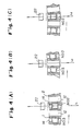
- rinsing water is placed in a reaction vessel No. 3 in which the reaction solution is to be contained at the final stage in a cleaning device 10. It is regarded as the optical measurement of a reaction vessel No. 2 being performed at the optical measurement position.
- the reaction vessel No. 3 in which the rinsing water is placed is, as given in Fig. 4 (b), transferred counterclockwise.
- the optical measurement 9 measures the transmittance (T 3B ) of light which transmitted the light-transmitting holes 12 before the reaction vessel No. 3 has approached the optical measurement position C and then measures, as given in Fig. 4 (c), the optical transmittance (T' 3B ) when the reaction vessel No. 3 has passed the optical measurement position C. Based on both optical transmittances, the absorbance of the blank of the reaction vessel OD 3B immediately before measurement for the reaction vessel No. 3 is obtained by the following equation and caused to memorize in the control circuit CPU.
- the absorbance OD 30 is expressed by
- the absorbance of the standard substance OD ns is measured by the wavelength of light ⁇ l corresponding to the test item and can be obtained by
- the value of the chemical reaction (the measurements of the reaction solution is then obtained, and the measurements are applied to the control device CPU, memorized, and finally printed by a printer and the like.
- the single wavelength measurement of the reaction solution involves very difficult correction of the time-course variation in the brightness of the light source (the intensity of wavelength) and the difference of optical transmittances among the reaction vessels as compared with the optical method of two-wavelength measurement.
- the present invention is so constructed as to correct the optical transmittances among the reaction vessels by correcting the actual measurements of the reaction solution on the basis of the absorbance of a reaction vessel containing cleaning water (T' 3B ) to obtain the absorbance of the air layer (T 3B ) thereby correcting the time-course variation in the brightness of the light source (wavelength intensity) to maintain reliability about measurement precision.
- the method for optical measurement in the automatic analysis apparatus in the present invention is composed as described above, photolysis caused by transmission of light of a wavelength other than that to be measured found in a so-called post-spectrophotometric system can completely avoided by a so-called pre-spectrophotometric method whereby reliability about measurement precision can be improved to a great extent.
- the difference of transmitted light for every reaction vessel can be corrected by measuring the pre-measurement of the optical transmittance of a reaction vessel containing clean water at the single wavelength corresponding to the test item before the measurement of the state of chemical reactions at a position of optical measurement.
- the present invention which adops a so-called pre-spectrophotometric system, only one optical current/voltage converter circuit may suffice because the light to be measured which transmits the reaction vessels is single wavelength light, so that the present invention displays much excellent effectiveness such as wide range simplification of optical measurement devices.
Landscapes
- Physics & Mathematics (AREA)
- Chemical & Material Sciences (AREA)
- General Physics & Mathematics (AREA)
- Immunology (AREA)
- Life Sciences & Earth Sciences (AREA)
- Analytical Chemistry (AREA)
- Biochemistry (AREA)
- General Health & Medical Sciences (AREA)
- Pathology (AREA)
- Health & Medical Sciences (AREA)
- Chemical Kinetics & Catalysis (AREA)
- Engineering & Computer Science (AREA)
- Plasma & Fusion (AREA)
- Spectroscopy & Molecular Physics (AREA)
- Automatic Analysis And Handling Materials Therefor (AREA)
- Investigating Or Analysing Materials By Optical Means (AREA)
- Investigating Or Analysing Materials By The Use Of Chemical Reactions (AREA)
Abstract
Procédé de mesure optique utilisant un analyseur automatique (A) pour exécuter des analyses biochimiques et des analyses immunologiques, consistant à faire tourner pas à pas un support de tube de réaction (2) contenant un nombre prédéterminé de tubes de réaction (1) et à mesurer optiquement l'état de la réaction chimique entre un échantillon et un réactif à l'intérieur de chaque tube de réaction (1) dans une position de mesure optique (C). La présente invention permet de convertir la lumière mesurée (lambda en une lumière ne présentant qu'une longueur d'onde correspondant à l'article à mesurer, à l'aide d'un grillage (23) commandé par un organe de rotation (24) qui lui imprime un mouvement alternatif et rotatif. Le coefficient de transmission optique de la couche d'air et de la solution de réaction est mesuré optiquement à l'aide de cette lumière ne présentant qu'une longueur d'onde en utilisant ce que l'on appelle un "système pré-spectral". Ce "système pré-spectral" représente le procédé qui permet de convertir à l'aide d'un filtre la lumière de mesure en une lumière ne présentant qu'une longueur d'onde correspondant à l'article à mesurer, et qui rayonne cette lumière avant que le tube de réaction contenant la solution de réaction (la solution dans un état où l'échantillon et le réactif correspondant à l'article à mesurer subissent une réaction chimique) n'atteigne la position de mesure optique, afin d'en mesurer le coefficient d'absorption.
Applications Claiming Priority (4)
| Application Number | Priority Date | Filing Date | Title |
|---|---|---|---|
| JP3587787 | 1987-02-20 | ||
| JP35877/87 | 1987-02-20 | ||
| JP323774/87 | 1987-12-23 | ||
| JP62-323774A JPH01451A (ja) | 1987-02-20 | 1987-12-23 | 自動分析装置における光学測定方法及びその装置 |
Publications (2)
| Publication Number | Publication Date |
|---|---|
| EP0303707A1 true EP0303707A1 (fr) | 1989-02-22 |
| EP0303707A4 EP0303707A4 (fr) | 1990-05-14 |
Family
ID=26374883
Family Applications (1)
| Application Number | Title | Priority Date | Filing Date |
|---|---|---|---|
| EP19880901914 Withdrawn EP0303707A4 (fr) | 1987-02-20 | 1988-02-17 | Procede de mesure optique et dispositif utilise a cet effet dans un analyseur automatique. |
Country Status (6)
| Country | Link |
|---|---|
| EP (1) | EP0303707A4 (fr) |
| KR (1) | KR890700820A (fr) |
| CN (1) | CN1016281B (fr) |
| AU (1) | AU605840B2 (fr) |
| FI (1) | FI884609A7 (fr) |
| WO (1) | WO1988006286A1 (fr) |
Cited By (7)
| Publication number | Priority date | Publication date | Assignee | Title |
|---|---|---|---|---|
| DE3840719A1 (de) * | 1987-12-02 | 1989-06-22 | Olympus Optical Co | Automatisches analysiergeraet |
| US5116122A (en) * | 1991-03-14 | 1992-05-26 | Shimadzu Corporation | Spectrophotometer |
| WO1993009440A1 (fr) * | 1991-10-31 | 1993-05-13 | Baxter Diagnostics Inc. | Traitement de specimen et systemes et procedes d'analyse, par photometrie |
| EP1811285A1 (fr) * | 2006-01-23 | 2007-07-25 | Hitachi High-Technologies Corporation | Analyseur automatique |
| JP2012145429A (ja) * | 2011-01-12 | 2012-08-02 | Toshiba Corp | 分析装置 |
| US20150355209A1 (en) * | 2014-04-17 | 2015-12-10 | Jeol Ltd. | Automated Analyzer |
| WO2018017762A1 (fr) | 2016-07-21 | 2018-01-25 | Siemens Healthcare Diagnostics Inc. | Élimination de l'effet de dérive de l'intensité de la lampe source à l'aide d'une mesure de référence entre les cuvettes |
Families Citing this family (4)
| Publication number | Priority date | Publication date | Assignee | Title |
|---|---|---|---|---|
| AUPN825796A0 (en) * | 1996-02-26 | 1996-03-14 | Ashdown, Martin | The application of infrared (ir) spectrometry to the investigations of components of blood and other body fluids |
| JP5134862B2 (ja) * | 2007-05-16 | 2013-01-30 | 株式会社日立ハイテクノロジーズ | 分析装置 |
| JP6129568B2 (ja) | 2013-01-31 | 2017-05-17 | 株式会社日立ハイテクノロジーズ | 自動分析装置 |
| JP6276087B2 (ja) * | 2014-03-28 | 2018-02-07 | シスメックス株式会社 | 検体分析装置及び検体分析方法 |
Family Cites Families (7)
| Publication number | Priority date | Publication date | Assignee | Title |
|---|---|---|---|---|
| DE1648841A1 (de) * | 1967-10-18 | 1971-07-22 | Bodenseewerk Perkin Elmer Co | Einstrahl-Photometer |
| US3609047A (en) * | 1970-03-02 | 1971-09-28 | Xerox Corp | Single beam photometer system wherein the absorbance of a sample is determined relative to a reference |
| DE2408646A1 (de) * | 1974-02-22 | 1975-08-28 | Max Planck Gesellschaft | Reaktionskinetisches messgeraet |
| JPS5630650A (en) * | 1979-08-22 | 1981-03-27 | Hitachi Ltd | Automatic chemical analyzer |
| FR2470962A1 (fr) * | 1979-11-30 | 1981-06-12 | Instruments Sa | Dispositif de mesure optique d'un parametre relatif a des echantillons de substances sous forme liquide et procede de mesure correspondant |
| JPH0518090A (ja) * | 1991-07-10 | 1993-01-26 | Asahi Chem Ind Co Ltd | 薄石複合パネル構造体 |
| JP2957797B2 (ja) * | 1992-03-18 | 1999-10-06 | 三洋電機株式会社 | 光記録媒体の多重記録方法 |
-
1988
- 1988-02-15 CN CN88100938A patent/CN1016281B/zh not_active Expired
- 1988-02-17 WO PCT/JP1988/000161 patent/WO1988006286A1/fr not_active Ceased
- 1988-02-17 EP EP19880901914 patent/EP0303707A4/fr not_active Withdrawn
- 1988-02-17 AU AU12977/88A patent/AU605840B2/en not_active Ceased
- 1988-09-12 KR KR1019880701102A patent/KR890700820A/ko not_active Ceased
- 1988-10-07 FI FI884609A patent/FI884609A7/fi not_active IP Right Cessation
Cited By (19)
| Publication number | Priority date | Publication date | Assignee | Title |
|---|---|---|---|---|
| DE3840719A1 (de) * | 1987-12-02 | 1989-06-22 | Olympus Optical Co | Automatisches analysiergeraet |
| US5116122A (en) * | 1991-03-14 | 1992-05-26 | Shimadzu Corporation | Spectrophotometer |
| EP0504453A1 (fr) * | 1991-03-14 | 1992-09-23 | Shimadzu Corporation | Spectrophotomètre |
| WO1993009440A1 (fr) * | 1991-10-31 | 1993-05-13 | Baxter Diagnostics Inc. | Traitement de specimen et systemes et procedes d'analyse, par photometrie |
| US5345395A (en) * | 1991-10-31 | 1994-09-06 | Baxter Diagnostics Inc. | Specimen processing and analyzing systems and methods using photometry |
| AU660507B2 (en) * | 1991-10-31 | 1995-06-29 | Microscan, Inc. | Specimen processing and analyzing systems and methods using photometry |
| AU672346B2 (en) * | 1991-10-31 | 1996-09-26 | Microscan, Inc. | Specimen processing and analysing systems and methods using photometry |
| US7521703B2 (en) | 2006-01-23 | 2009-04-21 | Hitachi High-Technologies Corp. | Automatic analyzer |
| EP1811285A1 (fr) * | 2006-01-23 | 2007-07-25 | Hitachi High-Technologies Corporation | Analyseur automatique |
| JP2012145429A (ja) * | 2011-01-12 | 2012-08-02 | Toshiba Corp | 分析装置 |
| US9651478B2 (en) | 2011-01-12 | 2017-05-16 | Toshiba Medical Systems Corporation | Analyzer |
| US20150355209A1 (en) * | 2014-04-17 | 2015-12-10 | Jeol Ltd. | Automated Analyzer |
| WO2018017762A1 (fr) | 2016-07-21 | 2018-01-25 | Siemens Healthcare Diagnostics Inc. | Élimination de l'effet de dérive de l'intensité de la lampe source à l'aide d'une mesure de référence entre les cuvettes |
| CN109477789A (zh) * | 2016-07-21 | 2019-03-15 | 西门子医疗保健诊断公司 | 使用比色皿之间的参考测量来消除源灯强度漂移效应 |
| EP3488247A4 (fr) * | 2016-07-21 | 2019-08-07 | Siemens Healthcare Diagnostics Inc. | Élimination de l'effet de dérive de l'intensité de la lampe source à l'aide d'une mesure de référence entre les cuvettes |
| JP2019527359A (ja) * | 2016-07-21 | 2019-09-26 | シーメンス・ヘルスケア・ダイアグノスティックス・インコーポレーテッドSiemens Healthcare Diagnostics Inc. | キュベット間の基準測定値を用いた電源ランプの強度ドリフト効果の除去 |
| EP3882636A1 (fr) * | 2016-07-21 | 2021-09-22 | Siemens Healthcare Diagnostics Inc. | Élimination de l'effet de dérive de l'intensité de la lampe source à l'aide d'une mesure de référence entre les cuvettes |
| CN109477789B (zh) * | 2016-07-21 | 2021-10-22 | 西门子医疗保健诊断公司 | 使用比色皿之间的参考测量来消除源灯强度漂移效应 |
| US11226346B2 (en) | 2016-07-21 | 2022-01-18 | Siemens Healthcare Diagnostics Inc. | Eliminating source lamp intensity drift effect using reference measurement between cuvettes |
Also Published As
| Publication number | Publication date |
|---|---|
| CN88100938A (zh) | 1988-09-14 |
| EP0303707A4 (fr) | 1990-05-14 |
| JPS64451A (en) | 1989-01-05 |
| AU1297788A (en) | 1988-09-14 |
| FI884609A0 (fi) | 1988-10-07 |
| WO1988006286A1 (fr) | 1988-08-25 |
| AU605840B2 (en) | 1991-01-24 |
| KR890700820A (ko) | 1989-04-27 |
| FI884609A7 (fi) | 1988-10-07 |
| CN1016281B (zh) | 1992-04-15 |
Similar Documents
| Publication | Publication Date | Title |
|---|---|---|
| US3980437A (en) | Test strips and methods and apparatus for using the same | |
| US4528159A (en) | Automated analysis instrument system | |
| US4160646A (en) | Method of analyzing liquid samples and system for continuously automatically analyzing same | |
| US4549809A (en) | Method for photometric measurement of light absorption of liquid samples in cuvettes | |
| US4313735A (en) | Automatic chemical analyzing method and apparatus | |
| US4580895A (en) | Sample-scanning photometer | |
| US3932133A (en) | System for detecting the particular chemical component of a test fluid | |
| EP0303707A1 (fr) | Procede de mesure optique et dispositif utilise a cet effet dans un analyseur automatique | |
| JP3524419B2 (ja) | 吸光度測定装置 | |
| JPH01145552A (ja) | 自動分析装置 | |
| US4798703A (en) | Photometric apparatus in automatic chemical analyzer | |
| US3733130A (en) | Slotted probe for spectroscopic measurements | |
| US20030072680A1 (en) | Colorimetric absorbance measurement apparatus | |
| EP0285170A2 (fr) | Appareil d'analyse de fluorescence | |
| JPS61218949A (ja) | 自動分析装置 | |
| JPH0321062B2 (fr) | ||
| CN112014343A (zh) | 一种多合一光源的分光光度检测系统 | |
| JPH0547782B2 (fr) | ||
| JPH0980055A (ja) | 多項目自動分析装置 | |
| JPS63101758A (ja) | 自動化学分析装置 | |
| JPH0231821B2 (fr) | ||
| JPH0617918B2 (ja) | 自動分析装置 | |
| CA1199258A (fr) | Systeme d'analyse automatise | |
| JPH01451A (ja) | 自動分析装置における光学測定方法及びその装置 | |
| JP2655559B2 (ja) | 反応容器の汚染検査法 |
Legal Events
| Date | Code | Title | Description |
|---|---|---|---|
| PUAI | Public reference made under article 153(3) epc to a published international application that has entered the european phase |
Free format text: ORIGINAL CODE: 0009012 |
|
| 17P | Request for examination filed |
Effective date: 19881121 |
|
| AK | Designated contracting states |
Kind code of ref document: A1 Designated state(s): AT BE CH DE FR GB IT LI LU NL SE |
|
| A4 | Supplementary search report drawn up and despatched |
Effective date: 19900514 |
|
| 17Q | First examination report despatched |
Effective date: 19911118 |
|
| STAA | Information on the status of an ep patent application or granted ep patent |
Free format text: STATUS: THE APPLICATION IS DEEMED TO BE WITHDRAWN |
|
| 18D | Application deemed to be withdrawn |
Effective date: 19941112 |