EP0303847A2 - Dispositif stationnaire de surveillance du trafic - Google Patents
Dispositif stationnaire de surveillance du trafic Download PDFInfo
- Publication number
- EP0303847A2 EP0303847A2 EP88111737A EP88111737A EP0303847A2 EP 0303847 A2 EP0303847 A2 EP 0303847A2 EP 88111737 A EP88111737 A EP 88111737A EP 88111737 A EP88111737 A EP 88111737A EP 0303847 A2 EP0303847 A2 EP 0303847A2
- Authority
- EP
- European Patent Office
- Prior art keywords
- housing
- place
- insert
- data storage
- traffic monitoring
- Prior art date
- Legal status (The legal status is an assumption and is not a legal conclusion. Google has not performed a legal analysis and makes no representation as to the accuracy of the status listed.)
- Granted
Links
- 238000012806 monitoring device Methods 0.000 title description 5
- 238000011156 evaluation Methods 0.000 claims abstract description 28
- 238000012544 monitoring process Methods 0.000 claims abstract description 26
- 238000013500 data storage Methods 0.000 claims abstract description 18
- 239000004065 semiconductor Substances 0.000 claims description 9
- 230000000903 blocking effect Effects 0.000 description 10
- 230000001960 triggered effect Effects 0.000 description 7
- 238000010586 diagram Methods 0.000 description 4
- 230000006870 function Effects 0.000 description 3
- 238000013479 data entry Methods 0.000 description 2
- 230000003111 delayed effect Effects 0.000 description 2
- 230000006698 induction Effects 0.000 description 2
- 230000003993 interaction Effects 0.000 description 2
- 230000001788 irregular Effects 0.000 description 2
- 238000005259 measurement Methods 0.000 description 2
- 238000012545 processing Methods 0.000 description 2
- 230000006978 adaptation Effects 0.000 description 1
- 230000000295 complement effect Effects 0.000 description 1
- 238000010276 construction Methods 0.000 description 1
- 230000001934 delay Effects 0.000 description 1
- 238000013461 design Methods 0.000 description 1
- 230000000694 effects Effects 0.000 description 1
- 230000003760 hair shine Effects 0.000 description 1
- 238000009434 installation Methods 0.000 description 1
- 230000003449 preventive effect Effects 0.000 description 1
- 230000005855 radiation Effects 0.000 description 1
- 230000001105 regulatory effect Effects 0.000 description 1
- 239000007787 solid Substances 0.000 description 1
Images



Classifications
-
- G—PHYSICS
- G08—SIGNALLING
- G08G—TRAFFIC CONTROL SYSTEMS
- G08G1/00—Traffic control systems for road vehicles
- G08G1/01—Detecting movement of traffic to be counted or controlled
- G08G1/017—Detecting movement of traffic to be counted or controlled identifying vehicles
- G08G1/0175—Detecting movement of traffic to be counted or controlled identifying vehicles by photographing vehicles, e.g. when violating traffic rules
Definitions
- the device for traffic monitoring can be a “red light monitoring system” for monitoring a traffic light-controlled intersection or, for example, a speed monitoring system with Doppler radar, by means of which the exceeding of a permissible maximum speed is detected.
- the recording camera can be a photographic camera. However, it can also be, for example, an electronic camera, e.g. a video camera, act in which the image is recorded and stored electronically.
- Devices for photographic monitoring of traffic light-controlled intersections are known (DE-AS 1 078 797). Devices of this type are intended to identify vehicles that enter an intersection during the blocking phase.
- a sensor in the form of an induction loop which responds to a vehicle traveling over it and delivers a sensor signal, is embedded in the road surface of the monitored street shortly before the junction with the intersection. Another signal is picked up at the traffic light when the traffic light switches to the blocking phase.
- a photographic camera is triggered by a control and evaluation unit when a sensor signal appears during the blocking phase, that is, when a vehicle enters the intersection during the blocking phase. The camera then provides a picture on which the vehicle in the intersection and the traffic light can be seen standing on "red”. The vehicle registration number can also be seen on the recording so that the vehicle can be identified.
- several shots are usually triggered one after the other at fixed time intervals (DE-PS 23 65 331).
- traffic monitoring devices not only have the purpose of determining violations of traffic rules, but are also intended to have a preventive effect.
- devices for red light monitoring would have to be installed at a large number of traffic light controlled intersections in the city area. This would require considerable effort both for the installation of the devices and for the evaluation of the recordings made with them.
- traffic monitoring devices are often designed in two parts: they contain permanently installed components and an insert that can be used at different locations.
- the permanently installed, stationary components are built into the road surface left sensors and a housing usually arranged on a column, the sensor being connected to connections in the housing via fixed cables.
- the insert contains the photographic camera, a flash unit and a control and evaluation unit, which controls the functional sequence and links the signals received from the sensor and the traffic light for triggering or not triggering the camera.
- An insert in an irregular sequence can then be inserted into the respective housing at different places of use. The driver then does not know in which housing an insert with camera, flash unit and control and evaluation unit is used, which system is therefore ready for operation.
- the blocking phases "red” can be preceded by "yellow phases” of different lengths.
- the spatial dimensions of intersections and the positions of the sensors to the intersections can be different, which requires different settings of delay times for different locations.
- an identifier or designation of the place of use must be entered.
- the place of use also has special features. For example, at certain times the position of the sun can be so unfavorable that no usable pictures can be taken. It then becomes necessary to switch the device off during these times in order to avoid unnecessary film consumption.
- setting options are provided on known devices for monitoring traffic light-controlled intersections, by means of which the police officer manually inputs the parameters assigned to the respective location of use.
- Speed monitoring devices operating with Doppler radar are also known.
- a radar beam is generated by means of a radar antenna.
- the speed of the vehicle is determined from the frequency shift obtained when reflecting on a moving vehicle as a result of the Doppler effect.
- the speed determined in this way is compared with a predetermined maximum speed. If this maximum speed is exceeded, a camera is triggered and a picture of the vehicle is taken, which allows the vehicle to be identified (CH-PS 414 210).
- Such speed monitoring devices are also often used in a "stationary" manner at very specific locations.
- the object of the invention is to simplify the adaptation to the different locations and to avoid setting errors in a device for traffic monitoring with an insert which can optionally be used in different stationary housings.
- the parameters are stored in the data storage means fixed to the housing.
- the operation "learns" from these the location identifier, time delays or maximum speeds or local specific switch-off times.
- the operation of the device when changing the insert is simplified and accelerated. Incorrect settings are excluded.
- FIG. 1 is a schematic perspective illustration of an intersection 10, which is regulated by a traffic light 12. The other traffic lights of the intersection are to simplify the Not shown.
- a sensor 16 in the form of an induction loop is embedded in the road surface of a road 14 leading into the intersection just before the intersection with the intersection 10. The sensor 16 responds when a vehicle 18 drives over it.
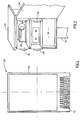
- a device 18 for photographically monitoring the intersection 10 is arranged in a housing 20 which is arranged on a column 22 at a short distance from the intersection 10.
- the device 18 contains a control and evaluation unit 24, a photographic camera 26 controlled by the control and evaluation unit and a flash unit 28.
- the control and evaluation unit 24 receives a sensor signal from the sensor 16 via a line 30 and a blocking phase signal from the traffic light 12 via a line 32 when the traffic light switches to the blocking phase.
- the camera 26, the flash unit and the control and evaluation unit are mounted in a housing-like insert 34.
- the insert 34 can be pulled out and reinserted from the housing 20 by means of two handles 36.
- the rear wall 38 of the housing 20 can be opened like a door. It is therefore possible, with such an insert 34, to equip a plurality of stationary housings optionally, that is to say as required or at irregular intervals.
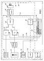
- the device is shown in a block diagram in FIG.
- the traffic light is again designated with 12 and the sensor installed in the road surface is designated with 16.
- the traffic light 12 delivers a signal during the blocking phase. This is represented by block 41.
- the signals from the sensor 16 and from the traffic light 12 can be adjusted Timers 42 and 44 are delayed by times T1 and T2. This allows differences between the different locations with regard to the position of the sensor 16 and the duration of the yellow phase, permitted tolerances or the like. be taken into account.
- the delayed signals act on a signal evaluation circuit 46, which practically corresponds to an AND gate. Subtleties of the circuit are omitted for simplicity of illustration.
- the signal evaluation circuit 46 controls a camera trigger 48.
- the camera trigger receives a trigger signal if a sensor signal is generated by the sensor 16 during the blocking phase.
- the camera 26 is triggered by the camera trigger 48.
- a picture is then taken which shows the intersection with the traffic light which is in the blocking phase and the vehicle 40 entering the intersection. Furthermore, displays of a location indicator 50, a clock 52 and a date indicator 54 are reflected in the recording.
- a time control 56 which is clocked by the clock 52, can prevent the triggering of the camera 26 at certain time intervals from t 1 to t 2. This is symbolized by a switch 58 between the signal evaluation circuit 46 and the camera trigger 48. The switch 58 is opened by the time controller 56 during these time intervals.
- the time intervals during which no pictures are to be taken depend on the location. They can be caused, for example, by the fact that the sun shines into the lens of the camera 26 during this time, so that no usable pictures can be taken.
- the parameters T1 and T2 and the time interval t1 to t2 and any other parameters depending on the location are stored in the form of a semiconductor data storage device 60 mounted in the housing 20 in the housing 20. These data storage means 60 transmit the parameters to the control and evaluation unit 24. This is indicated in FIG. 3 by lines 62, 64 and 66.
- the place of use indicator 50 information about the place of use is transmitted from the data storage means 60 to the place of use indicator 50.
- the device is thus automatically set to the correct parameters of the place of use when inserting the insert 34 into the housing 20 and the identifier of the place of use is also automatically entered into the place of use indicator 50.
- a setting by the user with each implementation is not required. Rather, the data need only be entered once into the data storage means 66 fixed to the housing and assigned to the housing 20.
- FIG. 4 shows a semiconductor data carrier that can be used as data storage means 60 in the form of a card-shaped integrated circuit 68 (memory card) with a contact strip 70.
- Memory cards are known per se and are commercially available (“Elektronik” 19 (1986), 100-101) .
- the data storage means may be formed by a coded plug or socket which are attached to the housing 20 and which, when the insert is inserted, make contact with a complementary counterpart of the insert 34.
- 5 shows a device for traffic monitoring, in which the speed of vehicles is monitored by means of a Doppler radar.
- the device 72 is located to the side of a street 74.
- a vehicle to be monitored is designated by 76.
- the device 72 contains a radar antenna 78 which transmits a "radar lobe" 80.
- the "radar lobe” represents the emitted radiation energy per solid angle as a function of the angle.
- the device 72 contains a photographic camera 82 which detects a field of view 84.
- the signals from the radar antenna 78 are connected to a measuring and evaluation circuit 86.
- the measuring and evaluation circuit 86 provides a measured value for the speed of the monitored vehicle 76 when the vehicle 76 has passed through the radar lobe 80.
- the camera 82 is triggered. It is triggered at a point in time at which the vehicle 76 is essentially in the middle of the field of view 84 of the camera 82.
- the camera 82 and the measurement and evaluation circuit 86 sit together with display devices in an insert 88.
- the insert 88 is in turn removably arranged in a stationary housing 90.
- a semiconductor data memory 92 or a coded plug socket is located in the housing 90.
- the semiconductor data memory transmits to the measuring and evaluation circuit 86 parameters for the operation of the device at the specific place of use.
- the data storage device delivers the maximum speed to be monitored at the place of use.
- the structure and function of the device is shown purely schematically in a block diagram in FIG.
- an insert 88 are the camera 82, the measurement and evaluation circuit 86, a location indicator 94, a clock 96 and a date display 98 is arranged.
- the measuring and evaluation circuit 86 contains a signal processing circuit 100 which forms a measured value for the speed of the vehicle 76 from the radar signals. This measured value is displayed by a display device 102. It is also compared by a comparator 104 at a predetermined maximum speed. If the measured value is higher than the maximum speed, a trigger signal is sent to a trigger 106 and the camera 82 is triggered.
- the camera 82 takes a picture of the monitored vehicle 76, the speed display on the display device 102 and the location display, the time and the date.
- the place of use is transmitted to the place of use display 94 via data line 108 by the data storage means.
- the permissible maximum speed applicable at the place of use is specified to the comparator 104 via line 110.
- a single insert can also be used either for speed monitoring or for monitoring a traffic light-controlled intersection as described in connection with FIG.
- the functions differ only in the signal processing.
- the program for the speed monitoring is called up via line 112 from the data storage means.
Landscapes
- Physics & Mathematics (AREA)
- General Physics & Mathematics (AREA)
- Traffic Control Systems (AREA)
Applications Claiming Priority (2)
| Application Number | Priority Date | Filing Date | Title |
|---|---|---|---|
| DE19873727503 DE3727503A1 (de) | 1987-08-18 | 1987-08-18 | Stationaere vorrichtung zur verkehrsueberwachung |
| DE3727503 | 1987-08-18 |
Publications (3)
| Publication Number | Publication Date |
|---|---|
| EP0303847A2 true EP0303847A2 (fr) | 1989-02-22 |
| EP0303847A3 EP0303847A3 (en) | 1989-09-06 |
| EP0303847B1 EP0303847B1 (fr) | 1990-10-03 |
Family
ID=6333978
Family Applications (1)
| Application Number | Title | Priority Date | Filing Date |
|---|---|---|---|
| EP88111737A Expired - Lifetime EP0303847B1 (fr) | 1987-08-18 | 1988-07-21 | Dispositif stationnaire de surveillance du trafic |
Country Status (6)
| Country | Link |
|---|---|
| US (1) | US4887080A (fr) |
| EP (1) | EP0303847B1 (fr) |
| JP (1) | JPS6466799A (fr) |
| CA (1) | CA1326888C (fr) |
| DD (1) | DD272939A5 (fr) |
| DE (2) | DE3727503A1 (fr) |
Cited By (3)
| Publication number | Priority date | Publication date | Assignee | Title |
|---|---|---|---|---|
| EP0593979A1 (fr) * | 1992-10-20 | 1994-04-27 | Daimler-Benz Aerospace Aktiengesellschaft | Dispositif d'enregistrement d'images en mouvement pour une installation de surveillance de feu rouge |
| EP0670564A1 (fr) * | 1994-03-01 | 1995-09-06 | ROBOT FOTO UND ELECTRONIC GmbH | Dispositif de surveillance du trafic dans des dispositifs de signalisation lumineuse commutable pour le guidage de la circulation |
| EP2605038A3 (fr) * | 2011-12-14 | 2013-12-04 | JENOPTIK Robot GmbH | Procédé et dispositif destinés à la détection dýun objet dans un champ radar |
Families Citing this family (48)
| Publication number | Priority date | Publication date | Assignee | Title |
|---|---|---|---|---|
| DE3727562C2 (de) * | 1987-08-19 | 1993-12-09 | Robot Foto Electr Kg | Vorrichtung zur Verkehrsüberwachung |
| US5408330A (en) * | 1991-03-25 | 1995-04-18 | Crimtec Corporation | Video incident capture system |
| ES2038920B1 (es) * | 1991-11-15 | 1995-01-16 | Electronic Traffic Sa | Procedimiento automatico de registro de imagenes por camara de tv. para informaciones de trafico. |
| JP2847682B2 (ja) * | 1991-11-22 | 1999-01-20 | 松下電器産業株式会社 | 交通信号無視取締り装置 |
| US5515042A (en) * | 1993-08-23 | 1996-05-07 | Nelson; Lorry | Traffic enforcement device |
| US5382953A (en) * | 1994-04-14 | 1995-01-17 | Hauptli; Wayne L. | Device for detecting school bus stop arm violations |
| KR960003444A (ko) * | 1994-06-01 | 1996-01-26 | 제임스 디. 튜턴 | 차량 감시 시스템 |
| KR960001777A (ko) * | 1994-06-01 | 1996-01-25 | 제임스 디. 튜턴 | 차량 감시 시스템 도플러 신호의 주파수 영역처리방법 |
| JP3195177B2 (ja) * | 1994-11-18 | 2001-08-06 | 株式会社豊田中央研究所 | 移動体特定装置 |
| US5525996A (en) * | 1995-02-10 | 1996-06-11 | Applied Concepts, Inc. | Police traffic radar for calculating and simultaneously displaying fastest target speed |
| US5528245A (en) * | 1995-02-10 | 1996-06-18 | Applied Concepts, Inc. | Police traffic radar using double balanced mixer for even order harmonic suppression |
| US6111523A (en) | 1995-11-20 | 2000-08-29 | American Traffic Systems, Inc. | Method and apparatus for photographing traffic in an intersection |
| US5938717A (en) * | 1996-03-04 | 1999-08-17 | Laser Technology, Inc. | Speed detection and image capture system for moving vehicles |
| US5948038A (en) | 1996-07-31 | 1999-09-07 | American Traffic Systems, Inc. | Traffic violation processing system |
| EP1070310A4 (fr) * | 1996-10-28 | 2001-01-24 | John B Moetteli | Systeme de repression des infractions au code de la route comportant des unites factices |
| US6462775B1 (en) | 1996-11-21 | 2002-10-08 | Detection Dynamics, Inc. | Apparatus within a street lamp for remote surveillance having directional antenna |
| US5886738A (en) * | 1996-11-21 | 1999-03-23 | Detection Dynamics Inc. | Apparatus within a street lamp for remote surveillance |
| US5929787A (en) * | 1996-11-27 | 1999-07-27 | Mee; Gary L. | Vibration actuated traffic light control system |
| US6760061B1 (en) | 1997-04-14 | 2004-07-06 | Nestor Traffic Systems, Inc. | Traffic sensor |
| US6121898A (en) * | 1997-10-28 | 2000-09-19 | Moetteli; John B. | Traffic law enforcement system |
| AU755840B2 (en) * | 1998-11-23 | 2002-12-19 | Nestor, Inc. | Traffic light collision avoidance system |
| US6754663B1 (en) | 1998-11-23 | 2004-06-22 | Nestor, Inc. | Video-file based citation generation system for traffic light violations |
| DE19963604C1 (de) * | 1999-12-23 | 2001-12-06 | Siemens Ag | Eisenbahnsignaleinrichtung |
| US7465108B2 (en) * | 2000-02-10 | 2008-12-16 | Cam Guard Systems, Inc. | Temporary surveillance system |
| US20080100707A1 (en) * | 2000-02-10 | 2008-05-01 | Cam Guard Systems, Inc. | Temporary surveillance system |
| US6375370B1 (en) * | 2000-02-10 | 2002-04-23 | Cam Guard Systems, Inc. | Temporary surveillance system |
| US6709172B2 (en) * | 2000-02-10 | 2004-03-23 | Cam Watch Systems, Inc. | Temporary surveillance system |
| US6426704B1 (en) * | 2000-08-17 | 2002-07-30 | Power Signal Technologies, Inc. | Modular upgradable solid state light source for traffic control |
| US6323781B1 (en) * | 2000-08-22 | 2001-11-27 | Power Signal Technologies | Electronically steerable light output viewing angles for traffic signals |
| US6614358B1 (en) * | 2000-08-29 | 2003-09-02 | Power Signal Technologies, Inc. | Solid state light with controlled light output |
| EP1233385A1 (fr) * | 2001-02-14 | 2002-08-21 | Siemens Building Technologies AG | Système de surveillance |
| US6961079B2 (en) * | 2001-06-21 | 2005-11-01 | Kenneth Kaylor | Portable traffic surveillance system |
| US6744379B1 (en) | 2001-08-16 | 2004-06-01 | Applied Concepts, Inc. | System and method for displaying radar data |
| US6845215B1 (en) | 2002-01-09 | 2005-01-18 | James Greenwold | Body-carryable, digital storage medium, audio/video recording assembly |
| WO2004032090A1 (fr) * | 2002-10-07 | 2004-04-15 | Ferdinand Kofel | Colonne de radar de controle de la vitesse |
| US7382277B2 (en) | 2003-02-12 | 2008-06-03 | Edward D. Ioli Trust | System for tracking suspicious vehicular activity |
| US7986339B2 (en) * | 2003-06-12 | 2011-07-26 | Redflex Traffic Systems Pty Ltd | Automated traffic violation monitoring and reporting system with combined video and still-image data |
| US7821422B2 (en) * | 2003-08-18 | 2010-10-26 | Light Vision Systems, Inc. | Traffic light signal system using radar-based target detection and tracking |
| US7558695B2 (en) * | 2004-08-10 | 2009-07-07 | Speedinfo, Llc | Self-powered vehicle speed sensor |
| WO2006094318A1 (fr) * | 2005-03-03 | 2006-09-08 | Gebert Ruediger Heinz | Systeme et procede de verification d'une mesure de vitesse |
| US8446467B2 (en) * | 2006-05-05 | 2013-05-21 | Scott K. Tilton | Combined speed detection, video and timing apparatus |
| US7541943B2 (en) * | 2006-05-05 | 2009-06-02 | Eis Electronic Integrated Systems Inc. | Traffic sensor incorporating a video camera and method of operating same |
| DE202007008461U1 (de) | 2007-06-14 | 2008-08-14 | Robot Visual Systems Gmbh | Verkehrsüberwachungssystem |
| EP2470395A1 (fr) * | 2009-08-24 | 2012-07-04 | James E. Winner | Détection de l'utilisation de dispositifs de communication mobile dans un véhicule |
| US8953044B2 (en) * | 2011-10-05 | 2015-02-10 | Xerox Corporation | Multi-resolution video analysis and key feature preserving video reduction strategy for (real-time) vehicle tracking and speed enforcement systems |
| US9024804B2 (en) * | 2012-09-14 | 2015-05-05 | Delphi Technologies, Inc. | Partial covering radome for a radar unit |
| DE202013004440U1 (de) | 2013-05-14 | 2014-05-16 | Thales Deutschland Gmbh | Schutzgehäuse zur Aufnahme mindestens einer gekapselten Baugruppe und Baugruppe hierfür |
| CN110322683A (zh) * | 2019-06-25 | 2019-10-11 | 北京停简单信息技术有限公司 | 用于园区的违章信息处理方法及装置 |
Citations (3)
| Publication number | Priority date | Publication date | Assignee | Title |
|---|---|---|---|---|
| DE1078797B (de) | 1958-03-04 | 1960-03-31 | Agfa Ag Leverkusen Bayerwerk | Einrichtung zur fotografischen Verkehrsueberwachung |
| CH414210A (de) | 1962-10-23 | 1966-05-31 | Telefunken Patent | Verfahren zur Geschwindigkeitsbestimmung von Objekten mittels eines Doppler-Radargerätes und zur Identifizierung derselben |
| DE2365331A1 (de) | 1973-02-14 | 1974-08-22 | Robot Foto Electr Kg | Vorrichtung zur photographischen ueberwachung von ampelgesteuerten kreuzungen |
Family Cites Families (6)
| Publication number | Priority date | Publication date | Assignee | Title |
|---|---|---|---|---|
| DE1154963B (de) * | 1959-09-08 | 1963-09-26 | Agfa Ag | Einrichtung zur Verkehrsueberwachung |
| DE2356909A1 (de) * | 1973-11-14 | 1975-05-15 | Agfa Gevaert Ag | Vorrichtung zur fotografischen verkehrsueberwachung |
| NL7403761A (nl) * | 1974-03-20 | 1975-09-23 | Nederland Haarlem Fabriek Van | Registrerend telapparaat. |
| US4173010A (en) * | 1975-05-01 | 1979-10-30 | Hoffmann Anton R | Traffic sign and improved system for recording vehicle speed |
| US4258430A (en) * | 1978-02-08 | 1981-03-24 | Tyburski Robert M | Information collection and storage system with removable memory |
| DE3422764A1 (de) * | 1984-06-20 | 1986-01-02 | Reinhold 7996 Meckenbeuren Fischer | System zum aufzeichnen von bildern und zugeordneten daten |
-
1987
- 1987-08-18 DE DE19873727503 patent/DE3727503A1/de not_active Withdrawn
-
1988
- 1988-07-21 EP EP88111737A patent/EP0303847B1/fr not_active Expired - Lifetime
- 1988-07-21 DE DE8888111737T patent/DE3860746D1/de not_active Expired - Fee Related
- 1988-08-11 US US07/231,158 patent/US4887080A/en not_active Expired - Fee Related
- 1988-08-12 CA CA000574645A patent/CA1326888C/fr not_active Expired - Fee Related
- 1988-08-16 DD DD88318984A patent/DD272939A5/de not_active IP Right Cessation
- 1988-08-18 JP JP63203969A patent/JPS6466799A/ja active Pending
Patent Citations (3)
| Publication number | Priority date | Publication date | Assignee | Title |
|---|---|---|---|---|
| DE1078797B (de) | 1958-03-04 | 1960-03-31 | Agfa Ag Leverkusen Bayerwerk | Einrichtung zur fotografischen Verkehrsueberwachung |
| CH414210A (de) | 1962-10-23 | 1966-05-31 | Telefunken Patent | Verfahren zur Geschwindigkeitsbestimmung von Objekten mittels eines Doppler-Radargerätes und zur Identifizierung derselben |
| DE2365331A1 (de) | 1973-02-14 | 1974-08-22 | Robot Foto Electr Kg | Vorrichtung zur photographischen ueberwachung von ampelgesteuerten kreuzungen |
Non-Patent Citations (1)
| Title |
|---|
| ELEKTRONIK, vol. 19, 1986, pages 100 - 101 |
Cited By (3)
| Publication number | Priority date | Publication date | Assignee | Title |
|---|---|---|---|---|
| EP0593979A1 (fr) * | 1992-10-20 | 1994-04-27 | Daimler-Benz Aerospace Aktiengesellschaft | Dispositif d'enregistrement d'images en mouvement pour une installation de surveillance de feu rouge |
| EP0670564A1 (fr) * | 1994-03-01 | 1995-09-06 | ROBOT FOTO UND ELECTRONIC GmbH | Dispositif de surveillance du trafic dans des dispositifs de signalisation lumineuse commutable pour le guidage de la circulation |
| EP2605038A3 (fr) * | 2011-12-14 | 2013-12-04 | JENOPTIK Robot GmbH | Procédé et dispositif destinés à la détection dýun objet dans un champ radar |
Also Published As
| Publication number | Publication date |
|---|---|
| DD272939A5 (de) | 1989-10-25 |
| DE3860746D1 (de) | 1990-11-08 |
| CA1326888C (fr) | 1994-02-08 |
| DE3727503A1 (de) | 1989-03-02 |
| EP0303847B1 (fr) | 1990-10-03 |
| US4887080A (en) | 1989-12-12 |
| EP0303847A3 (en) | 1989-09-06 |
| JPS6466799A (en) | 1989-03-13 |
Similar Documents
| Publication | Publication Date | Title |
|---|---|---|
| EP0303847B1 (fr) | Dispositif stationnaire de surveillance du trafic | |
| EP0236387B1 (fr) | Dispositif de surveillance photographique de carrefours | |
| DE69419189T2 (de) | Elektronisches Mautgebührenempfangssystem | |
| DE3727562C2 (de) | Vorrichtung zur Verkehrsüberwachung | |
| DE3787896T2 (de) | Elektronisches parkometersystem. | |
| EP0188694B1 (fr) | Procédé et dispositif pour la registration photographique de véhicules | |
| DE3728401A1 (de) | Verkehrsueberwachungseinrichtung | |
| DE3830598C2 (fr) | ||
| DE1805903C3 (de) | Verfahren und Vorrichtung zur Kameraauslösung bei einer Doppler-Radar-Geschwindigkeitsmeßeinrichtung für Fahrzeuge | |
| DE2234446B1 (de) | Vorrichtung zur verkehrsueberwachung | |
| DE102013104411B3 (de) | Verfahren zum Erfassen und Dokumentieren der Geschwindigkeiten mehrerer Fahrzeuge in einem Bilddokument | |
| US3858223A (en) | Device for photographic monitoring of road intersections controlled by a traffic light | |
| DE60106138T2 (de) | Verkehrsüberwachungssystem zur rechtzeitigen Signalisierung von Behinderungen in einem Verkehrsnetz | |
| DE3248565A1 (de) | Zeitintervall-messeinrichtung | |
| DE19517536A1 (de) | Einrichtung zur Verkehrsüberwachung mit einer Videokamera | |
| DE102008030903B4 (de) | Enforcement-Verfahren und Enforcement-Einrichtung zur Kontrolle eines elektronischen Mautsystems | |
| DE2529275C3 (de) | Verfahren und Schaltungsanordnung zur Durchführung des Verfahrens zur Messung von Fahrzeuggeschwindigkeiten | |
| EP0593979A1 (fr) | Dispositif d'enregistrement d'images en mouvement pour une installation de surveillance de feu rouge | |
| DE3135144A1 (de) | Fahrtrouten-anzeigevorrichtung zur visuellen anzeige einer aktuellen fahrtroute eines fahrzeuges | |
| EP0676735A1 (fr) | Dispositif de surveillance du trafic | |
| DE3332835A1 (de) | Einrichtung zur blitzfotografie | |
| DE2257631A1 (de) | Messgeraet mit einer messeinrichtung und einer damit kuppelbaren missbrauchsicherung | |
| CH685520A5 (de) | Laufzeitmesser. | |
| DE2429332A1 (de) | Vorrichtung zur ermittlung von parkgebuehren | |
| DD217909A1 (de) | Schaltungsanordnung zur belichtungssteuerung |
Legal Events
| Date | Code | Title | Description |
|---|---|---|---|
| PUAI | Public reference made under article 153(3) epc to a published international application that has entered the european phase |
Free format text: ORIGINAL CODE: 0009012 |
|
| AK | Designated contracting states |
Kind code of ref document: A2 Designated state(s): CH DE FR GB LI NL |
|
| PUAL | Search report despatched |
Free format text: ORIGINAL CODE: 0009013 |
|
| AK | Designated contracting states |
Kind code of ref document: A3 Designated state(s): CH DE FR GB LI NL |
|
| 17P | Request for examination filed |
Effective date: 19891002 |
|
| 17Q | First examination report despatched |
Effective date: 19891205 |
|
| GRAA | (expected) grant |
Free format text: ORIGINAL CODE: 0009210 |
|
| AK | Designated contracting states |
Kind code of ref document: B1 Designated state(s): CH DE FR GB LI NL |
|
| REF | Corresponds to: |
Ref document number: 3860746 Country of ref document: DE Date of ref document: 19901108 |
|
| ET | Fr: translation filed | ||
| GBT | Gb: translation of ep patent filed (gb section 77(6)(a)/1977) | ||
| PLBE | No opposition filed within time limit |
Free format text: ORIGINAL CODE: 0009261 |
|
| STAA | Information on the status of an ep patent application or granted ep patent |
Free format text: STATUS: NO OPPOSITION FILED WITHIN TIME LIMIT |
|
| 26N | No opposition filed | ||
| PGFP | Annual fee paid to national office [announced via postgrant information from national office to epo] |
Ref country code: GB Payment date: 19971112 Year of fee payment: 10 |
|
| PGFP | Annual fee paid to national office [announced via postgrant information from national office to epo] |
Ref country code: FR Payment date: 19971121 Year of fee payment: 10 |
|
| PGFP | Annual fee paid to national office [announced via postgrant information from national office to epo] |
Ref country code: CH Payment date: 19971127 Year of fee payment: 10 |
|
| PGFP | Annual fee paid to national office [announced via postgrant information from national office to epo] |
Ref country code: NL Payment date: 19971130 Year of fee payment: 10 |
|
| PG25 | Lapsed in a contracting state [announced via postgrant information from national office to epo] |
Ref country code: GB Free format text: LAPSE BECAUSE OF NON-PAYMENT OF DUE FEES Effective date: 19980721 |
|
| PG25 | Lapsed in a contracting state [announced via postgrant information from national office to epo] |
Ref country code: LI Free format text: LAPSE BECAUSE OF NON-PAYMENT OF DUE FEES Effective date: 19980731 Ref country code: CH Free format text: LAPSE BECAUSE OF NON-PAYMENT OF DUE FEES Effective date: 19980731 |
|
| PGFP | Annual fee paid to national office [announced via postgrant information from national office to epo] |
Ref country code: DE Payment date: 19980922 Year of fee payment: 11 |
|
| PG25 | Lapsed in a contracting state [announced via postgrant information from national office to epo] |
Ref country code: NL Free format text: LAPSE BECAUSE OF NON-PAYMENT OF DUE FEES Effective date: 19990201 |
|
| GBPC | Gb: european patent ceased through non-payment of renewal fee |
Effective date: 19980721 |
|
| REG | Reference to a national code |
Ref country code: CH Ref legal event code: PL |
|
| PG25 | Lapsed in a contracting state [announced via postgrant information from national office to epo] |
Ref country code: FR Free format text: LAPSE BECAUSE OF NON-PAYMENT OF DUE FEES Effective date: 19990331 |
|
| NLV4 | Nl: lapsed or anulled due to non-payment of the annual fee |
Effective date: 19990201 |
|
| REG | Reference to a national code |
Ref country code: FR Ref legal event code: ST |
|
| PG25 | Lapsed in a contracting state [announced via postgrant information from national office to epo] |
Ref country code: DE Free format text: LAPSE BECAUSE OF NON-PAYMENT OF DUE FEES Effective date: 20000503 |