EP0304062A2 - Broyeur à agitateur comportant un tuyau d'alimentation pour corps broyants - Google Patents
Broyeur à agitateur comportant un tuyau d'alimentation pour corps broyants Download PDFInfo
- Publication number
- EP0304062A2 EP0304062A2 EP88113447A EP88113447A EP0304062A2 EP 0304062 A2 EP0304062 A2 EP 0304062A2 EP 88113447 A EP88113447 A EP 88113447A EP 88113447 A EP88113447 A EP 88113447A EP 0304062 A2 EP0304062 A2 EP 0304062A2
- Authority
- EP
- European Patent Office
- Prior art keywords
- grinding
- agitator
- cavity
- grinding media
- feed pipe
- Prior art date
- Legal status (The legal status is an assumption and is not a legal conclusion. Google has not performed a legal analysis and makes no representation as to the accuracy of the status listed.)
- Withdrawn
Links
Images

Classifications
-
- B—PERFORMING OPERATIONS; TRANSPORTING
- B02—CRUSHING, PULVERISING, OR DISINTEGRATING; PREPARATORY TREATMENT OF GRAIN FOR MILLING
- B02C—CRUSHING, PULVERISING, OR DISINTEGRATING IN GENERAL; MILLING GRAIN
- B02C17/00—Disintegrating by tumbling mills, i.e. mills having a container charged with the material to be disintegrated with or without special disintegrating members such as pebbles or balls
- B02C17/18—Details
- B02C17/20—Disintegrating members
- B02C17/205—Adding disintegrating members to the tumbling mill
-
- B—PERFORMING OPERATIONS; TRANSPORTING
- B02—CRUSHING, PULVERISING, OR DISINTEGRATING; PREPARATORY TREATMENT OF GRAIN FOR MILLING
- B02C—CRUSHING, PULVERISING, OR DISINTEGRATING IN GENERAL; MILLING GRAIN
- B02C17/00—Disintegrating by tumbling mills, i.e. mills having a container charged with the material to be disintegrated with or without special disintegrating members such as pebbles or balls
- B02C17/16—Mills in which a fixed container houses stirring means tumbling the charge
Definitions
- the invention relates to an agitator mill with a grinding container, which contains a rotatably driven agitator and around it an at least partially fillable grinding media and grinding media, and with a feed tube through which grinding media can be fed from the outside to a central area of the grinding vessel while the agitator is running.
- Grinding media in agitator mills are subject to wear, which can be so considerable, especially when grinding abrasive ground material such as ferrites, that the grinding media shrinkage must be compensated for continuously or at short intervals so that the optimal operation of the agitator mill can be maintained.
- shrinkage of grinding media that occurs during grinding of a grinding stock, when changing to another grinding stock, it is usually necessary to replace the entire grinding media filling with another one that differs from the grinding media filling used previously in terms of material composition and / or the size of the grinding media or also differs simply in that the new grinding media filling has been cleaned outside the agitator mill.
- a device is known from DE-A 2 242 174 which has a housing with a cylindrical bore opening into the grinding chamber, the diameter of which is slightly smaller than the diameter of the grinding media.
- the wall of the bore is elastic so that the grinding media can be pushed through the bore in succession, at least one grinding media sealing the bore tightly.
- a piston is arranged in a section of the bore facing away from the grinding chamber and can be moved back and forth by a crank mechanism. With each stroke in the direction of the grinding chamber, this piston exerts a force on the rearmost grinding element in the bore, which force is transmitted via several grinding elements lying one behind the other in the bore, so that the frontmost grinding element is pushed into the grinding chamber.
- a device for feeding grinding media which also makes it possible to reuse used grinding media, is known from EP-A 0095149.
- a screw which can be driven in rotation is arranged as a conveying member in a tubular connecting piece between a grinding container and a storage container. Even with this, however, only relatively small quantities of regrind per unit of time can be introduced into the grinding chamber, since the screw can only run slowly, so that it does not damage the grinding media and is not itself damaged by them.
- document WO 86/02286 discloses an agitator mill of the type described at the outset, in which the fact that the grinding media present in the grinding chamber is in contact with the inner wall of the grinding vessel by the centrifugal force is used to compensate for grinding body shrinkage , form rotating granular bed, wherein in the center of the grinding chamber a space essentially free of grinding media is created. In this space, grinding media in the required refill quantities can be metered in freely via a feed pipe. Rotational speeds of the agitator, which give rise to a space free of grinding media in the center of the agitator mill and all around a grinding media packing of increased density, are not always desirable; they also result in an uneven distribution of the grinding media, which is not always advantageous.
- the invention is therefore based on the object of equipping an agitator mill with a device which enables rapid feeding and uniform distribution of grinding media.
- a negative pressure which is dependent on the speed of rotation of the agitator can be generated in the cavity compared to the pressure prevailing in the grinding chamber.
- This negative pressure can be used to convey grinding media through the feed pipe into the cavity and from there into the grinding chamber.
- the pressure gradient between the cavity and the grinding chamber which is dependent on the speed of rotation of the agitator
- the pressure gradient between the cavity and the external environment of the grinding container, in which grinding media are kept ready in an open container, for example has an influence on the flow of the grinding media through the feed pipe into the cavity .
- This pressure drop can be influenced using the means customary in agitator mills for controlling the inflow and outflow of regrind.
- An agitator mill with an agitator shaft which has a cavity open at the end at a free end section and recesses arranged around it, is known from EP-A 0 146 852.
- a separating device is arranged inside the cavity, through which ground material, which has entered the cavity from the front of the grinding chamber, can flow out in the axial direction of the grinding container.
- the recesses arranged around the cavity in the shaft end only have the task of essentially allowing radial flow back into the grinding chamber of grinding bodies which in principle inadvertently flowed into the cavity on the front side together with the grinding stock. There is no possibility of feeding fresh grinding media from the outside. The same also applies to a further development of the agitator mill described above from EP-A 0 206 207.
- the cavity is preferably also open in the axial direction of the agitator towards the grinding chamber.
- this feature can be implemented in such a way that the cavity is formed at a free end section of the agitator. In principle, however, it is possible to arrange the cavity into which the feed pipe opens at any point on a tubular agitator shaft.
- the feed tube is enclosed by a sleeve which, like in the known agitator mill described last, is fastened to an end wall of the grinding container and also extends into the cavity.
- a separating device for separating grinding media and grinding material and contains a grinding material outlet.
- the suction generated during rotation of the agitator, with which grinding media can be conveyed into the cavity through the feed tube, can be increased according to the invention in that the cavity is formed in a paddle wheel which is attached to the agitator and rotates coaxially with it.
- the cavity can be formed in a section of the agitator which is provided with hollow, rod-shaped stirring elements, through which grinding media can flow from the cavity into the grinding chamber.
- hollow, rod-shaped stirring elements through which grinding media can flow from the cavity into the grinding chamber.
- the feed tube contains a piston-type gate valve which can be displaced at least approximately to the cavity in order to shut off the flow of grinding media.
- the slide not only controls the inflow of grinding media, but in its blocking position it prevents regrind from entering the feed pipe and becoming lodged there.
- a rinsing line opens, which starts from a region of the grinding chamber lying radially outside the feed pipe.
- water or another rinsing liquid used for cleaning the grinding container for example a solvent, can be removed from the grinding container and at the same time used for cleaning the storage container, the feed line and the grinding media, wherever they are located.
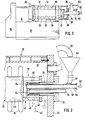
- the horizontal agitator mill shown in FIG. 1 has a box-shaped frame 10, on which an essentially cylindrical grinding container 12 and, axially next to it, a bearing housing 14 are fastened.
- the frame 10 contains a drive motor, not shown, and is connected to the bearing housing 14 by a gear housing 16, in which a gear, also not shown, with an adjustable transmission ratio is arranged.
- the grinding container 12 contains a circular cylindrical grinding chamber 18 in which an agitator 20 is arranged.
- the agitator 20 consists essentially of an agitator shaft 22 which is mounted in the bearing housing 14 and extends coaxially with the grinding container 12 through almost the entire grinding chamber 18, and a number of rod-shaped stirring elements 24 which are attached to the agitator mill 22 at equal axial intervals and protrude into spaces between counter-bars 26 attached to the grinding container 12.
- a grinding material inlet 28 At the left end of the grinding container 12 there is a grinding material inlet 28 through which a suspension or slurry of grinding material and liquid is continuously pumped into the grinding chamber 18 during operation.
- a regrind outlet 30 is arranged on the right end face of the grinding container 12, through which finished regrind is continuously pumped out.
- the regrind outlet has a sleeve on which a flange 34 is formed.
- the flange 34 is screwed to a cover 36 which forms the end face of the grinding container 12 facing away from the gear housing 16.
- the bridge 32 extends - coaxially with the agitator shaft 22 in the example shown in FIG. 2 - through the cover 36 and the adjacent area of the grinding chamber 18 to an end section 38 of the agitator shaft 22.
- the end section 38 is detachable from the main part of the Screwed agitator shaft 22 and has an open end or end cavity 40 in which a separator 42 is arranged.
- the separating device 42 is formed by a cylindrical sieve cartridge, which extends immediately after the bush 32 coaxially with the agitator shaft 22 over the greater part of the length of the cavity 40 and is closed off by a solid, plate-shaped end wall 44.
- slot-shaped, axially parallel outlet openings 46 are incorporated, each of which has an annular sector cross-section and extend over the greater part of the length of the cavity 40, so that the separating device 42 over its entire length from these outlet openings 46 is enclosed.
- the outlet openings 46 are separated from one another by axially parallel webs 48 of a cross-section which is also in the shape of an annular sector, so that the end section 38 as a whole resembles a cylindrical cage which is open on its end face.
- the grinding chamber 18 contains a mixture of grinding media 50 and grinding stock 52, which is activated during operation by rotating the agitator shaft 22 at a speed which is usual in agitator mills in the order of magnitude of, for example, 200 to 3000 revolutions per minute, depending on the nature of the grinding stock and Diameter of the agitator shaft and the grinding media.
- a vacuum is generated in the bridge 32 by a pump, not shown, the grinding media 50 and grinding stock 52 from the grinding chamber 18 into the cavity 40 can flow in through its open face.
- the finished regrind 52 passes through the separating device 42 into the bridge 32, while the grinding media 50 are retained and flow back into the grinding chamber 18 through the outlet openings 46. This backflow is promoted by the centrifugal forces resulting from the action of the webs 48 on the grinding media 50.
- the agitator mill shown corresponds to the prior art, as it results, for example, from EP-A 0 206 207.
- the rotation of the agitator shaft 22 creates a pressure drop between the cavity 40 and the grinding chamber 18 surrounding the agitator shaft 22, i.e. the pressure in the cavity 40 is lower than in the grinding chamber 18.
- This pressure drop and / or a negative pressure generated in the grinding chamber 18 by the aforementioned pump can be used to introduce grinding media 50 from the outside through a central feed pipe 54 into the cavity 40 and from there distribute in the grinding chamber 18.
- the feed pipe 54 extends parallel to the agitator shaft 22 through the bridge 32 at a small axial distance and is held in its flange 34 and in the end wall 44.
- a storage container 56 which contains grinding bodies 50 and has an outlet pipe 58 opening into the feed pipe 54.
- the connection between the outlet pipe 58 and the feed pipe 54 can be interrupted with a gate valve 60.
- the gate valve 60 is designed like a piston according to FIG. 2 and can be moved from the illustrated blocking position into an open position by means of a handle 62.
- the gate valve 60 In the locked position, the gate valve 60 extends at least approximately up to the protruding into the cavity 40, inner end of the feed pipe 54.
- the gate valve 60 clears the mouth of the outlet pipe 58, so that grinding media 50 trickle out of the reservoir 56 into the feed pipe 54 and can pass from there into the cavity 40. If grinding media 50 are to be fed at intervals, the gate valve 60 can be periodically pushed back and forth in the feed pipe 54; with each shift in the closing direction, it pushes a load of grinding media 50 in front of it into the cavity 40.
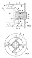
- the gate valve 60 carries near its end a seal 64, which is an O-ring seal according to FIGS. 2 and 3 . According to FIG. 2, this can be arranged in a conventional annular groove of the gate valve 60.
- the seal 64 is arranged in an annular groove of trapezoidal cross-section and adjustable width, which is formed between a rear shoulder 66 of the gate valve and a front shoulder 68 of a control slide 70.
- the control slide 70 is tubular and axially displaceable on the gate valve 60. Opening and closing movements are carried out jointly by the two slides 60 and 70.
- the control slide 70 In the closed position of the gate valve 60, the control slide 70 is moved somewhat further in the closing direction, as a result of which the annular groove between the shoulders 66 and 68 is narrowed and, as a result, the seal 64 is pressed radially outward against the inner wall of the feed tube 54.
- FIGS. 3 and 4 also differs from that shown in FIG. 2 in that a paddle wheel 72 is attached to the free end of the agitator shaft 22 is.
- This has a plurality of essentially radial blades 74, which are shown in two different variants and enclose the cavity 40. With the agitator 20 rotating, the blades 74 act like a rotary conveyor and fling grinding media 50 from the cavity 40 into the grinding chamber 18.
- the agitator 20 has, as in FIG. 2, an end section 38 screwed onto the end of the agitator shaft 22 with radial outlet openings 46.
- these are designed as bores to which a hollow, welded to the end section 38 is attached.
- rod-shaped stirring element 76 connects.
- the outlet openings 46 can be designed as threaded bores, into each of which a hollow rod-shaped stirring element 76 is screwed.
- the inflow of grinding media can be done 50 in the cavity 40 and further improve in the grinding chamber 18.
- a flushing line 78 is connected to a radially outer area of the grinding chamber 18, which leads into the storage container 56.
- a rinsing liquid can be supplied to the reservoir 56 from outside, which then flows through the feed pipe 54 into the cavity 40 and further into the grinding chamber 18 and can be drained off at a lower point of the grinding container 12 through a drain valve.
Landscapes
- Engineering & Computer Science (AREA)
- Food Science & Technology (AREA)
- Crushing And Grinding (AREA)
Applications Claiming Priority (2)
| Application Number | Priority Date | Filing Date | Title |
|---|---|---|---|
| DE3727863 | 1987-08-20 | ||
| DE19873727863 DE3727863C1 (de) | 1987-08-20 | 1987-08-20 | Ruehrwerksmuehle mit Zufuehrrohr fuer Mahlkoerper |
Publications (2)
| Publication Number | Publication Date |
|---|---|
| EP0304062A2 true EP0304062A2 (fr) | 1989-02-22 |
| EP0304062A3 EP0304062A3 (fr) | 1990-01-10 |
Family
ID=6334162
Family Applications (1)
| Application Number | Title | Priority Date | Filing Date |
|---|---|---|---|
| EP88113447A Withdrawn EP0304062A3 (fr) | 1987-08-20 | 1988-08-18 | Broyeur à agitateur comportant un tuyau d'alimentation pour corps broyants |
Country Status (2)
| Country | Link |
|---|---|
| EP (1) | EP0304062A3 (fr) |
| DE (1) | DE3727863C1 (fr) |
Cited By (3)
| Publication number | Priority date | Publication date | Assignee | Title |
|---|---|---|---|---|
| EP0468427A1 (fr) * | 1990-07-23 | 1992-01-29 | Kubota Corporation | Pulvérisateur |
| EP0700723A1 (fr) * | 1994-09-09 | 1996-03-13 | EVV-Vermögensverwaltungs-GmbH | Broyeur agitateur |
| CN103191804A (zh) * | 2013-04-19 | 2013-07-10 | 昆山聚贝机械设计有限公司 | 珠磨机组合型转子 |
Families Citing this family (5)
| Publication number | Priority date | Publication date | Assignee | Title |
|---|---|---|---|---|
| DE4002613A1 (de) * | 1990-01-30 | 1991-08-01 | Draiswerke Gmbh | Ruehrwerksmuehle |
| DE4029139A1 (de) * | 1990-09-13 | 1992-03-19 | Netzsch Erich Holding | Ruehrwerksmuehle |
| DE10057278C2 (de) * | 2000-11-17 | 2002-11-21 | Netzsch Erich Holding | Rührwerksmühle |
| DE102010052656B4 (de) | 2010-11-26 | 2025-08-21 | Netzsch-Feinmahltechnik Gmbh | Hydraulische mahlkugelzu- und abfuhr für rührwerkskugelmühlen |
| DE102015105103A1 (de) * | 2015-04-02 | 2016-10-06 | Netzsch-Feinmahltechnik Gmbh | Verschlusssystem für den Mahlbehälter einer Zerkleinerungseinrichtung und Mahlbehälter mit einem derartigen Verschlusssystem und Zerkleinerungseinrichtung mit einem Mahlbehälter |
Family Cites Families (6)
| Publication number | Priority date | Publication date | Assignee | Title |
|---|---|---|---|---|
| DE2110336A1 (de) * | 1971-03-04 | 1972-09-07 | Draiswerke Gmbh | Ruehrwerksmuehle |
| DE2242174A1 (de) * | 1972-08-26 | 1974-03-07 | Netzsch Maschinenfabrik | Verfahren und vorrichtung zum feinmahlen und dispergieren |
| EP0095149B1 (fr) * | 1982-05-25 | 1987-08-12 | Gebrüder Netzsch Maschinenfabrik GmbH & Co | Broyeur agitateur |
| DE3345680A1 (de) * | 1983-12-16 | 1985-06-20 | Gebrüder Netzsch, Maschinenfabrik GmbH & Co, 8672 Selb | Ruehrwerksmuehle |
| DE3437866A1 (de) * | 1984-10-16 | 1986-04-17 | Basf Farben + Fasern Ag, 2000 Hamburg | Dispergierverfahren und ruehrwerksmuehle zu seiner durchfuehrung |
| EP0206207B2 (fr) * | 1985-06-18 | 1994-03-02 | Erich Netzsch GmbH & Co. Holding KG | Broyeur agitateur |
-
1987
- 1987-08-20 DE DE19873727863 patent/DE3727863C1/de not_active Expired
-
1988
- 1988-08-18 EP EP88113447A patent/EP0304062A3/fr not_active Withdrawn
Cited By (3)
| Publication number | Priority date | Publication date | Assignee | Title |
|---|---|---|---|---|
| EP0468427A1 (fr) * | 1990-07-23 | 1992-01-29 | Kubota Corporation | Pulvérisateur |
| EP0700723A1 (fr) * | 1994-09-09 | 1996-03-13 | EVV-Vermögensverwaltungs-GmbH | Broyeur agitateur |
| CN103191804A (zh) * | 2013-04-19 | 2013-07-10 | 昆山聚贝机械设计有限公司 | 珠磨机组合型转子 |
Also Published As
| Publication number | Publication date |
|---|---|
| DE3727863C1 (de) | 1989-03-02 |
| EP0304062A3 (fr) | 1990-01-10 |
Similar Documents
| Publication | Publication Date | Title |
|---|---|---|
| DE3245825C2 (de) | Rührwerksmühle | |
| WO1985002559A1 (fr) | Moulin melangeur | |
| DE4128074C2 (de) | Rührwerkskugelmühle | |
| EP3311922B1 (fr) | Broyeur à billes à agitateur | |
| EP0376001B1 (fr) | Broyeur agitateur avec dispositif de séparation dans une cage rotative | |
| DE2709894A1 (de) | Filterzentrifuge | |
| CH620841A5 (fr) | ||
| DE69825261T2 (de) | Zentrifuge mit Mittelachse E | |
| EP0504836B1 (fr) | Broyeur agitateur | |
| EP0304062A2 (fr) | Broyeur à agitateur comportant un tuyau d'alimentation pour corps broyants | |
| DE69621249T2 (de) | Verfahren und vorrichtung zum reinigen des inneren einer zentrifugentrommel, sowie zentrifuge mit einer solchen vorrichtung | |
| DE3614721A1 (de) | Ruehrwerksmuehle | |
| DE3015631A1 (de) | Ruehrwerksmuehle | |
| EP0095149B1 (fr) | Broyeur agitateur | |
| EP1210987A2 (fr) | Dispositif pour obtenir des fractions grosses et fines à partir d' un mélange de sable | |
| EP0475015B1 (fr) | Procédé et appareil pour le broyage continu et la dispersion de solides dans des liquides | |
| EP0260604B1 (fr) | Broyeur à agitateur | |
| DE2240751A1 (de) | Ruehrwerksmuehle | |
| DE4010926A1 (de) | Ruehrwerksmuehle | |
| CH679461A5 (en) | Stirrer type grinding mill | |
| DE3511645C2 (de) | Straßenbearbeitungsmaschine | |
| CH674320A5 (en) | Agitator-type grinder - has rotor assembly in cylindrical grinding vessel which is detachable from inlet- and outlet part of grinder | |
| AT233925B (de) | Kugelmühle | |
| DE1184188B (de) | Ruehrwerksmuehle zur Herstellung von Feststoffdispersionen | |
| DE3141356A1 (de) | Zentrifuge mit volumetrisch dosiertem austrag der dichteren komponente |
Legal Events
| Date | Code | Title | Description |
|---|---|---|---|
| PUAI | Public reference made under article 153(3) epc to a published international application that has entered the european phase |
Free format text: ORIGINAL CODE: 0009012 |
|
| AK | Designated contracting states |
Kind code of ref document: A2 Designated state(s): BE CH DE FR GB IT LI |
|
| PUAL | Search report despatched |
Free format text: ORIGINAL CODE: 0009013 |
|
| AK | Designated contracting states |
Kind code of ref document: A3 Designated state(s): BE CH DE FR GB IT LI |
|
| 17P | Request for examination filed |
Effective date: 19891214 |
|
| 17Q | First examination report despatched |
Effective date: 19910411 |
|
| STAA | Information on the status of an ep patent application or granted ep patent |
Free format text: STATUS: THE APPLICATION IS DEEMED TO BE WITHDRAWN |
|
| 18D | Application deemed to be withdrawn |
Effective date: 19910822 |