EP0304199A2 - Injecteur de combustible - Google Patents
Injecteur de combustible Download PDFInfo
- Publication number
- EP0304199A2 EP0304199A2 EP88307197A EP88307197A EP0304199A2 EP 0304199 A2 EP0304199 A2 EP 0304199A2 EP 88307197 A EP88307197 A EP 88307197A EP 88307197 A EP88307197 A EP 88307197A EP 0304199 A2 EP0304199 A2 EP 0304199A2
- Authority
- EP
- European Patent Office
- Prior art keywords
- bore
- spring
- nozzle
- valve member
- transducer
- Prior art date
- Legal status (The legal status is an assumption and is not a legal conclusion. Google has not performed a legal analysis and makes no representation as to the accuracy of the status listed.)
- Granted
Links
Images

Classifications
-
- F—MECHANICAL ENGINEERING; LIGHTING; HEATING; WEAPONS; BLASTING
- F02—COMBUSTION ENGINES; HOT-GAS OR COMBUSTION-PRODUCT ENGINE PLANTS
- F02M—SUPPLYING COMBUSTION ENGINES IN GENERAL WITH COMBUSTIBLE MIXTURES OR CONSTITUENTS THEREOF
- F02M65/00—Testing fuel-injection apparatus, e.g. testing injection timing ; Cleaning of fuel-injection apparatus
- F02M65/005—Measuring or detecting injection-valve lift, e.g. to determine injection timing
-
- Y—GENERAL TAGGING OF NEW TECHNOLOGICAL DEVELOPMENTS; GENERAL TAGGING OF CROSS-SECTIONAL TECHNOLOGIES SPANNING OVER SEVERAL SECTIONS OF THE IPC; TECHNICAL SUBJECTS COVERED BY FORMER USPC CROSS-REFERENCE ART COLLECTIONS [XRACs] AND DIGESTS
- Y10—TECHNICAL SUBJECTS COVERED BY FORMER USPC
- Y10T—TECHNICAL SUBJECTS COVERED BY FORMER US CLASSIFICATION
- Y10T137/00—Fluid handling
- Y10T137/8158—With indicator, register, recorder, alarm or inspection means
Definitions
- This invention relates to a fuel injection nozzle for supplying fuel to a compression ignition engine, the nozzle being of the kind comprising a valve member which is biased by means of a spring to a closed position and which is moved to an open position against the force exerted by the spring, to allow fuel flow to the associated engine, by the pressure of fuel supplied to an inlet and the nozzle being adapted to carry means for providing an electrical signal indicative of the lifting of the valve member from the seating.
- a piezo-electric or piezo-resistive element as the means for generating the electrical signal and to mount the element intermediate one end of the spring and a reaction surface formed on the nozzle holder or on a part secured thereto, the other end of the spring being operatively connected to the valve member. All the force which is transmitted by the spring is applied to the element and because of the fragile nature of the element, great care has to be taken to ensure that the element is evenly stressed in use. In addition, great care has to be taken to ensure that the element is not unevenly stressed during the assembly and adjustment of the nozzle.
- the signal provided by the element provides an indication of the lifting of the valve member from the seating and this signal may be utilized in an electronic control system for the fuel system of the engine, and/or for testing purposes to ensure that delivery of fuel takes place at the required time.
- strain gauge elements mount on a support for the end of the spring remote from the valve member. In both cases the elements are located in the spring chamber of the nozzle in which in the use of the nozzle there is liquid fuel. In the case of the piezo-electric element it is essential to protect the element from the fuel and therefore special sealing arrangements are required. It is less essential to protect certain types of strain gauge elements for example wound elements but in each case it is necessary to pass the electrical connections through the wall of the chamber. Whatever method is employed it is necessary to form an adequate seal against fuel leakage. The provision of effective sealing arrangements adds substantially to the cost of such a nozzle over a conventional nozzle.
- the object of the present invention is to provide an injection nozzle of the kind specified in a simple and convenient form.
- the body of the nozzle defines a support surface for the end of the spring remote from the valve member, and there is formed in the body a blind bore which is open to the exterior of the body, said blind bore in use receiving a transducer element, and the bore being located in the vicinity of said surface whereby the transducer element when inserted in said bore, will provide an electrical signal indicative of changes in the stress in the spring as when the valve member is lifted from its seating.
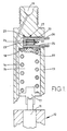
- a nozzle body or holder 13 has secured to it a nozzle unit 12 in which is mounted a valve member 11 which is urged to the closed position in which it engages with a seating by means of a prestressed coiled compression spring 14 located within a chamber 15 in the holder, the spring bearing against an abutment 17 carried on the valve member.
- the valve member in known manner, is lifted from the seating by fuel under pressure supplied through an inlet 16, the fuel flowing through a passage in the holder to a further passage in the nozzle body. When the valve member is lifted from the seating fuel can flow from the inlet to an outlet formed in the nozzle unit.
- the chamber 15 has an end wall 18 which defines a support surface against which there is located a spring abutment 19 which engages the end of the spring remote from the valve member. Moreover, extending into the holder is a blind bore 20. The axis of the bore is at right angles to the longitudinal axis of the body of the holder and the bore is drilled so that a thin section of wall remains between the bore and the chamber 15. The bore is therefore isolated from the chamber so that fuel within the chamber cannot leak into the bore.
- the bore 20 in use is arranged to receive a transducer which is generally indicated at 21 conveniently of the piezo-electric type having an outer metal sheath 22 and a central conductor 23, the two being held in spaced relationship by means of a filling 24 formed from polarized piezo-electric ceramic material.
- a transducer which is generally indicated at 21 conveniently of the piezo-electric type having an outer metal sheath 22 and a central conductor 23, the two being held in spaced relationship by means of a filling 24 formed from polarized piezo-electric ceramic material.
- the sheath can be a push fit into the bore so long as the slight distortion of the wall of the bore which occurs when the stress in the spring is raised is transmitted to the sheath.
- the spring abutment as shown in the drawing is relieved over its outer portion so that the loading is concentrated in the zone of the bore in which the transducer element is located.
- transducer element 21 it is convenient to mount the transducer element 21 in a metallic tubular member 25, the outer wall 26 of which is provided with a rib 27 which is a close fit in the bore and which is positioned in use in alignment with the unrelieved portion of the abutment 19. Moreover the inner end of the member 25 is closed and the inner surface at the outer end of the member is threaded to receive an electrical connector which includes a part for connection to the conductor 23.
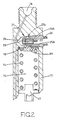
- the bore 20A has an inner tapered portion and the rib 27A on the tubular member 25A is shaped in like manner.
- the tubular member is provided with a screw thread for engagement with a complementary thread formed at the outer end of the bore.
- the bore 20B is formed in a cap nut 28 which is adjustably mounted in the holder 13B.
- the cap nut defines a support surface 18A for the spring abutment 19. Adjustment of the cap nut within the holder determines the force exerted by the spring 14.
- the element is mounted in the same manner as the example of Figure 1 but if desired the alternative form of arrangement of Figure 2 can be used. If instead of a piezo-electric element a piezo-resistive or strain gauge element is used, the signal provided by the element can be used to provide an indication of the spring force applied to the valve member and hence the nozzle opening pressure. It can therefore be used when adjusting the nozzle. It will still provide a signal indicative of the lift of the valve member when the nozzle is fitted to an engine.
- a lock nut 29 is provided to secure the cap nut in position once adjustment has been effected and a resilient seal 30 is provided to establish a fuel tight seal.
- an electrical signal which can provide an indication of when the valve member of the nozzle is lifted from its seating.
- the signal can be used in an electronic control system which controls the pump which supplies fuel to the nozzle and/or it can be used when timing the pump relative to the associated engine to ensure that fuel delivery occurs at the correct engine position.
Landscapes
- Engineering & Computer Science (AREA)
- Chemical & Material Sciences (AREA)
- Combustion & Propulsion (AREA)
- Mechanical Engineering (AREA)
- General Engineering & Computer Science (AREA)
- Fuel-Injection Apparatus (AREA)
Applications Claiming Priority (2)
| Application Number | Priority Date | Filing Date | Title |
|---|---|---|---|
| GB878719372A GB8719372D0 (en) | 1987-08-15 | 1987-08-15 | Fuel injection nozzle |
| GB8719372 | 1987-08-15 |
Publications (3)
| Publication Number | Publication Date |
|---|---|
| EP0304199A2 true EP0304199A2 (fr) | 1989-02-22 |
| EP0304199A3 EP0304199A3 (en) | 1990-02-21 |
| EP0304199B1 EP0304199B1 (fr) | 1992-01-02 |
Family
ID=10622368
Family Applications (1)
| Application Number | Title | Priority Date | Filing Date |
|---|---|---|---|
| EP88307197A Expired - Lifetime EP0304199B1 (fr) | 1987-08-15 | 1988-08-03 | Injecteur de combustible |
Country Status (6)
| Country | Link |
|---|---|
| US (1) | US4893750A (fr) |
| EP (1) | EP0304199B1 (fr) |
| JP (1) | JPH01100367A (fr) |
| DE (1) | DE3867378D1 (fr) |
| ES (1) | ES2028286T3 (fr) |
| GB (1) | GB8719372D0 (fr) |
Cited By (3)
| Publication number | Priority date | Publication date | Assignee | Title |
|---|---|---|---|---|
| WO1999032783A1 (fr) * | 1997-12-22 | 1999-07-01 | Stanadyne Automotive Corp. | Controle de la duree pour les injecteurs a rail commun |
| EP3026254A1 (fr) * | 2014-11-25 | 2016-06-01 | Robert Bosch Gmbh | Injecteur avec un capteur pour mesurer un cours de pression |
| EP3076005A1 (fr) * | 2015-04-02 | 2016-10-05 | Robert Bosch Gmbh | Injecteur de carburant et procédé de fabrication d'un injecteur de carburant |
Families Citing this family (14)
| Publication number | Priority date | Publication date | Assignee | Title |
|---|---|---|---|---|
| JP2686811B2 (ja) * | 1989-03-27 | 1997-12-08 | 株式会社ゼクセル | 燃料の噴射状態検知方法 |
| USH1962H1 (en) * | 1996-09-09 | 2001-06-05 | The United States Of America As Represented By The Secretary Of The Navy | Fast acting double puff valve |
| US20030129486A1 (en) * | 1999-08-11 | 2003-07-10 | Werner Bohnstedt | Battery separator provided with a plurality of studs and vertical ribs |
| US6836056B2 (en) | 2000-02-04 | 2004-12-28 | Viking Technologies, L.C. | Linear motor having piezo actuators |
| US6437226B2 (en) | 2000-03-07 | 2002-08-20 | Viking Technologies, Inc. | Method and system for automatically tuning a stringed instrument |
| US6548938B2 (en) * | 2000-04-18 | 2003-04-15 | Viking Technologies, L.C. | Apparatus having a pair of opposing surfaces driven by a piezoelectric actuator |
| US6717332B2 (en) | 2000-04-18 | 2004-04-06 | Viking Technologies, L.C. | Apparatus having a support structure and actuator |
| US6759790B1 (en) | 2001-01-29 | 2004-07-06 | Viking Technologies, L.C. | Apparatus for moving folded-back arms having a pair of opposing surfaces in response to an electrical activation |
| US6879087B2 (en) * | 2002-02-06 | 2005-04-12 | Viking Technologies, L.C. | Apparatus for moving a pair of opposing surfaces in response to an electrical activation |
| US6588262B2 (en) | 2001-02-14 | 2003-07-08 | Cummins Inc. | Motion sensor for high pressure fluid delivery device |
| WO2004001871A2 (fr) * | 2002-06-21 | 2003-12-31 | Viking Technologies, L.C. | Moteur piezo-electrique monobloc |
| CA2521307C (fr) | 2003-04-04 | 2014-07-15 | Viking Technologies, L.C. | Appareil et processus d'optimisation du travail a partir d'un dispositif de commande materiel intelligent |
| US9428164B2 (en) | 2013-02-28 | 2016-08-30 | Bendix Commercial Vehicle Systems Llc | Valve assembly |
| CN110863916B (zh) * | 2018-08-28 | 2024-04-16 | 罗伯特·博世有限公司 | 用于监测机械燃料喷射器的状态的方法 |
Family Cites Families (5)
| Publication number | Priority date | Publication date | Assignee | Title |
|---|---|---|---|---|
| DE2143676A1 (de) * | 1971-09-01 | 1973-03-08 | Volkswagenwerk Ag | Diagnoseeinrichtung fuer mit einer kraftstoff-einspritzvorrichtung ausgeruestete brennkraftmaschinen |
| DE3029721A1 (de) * | 1980-08-06 | 1982-03-04 | Robert Bosch Gmbh, 7000 Stuttgart | Kraftstoff-einspritzventil fuer brennkraftmaschinen |
| US4429570A (en) * | 1981-09-25 | 1984-02-07 | Essex Group, Inc. | Injection timing transducer |
| GB8402469D0 (en) * | 1984-01-31 | 1984-03-07 | Lucas Ind Plc | Fuel injection nozzles |
| US4662564A (en) * | 1984-05-15 | 1987-05-05 | Diesel Kiki Co., Ltd. | Fuel injection nozzle with timing sensor |
-
1987
- 1987-08-15 GB GB878719372A patent/GB8719372D0/en active Pending
-
1988
- 1988-08-03 ES ES198888307197T patent/ES2028286T3/es not_active Expired - Lifetime
- 1988-08-03 EP EP88307197A patent/EP0304199B1/fr not_active Expired - Lifetime
- 1988-08-03 DE DE8888307197T patent/DE3867378D1/de not_active Expired - Lifetime
- 1988-08-05 US US07/229,180 patent/US4893750A/en not_active Expired - Fee Related
- 1988-08-10 JP JP63199761A patent/JPH01100367A/ja active Pending
Cited By (3)
| Publication number | Priority date | Publication date | Assignee | Title |
|---|---|---|---|---|
| WO1999032783A1 (fr) * | 1997-12-22 | 1999-07-01 | Stanadyne Automotive Corp. | Controle de la duree pour les injecteurs a rail commun |
| EP3026254A1 (fr) * | 2014-11-25 | 2016-06-01 | Robert Bosch Gmbh | Injecteur avec un capteur pour mesurer un cours de pression |
| EP3076005A1 (fr) * | 2015-04-02 | 2016-10-05 | Robert Bosch Gmbh | Injecteur de carburant et procédé de fabrication d'un injecteur de carburant |
Also Published As
| Publication number | Publication date |
|---|---|
| EP0304199A3 (en) | 1990-02-21 |
| GB8719372D0 (en) | 1987-09-23 |
| ES2028286T3 (es) | 1992-07-01 |
| EP0304199B1 (fr) | 1992-01-02 |
| JPH01100367A (ja) | 1989-04-18 |
| DE3867378D1 (de) | 1992-02-13 |
| US4893750A (en) | 1990-01-16 |
Similar Documents
| Publication | Publication Date | Title |
|---|---|---|
| US4893750A (en) | Fuel injection nozzle | |
| US6298731B1 (en) | Combination pressure sensor and regulator for direct injection engine fuel system | |
| KR100583388B1 (ko) | 내연기관 연료 분사기용 조절가능한 계량밸브 및 그 조절방법 | |
| EP1854993B1 (fr) | Soupape d'injection du carburant | |
| US6345606B1 (en) | Method for controlling fuel rail pressure using a piezoelectric actuated fuel injector | |
| US4826080A (en) | Fuel injection device for internal combustion engines | |
| US6224001B1 (en) | Fuel injector | |
| US6648248B2 (en) | Solenoid valve and fuel injector using same | |
| US6135091A (en) | Fuel injection system | |
| FR2736396A1 (fr) | Injecteur de carburant pour moteur a combustion interne | |
| EP0333096A2 (fr) | Porte soupape pour un injecteur de carburant du type accumulateur | |
| EP0483770B1 (fr) | Système d'étanchéité haute pression pour la soupape de commande d'un injecteur électromagnétique de combustible pour moteur à combustion interne | |
| JPS60119366A (ja) | 燃料噴射ポンプ用の圧力弁 | |
| US4662564A (en) | Fuel injection nozzle with timing sensor | |
| DE102005035062A1 (de) | Vorrichtung zur Erfassung des Brennraumdrucks einer Brennkraftmaschine | |
| US20110006137A1 (en) | Sealed electric feedthrough | |
| US4461170A (en) | Fuel injection device for Diesel engines | |
| US20030116656A1 (en) | Fuel injection valve | |
| EP0338710B1 (fr) | Buse d'injection de combustible | |
| US4890498A (en) | Pressure sensor | |
| US20040084998A1 (en) | Control valve for liquids | |
| WO1992005363A1 (fr) | Gicleurs d'injection de carburant | |
| US5704552A (en) | Injector | |
| EP1136694A2 (fr) | Détecteur d'état pour injecteur de combustible | |
| EP3604789A1 (fr) | Vanne de réglage de pression pour système d'injection de carburant |
Legal Events
| Date | Code | Title | Description |
|---|---|---|---|
| PUAI | Public reference made under article 153(3) epc to a published international application that has entered the european phase |
Free format text: ORIGINAL CODE: 0009012 |
|
| AK | Designated contracting states |
Kind code of ref document: A2 Designated state(s): DE ES FR GB IT |
|
| PUAL | Search report despatched |
Free format text: ORIGINAL CODE: 0009013 |
|
| AK | Designated contracting states |
Kind code of ref document: A3 Designated state(s): DE ES FR GB IT |
|
| 17P | Request for examination filed |
Effective date: 19900723 |
|
| 17Q | First examination report despatched |
Effective date: 19910221 |
|
| GRAA | (expected) grant |
Free format text: ORIGINAL CODE: 0009210 |
|
| AK | Designated contracting states |
Kind code of ref document: B1 Designated state(s): DE ES FR GB IT |
|
| ITF | It: translation for a ep patent filed | ||
| REF | Corresponds to: |
Ref document number: 3867378 Country of ref document: DE Date of ref document: 19920213 |
|
| ET | Fr: translation filed | ||
| REG | Reference to a national code |
Ref country code: ES Ref legal event code: FG2A Ref document number: 2028286 Country of ref document: ES Kind code of ref document: T3 |
|
| PLBE | No opposition filed within time limit |
Free format text: ORIGINAL CODE: 0009261 |
|
| STAA | Information on the status of an ep patent application or granted ep patent |
Free format text: STATUS: NO OPPOSITION FILED WITHIN TIME LIMIT |
|
| 26N | No opposition filed | ||
| PGFP | Annual fee paid to national office [announced via postgrant information from national office to epo] |
Ref country code: GB Payment date: 19980727 Year of fee payment: 11 |
|
| PGFP | Annual fee paid to national office [announced via postgrant information from national office to epo] |
Ref country code: DE Payment date: 19980810 Year of fee payment: 11 |
|
| PGFP | Annual fee paid to national office [announced via postgrant information from national office to epo] |
Ref country code: FR Payment date: 19980814 Year of fee payment: 11 Ref country code: ES Payment date: 19980814 Year of fee payment: 11 |
|
| PG25 | Lapsed in a contracting state [announced via postgrant information from national office to epo] |
Ref country code: GB Free format text: LAPSE BECAUSE OF NON-PAYMENT OF DUE FEES Effective date: 19990803 |
|
| PG25 | Lapsed in a contracting state [announced via postgrant information from national office to epo] |
Ref country code: ES Free format text: LAPSE BECAUSE OF NON-PAYMENT OF DUE FEES Effective date: 19990804 |
|
| GBPC | Gb: european patent ceased through non-payment of renewal fee |
Effective date: 19990803 |
|
| PG25 | Lapsed in a contracting state [announced via postgrant information from national office to epo] |
Ref country code: FR Free format text: LAPSE BECAUSE OF NON-PAYMENT OF DUE FEES Effective date: 20000428 |
|
| PG25 | Lapsed in a contracting state [announced via postgrant information from national office to epo] |
Ref country code: DE Free format text: LAPSE BECAUSE OF NON-PAYMENT OF DUE FEES Effective date: 20000601 |
|
| REG | Reference to a national code |
Ref country code: FR Ref legal event code: ST |
|
| REG | Reference to a national code |
Ref country code: ES Ref legal event code: FD2A Effective date: 20000911 |
|
| PG25 | Lapsed in a contracting state [announced via postgrant information from national office to epo] |
Ref country code: IT Free format text: LAPSE BECAUSE OF NON-PAYMENT OF DUE FEES;WARNING: LAPSES OF ITALIAN PATENTS WITH EFFECTIVE DATE BEFORE 2007 MAY HAVE OCCURRED AT ANY TIME BEFORE 2007. THE CORRECT EFFECTIVE DATE MAY BE DIFFERENT FROM THE ONE RECORDED. Effective date: 20050803 |