EP0304334A2 - Transmission à commande manuelle pour véhicule - Google Patents
Transmission à commande manuelle pour véhicule Download PDFInfo
- Publication number
- EP0304334A2 EP0304334A2 EP88307729A EP88307729A EP0304334A2 EP 0304334 A2 EP0304334 A2 EP 0304334A2 EP 88307729 A EP88307729 A EP 88307729A EP 88307729 A EP88307729 A EP 88307729A EP 0304334 A2 EP0304334 A2 EP 0304334A2
- Authority
- EP
- European Patent Office
- Prior art keywords
- gears
- gear
- input
- countershaft
- drive
- Prior art date
- Legal status (The legal status is an assumption and is not a legal conclusion. Google has not performed a legal analysis and makes no representation as to the accuracy of the status listed.)
- Ceased
Links
Images


Classifications
-
- F—MECHANICAL ENGINEERING; LIGHTING; HEATING; WEAPONS; BLASTING
- F16—ENGINEERING ELEMENTS AND UNITS; GENERAL MEASURES FOR PRODUCING AND MAINTAINING EFFECTIVE FUNCTIONING OF MACHINES OR INSTALLATIONS; THERMAL INSULATION IN GENERAL
- F16H—GEARING
- F16H3/00—Toothed gearings for conveying rotary motion with variable gear ratio or for reversing rotary motion
- F16H3/02—Toothed gearings for conveying rotary motion with variable gear ratio or for reversing rotary motion without gears having orbital motion
- F16H3/08—Toothed gearings for conveying rotary motion with variable gear ratio or for reversing rotary motion without gears having orbital motion exclusively or essentially with continuously meshing gears, that can be disengaged from their shafts
- F16H3/087—Toothed gearings for conveying rotary motion with variable gear ratio or for reversing rotary motion without gears having orbital motion exclusively or essentially with continuously meshing gears, that can be disengaged from their shafts characterised by the disposition of the gears
- F16H3/093—Toothed gearings for conveying rotary motion with variable gear ratio or for reversing rotary motion without gears having orbital motion exclusively or essentially with continuously meshing gears, that can be disengaged from their shafts characterised by the disposition of the gears with two or more countershafts
- F16H3/097—Toothed gearings for conveying rotary motion with variable gear ratio or for reversing rotary motion without gears having orbital motion exclusively or essentially with continuously meshing gears, that can be disengaged from their shafts characterised by the disposition of the gears with two or more countershafts the input and output shafts being aligned on the same axis
-
- Y—GENERAL TAGGING OF NEW TECHNOLOGICAL DEVELOPMENTS; GENERAL TAGGING OF CROSS-SECTIONAL TECHNOLOGIES SPANNING OVER SEVERAL SECTIONS OF THE IPC; TECHNICAL SUBJECTS COVERED BY FORMER USPC CROSS-REFERENCE ART COLLECTIONS [XRACs] AND DIGESTS
- Y10—TECHNICAL SUBJECTS COVERED BY FORMER USPC
- Y10T—TECHNICAL SUBJECTS COVERED BY FORMER US CLASSIFICATION
- Y10T74/00—Machine element or mechanism
- Y10T74/19—Gearing
- Y10T74/19219—Interchangeably locked
- Y10T74/19233—Plurality of counter shafts
-
- Y—GENERAL TAGGING OF NEW TECHNOLOGICAL DEVELOPMENTS; GENERAL TAGGING OF CROSS-SECTIONAL TECHNOLOGIES SPANNING OVER SEVERAL SECTIONS OF THE IPC; TECHNICAL SUBJECTS COVERED BY FORMER USPC CROSS-REFERENCE ART COLLECTIONS [XRACs] AND DIGESTS
- Y10—TECHNICAL SUBJECTS COVERED BY FORMER USPC
- Y10T—TECHNICAL SUBJECTS COVERED BY FORMER US CLASSIFICATION
- Y10T74/00—Machine element or mechanism
- Y10T74/19—Gearing
- Y10T74/19219—Interchangeably locked
- Y10T74/19242—Combined gear and clutch
-
- Y—GENERAL TAGGING OF NEW TECHNOLOGICAL DEVELOPMENTS; GENERAL TAGGING OF CROSS-SECTIONAL TECHNOLOGIES SPANNING OVER SEVERAL SECTIONS OF THE IPC; TECHNICAL SUBJECTS COVERED BY FORMER USPC CROSS-REFERENCE ART COLLECTIONS [XRACs] AND DIGESTS
- Y10—TECHNICAL SUBJECTS COVERED BY FORMER USPC
- Y10T—TECHNICAL SUBJECTS COVERED BY FORMER US CLASSIFICATION
- Y10T74/00—Machine element or mechanism
- Y10T74/19—Gearing
- Y10T74/19219—Interchangeably locked
- Y10T74/19377—Slidable keys or clutches
- Y10T74/19386—Multiple clutch shafts
- Y10T74/19391—Progressive
-
- Y—GENERAL TAGGING OF NEW TECHNOLOGICAL DEVELOPMENTS; GENERAL TAGGING OF CROSS-SECTIONAL TECHNOLOGIES SPANNING OVER SEVERAL SECTIONS OF THE IPC; TECHNICAL SUBJECTS COVERED BY FORMER USPC CROSS-REFERENCE ART COLLECTIONS [XRACs] AND DIGESTS
- Y10—TECHNICAL SUBJECTS COVERED BY FORMER USPC
- Y10T—TECHNICAL SUBJECTS COVERED BY FORMER US CLASSIFICATION
- Y10T74/00—Machine element or mechanism
- Y10T74/19—Gearing
- Y10T74/19219—Interchangeably locked
- Y10T74/19377—Slidable keys or clutches
- Y10T74/19386—Multiple clutch shafts
- Y10T74/194—Selective
Definitions
- the present invention relates to a manual transmission for motor vehicles, and more particularly to a varialbe speed manual transmission of the type which includes four axes upon which the drive elements are mounted.
- U.S. Patent No. 4,458,551 issued on July 10, 1984 discloses a variable speed manual transmission which includes an input shaft having a drive pinion fixed thereon, an output shaft coaxial with the input shaft and having a first synchronizer coupling adapted to selectively connect the input shaft to the output shaft and first, second, third fourth and fifth pinions, a first intermediate shaft having first and second gears fixed thereon and located on opposite axial ends of the first synchronizer coupling, a second synchronizer coupling mounted thereon, and third and fourth gears selectively connectable to the first intermediate shaft by the second synchronizer coupling, and a second intermediate shaft having a fifth gear fixed thereon, a third synchronizer coupling mounted thereon, and sixth and seventh gears selectively connectable to the second intermediate shaft by the third synchronizer coupling.
- the third, fourth and fifth pinions are continuously engaged with the third, fourth and sixth gears, respectively, the first pionion is continuously engaged with the second gear, and the first and fifth gears are continuously engaged with the drive pionion.
- the axial length of the transmission may not be shortened due to coaxial arrangement of the input and output shafts, and the output shaft is located at the same height as the input shaft. For these reasons, it is difficult to manufacture the manual transmission in a compact construction, and it is also difficult to mount the manual transmission on a desired portion of a motor vehicle.
- a primary object of the present invention to provide an improved manual transmission the output shaft of which is located under the input shaft and in parallel therewith to shorten the axial length of the transmission and to facilitate the mounting of the transmission on a motor vehicle and the input shaft of which has a reverse drive gear fixed thereon to provide a reverse drive train in a simple construction without a reverse idler gear and an idler shaft for the same.
- a manual transmission which includes an input shaft having first and second drive gears fixed thereon respectively for low speed drive and high speed drive; an output shaft located under the input shaft and in parallel therewith and having at least a pair of axially spaced change-speed driven gears fixed thereon; a first countershaft arranged in parallel with the input and output shafts at one side thereof and having a first driven gear fixed thereon and continuously engaged with the first drive gear, a pair of axially spaced low speed drive gears rotatably mounted thereon and continuously engaged with the change-speed driven gears, and a first synchronizer coupling provided thereon to selectively connect the low speed drive gears to the first countershaft; and a second countershaft arranged in parallel with the input and output shafts at the other side thereof and having a second driven gear fixed thereon and continuously engaged with the second drive gear, a pair of axially spaced high speed drive gears rotatably mounted thereon and continuously engaged with the change-speed driven gears
- the input shaft has a reverse drive gear fixed thereon and the output shaft has a reverse driven gear axially slidably mounted thereon to be brought into meshing engagement with the reverse drive gear.
- the output shaft may be provided with a reverse driven gear rotatable thereon and continuously engaged with the reverse drive gear on the input shaft and provided thereon with a synchronizer coupling to selectively connect the reverse driven gear to the output shaft.
- the input and output shafts and the countershafts are rotatably mounted within a transmission housing
- the reverse drive gear is fixed on a rear end of the input shaft extending into an extension housing fastened to a rear end of the transmission housing
- the reverse driven gear is axially slidably mounted on a portion of the output shaft extending into the extension housing.
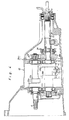
- a variable speed manual transmission TM1 has an input shaft 11, an output shaft 12 and two parallel countershafts 13, 14 rotatably mounted within a housing assembly 15 including a clutch housing part 15a, a transmission housing part 15b and an extension housing part 15c fastened together to be mounted as a unit on a motor vehicle of the front-engine rear-wheel drive type.
- the input shaft 11 is rotatably supported by a pair of axially spaced tapered roller bearings 16a and 16b respectively carried on upright rear end walls 15d and 15e of housing parts 15a and 15b.
- the input shaft 11 has a rear end extending into the extension housing part 15c.
- the output shaft 12 is located under the input shaft 11 and in parallel therewith and is rotatably supported by a pair of axially spaced tapered roller bearings 16c and 16d respectively carried on the upright rear end walls 15d and 15e.
- the output shaft 12 extends outwardly through the extension housing part 15c and is further supported by a ball bearing 16e carried on the rear end of housing part 15c.
- the countershafts 13 and 14 are arranged in parallel with the input and output shafts 11 and 12 at opposite sides thereof and are each located between the input and output shafts 11 and 12 in a vertical plane.
- the first countershaft 13 is rotatably supported by a pair of axially spaced tapered roller bearings 16f and 16g carried on the upright rear end walls 15d and 15e of housing parts 15a and 15d.
- the second countershaft 14 is rotatably supported by a pair of axially spaced tapered roller bearings 16h and 16i carried on the upright rear end walls 15d and 15e of housing parts 15a and 15b.
- the second countershaft 14 has a front end portion extending into the clutch housing part 15a.
- the input shaft 11 has a first drive gear 21a of small diameter for low speed drive and a second drive gear 22a of large diameter for high speed drive fixedly mounted thereon.
- the first drive gear 21a is continuously in meshing engagement with a first driven gear 21b of large diameter integrally provided on the first countershaft 13, while the second drive gear 22a is continuously in meshing engagement with a second driven gear 22b of small diameter integrally provided on the second countershaft 14.
- the first countershaft 13 has first and second forward drive gears 23a and 23b rotatably mounted thereon and a first synchronizer coupling 31 mounted thereon between the first and second forward drive gears 23a and 23b.
- the second countershaft 14 has third and fourth forward drive gears 23c and 23d rotatably mounted thereon and a second synchronizer coupling 32 mounted thereon between the third and fourth forward drive gears 23c and 23d.
- a clutch sleeve 32a of coupling 32 When a clutch sleeve 32a of coupling 32 is retained in a neutral position, the third and fourth forward drive gears 23c and 23d are conditioned to freely rotate on the second countershaft 14.
- the clutch sleeve 31a of coupling 32 is axially moved rearwards or forwards to selectively connect the third and fourth forward drive gears 23c and 23d to the second countershaft 14 for rotation therewith.
- the second countershaft 14 has a fifth forward drive gear 23e rotatably mounted on the front end thereof and located in the clutch housing part 15a and a third synchronizer coupling 33 provided thereon to selectively connect the fifth forward drive gear to the second countershaft 14.
- the output shaft 12 is integrally provided thereon with a first driven gear 24a of large diameter for the first and third speed ratios and a second driven gear 24d of small diameter for the second and fourth speed ratios.
- first driven gear 24a is continuously in meshing engagement with both the first and third forward drive gears 23a and 23c
- second driven gear 24d is continuously in meshing engagement with both the second and fourth forward drive gears 23b and 23d.
- the output shaft 12 has a third driven gear 24c for the fifth speed ratio fixed on a front end thereof extending into the clutch housing part 15a and continuously in meshing engagement with the fifth forward drive gear 23e.
- the input shaft 11 has a reverse drive gear 23f fixed on the rear end thereof
- the output shaft 12 has a spline portion 12a on which a reverse driven gear 24d is axially slidably mounted to be brought into meshing engagement with the reverse drive gear 23f.
- the reverse driven gear 24d is directly engaged with the reverse drive gear 23f to provide a reverse drive train.
- the input shaft 11 of manual transmission TM1 .s arranged to be drivingly connected to a crankshaft of a prime mover of the vehicle through a clutch mechanism (not shown), while the output shaft 12 is arranged to be drivingly connected to a rear propeller shaft (not shown).
- the power applied to input shaft 11 is transmitted to the first countershaft 13 through gears 21a and 21b and to the second countershaft 14 through gears 22a and 22b.
- the first synchronizer coupling 31 is moved rearwards to connect the first forward drive gear 32a to the first countershaft 13, the power is transmitted to the output shaft 12 through the first driven gear 24a as shown by a dash and dotted line a in Figs. 1 and 2.
- the first synchronizer coupling 31 is moved forwards to connect the second forward drive gear 32b to the first countershaft 13, the power is transmitted to the output shaft 12 through the second driven gear 24b as shown by a dash and dotted line b in Figs. 1 and 2.
- the output shaft 12 is located under the input shaft 11 and in parallel therewith and arranged also in parallel with the countershafts 13 and 14.
- the axial length of the manual transmission TM1 can be shortened to provide the manual transmission in a compact construction. Since the distance between the axially spaced bearings is shortened, thermal influence to each preload of the bearings can be reduced.
- the rear propeller shaft for connection to the output shaft 12 can be arranged in a lower position than the input shaft 11 to facilitate the mounting of the manual transmission on the vehicle.
- the manual transmission TM1 is further characterized in that the reverse drive gear 23f on input shaft 11 is directly engaged with the reverse driven gear 24d on output shaft 12 to establish the reverse drive train. With such an arrangement of the reverse drive and driven gears 23f and 24d, a conventional reverse idler gear and a reverse idler shaft for the same can be eliminated. Accordingly, a lubrication mechanism for the reverse idler gear and shaft is not needed. This is useful to reduce the number of component parts of the transmission and to reduce gear noises and loss of the power during forward drive of the vehicle.
- the manual transmission TM1 is also characterized in that the fifth drive gear 23e and third driven gear 24c are located in the clutch housing part 15a and that the reverse drive and driven gears 23f and 24d are located in the extension housing part 15c. With such an arrangement, dead spaces in housing parts 15a and 15c are utilized to contain the gears 23e, 24c, 23f and 24d therein. This is also useful to shorten the axial length of the transmission.
- Fig. 4 there is illustrated a modification of the manual transmission TM1 wherein the reverse driven gear 24d is replaced with a reverse driven gear 24e rotatably mounted on the output shaft 12 and continuously in meshing engagement with the reverse drive gear 23f on the input shaft 12.
- the output shaft 12 has a synchronizer coupling 34 provided thereon to selectively connect the reverse driven gear 24e to the output shaft 12.
- the reverse driven gear 24e When connected to the output shaft 12 by the synchronizer coupling 34, the reverse driven gear 24e cooperates with the reverse drive gear 23f to establish a reverse drive train.
- the other construction and component parts are the same as those in the manual transmission TM1 shown in Figs. 1-3.
Landscapes
- Engineering & Computer Science (AREA)
- General Engineering & Computer Science (AREA)
- Mechanical Engineering (AREA)
- Structure Of Transmissions (AREA)
Applications Claiming Priority (2)
| Application Number | Priority Date | Filing Date | Title |
|---|---|---|---|
| JP208822/87 | 1987-08-21 | ||
| JP62208822A JPS6455452A (en) | 1987-08-21 | 1987-08-21 | Manual transmission for vehicle |
Publications (2)
| Publication Number | Publication Date |
|---|---|
| EP0304334A2 true EP0304334A2 (fr) | 1989-02-22 |
| EP0304334A3 EP0304334A3 (fr) | 1990-01-24 |
Family
ID=16562687
Family Applications (1)
| Application Number | Title | Priority Date | Filing Date |
|---|---|---|---|
| EP88307729A Ceased EP0304334A3 (fr) | 1987-08-21 | 1988-08-19 | Transmission à commande manuelle pour véhicule |
Country Status (3)
| Country | Link |
|---|---|
| US (1) | US4869122A (fr) |
| EP (1) | EP0304334A3 (fr) |
| JP (1) | JPS6455452A (fr) |
Families Citing this family (4)
| Publication number | Priority date | Publication date | Assignee | Title |
|---|---|---|---|---|
| JP2686621B2 (ja) * | 1988-08-10 | 1997-12-08 | ヤンマーディーゼル株式会社 | 遊星歯車式前進二速減速逆転機 |
| JP2686622B2 (ja) * | 1988-08-10 | 1997-12-08 | ヤンマーディーゼル株式会社 | 遊星歯車式前進二速減速逆転機 |
| US9234567B2 (en) * | 2011-08-19 | 2016-01-12 | Jianwen Li | Gear change transmission having axially adjusting countershafts |
| CN107269775A (zh) * | 2017-07-27 | 2017-10-20 | 精进电动科技股份有限公司 | 一种横置车辆驱动总成 |
Family Cites Families (22)
| Publication number | Priority date | Publication date | Assignee | Title |
|---|---|---|---|---|
| DE12435C (de) * | L. A. enzinger in Worms a. Rh | Isobarometrischer Abfüll-Apparat für gashaltige Flüssigkeiten | ||
| US1825056A (en) * | 1921-12-06 | 1931-09-29 | Nat Acme Co | Mechanical movement |
| FR990127A (fr) * | 1944-03-03 | 1951-09-18 | Applic Ind Et Commerciales Int | Boîte de vitesse |
| US2511539A (en) * | 1947-10-09 | 1950-06-13 | Borg Warner | Five-speed transmission |
| US2694940A (en) * | 1949-09-30 | 1954-11-23 | Falk Corp | Multispeed transmission |
| US2825232A (en) * | 1955-01-19 | 1958-03-04 | Caterpillar Tractor Co | Gear type power transmission |
| GB769759A (en) * | 1955-03-21 | 1957-03-13 | Caterpillar Tractor Co | Gear type power transmission and control therefor |
| US3142195A (en) * | 1960-12-29 | 1964-07-28 | Clark Equipment Co | Transmission |
| US3301079A (en) * | 1964-09-15 | 1967-01-31 | Deere & Co | Vehicle transmission |
| US3318167A (en) * | 1964-12-23 | 1967-05-09 | Clark Equipment Co | Tri-shaft transmission |
| GB1094811A (en) * | 1965-01-06 | 1967-12-13 | A E C Ltd | Improvements in or relating to gear-boxes |
| US3498150A (en) * | 1968-07-15 | 1970-03-03 | Funk Mfg Co | Transmission |
| IT1072842B (it) * | 1977-04-20 | 1985-04-13 | Fiat Spa | Cambio a cinque marce per veicoli a motore |
| JPS53134156A (en) * | 1977-04-27 | 1978-11-22 | Kubota Ltd | Transmission of tractor |
| JPS54162330A (en) * | 1978-06-13 | 1979-12-22 | Nissan Motor Co Ltd | Industrial vehicle driving system |
| AU552791B2 (en) * | 1981-09-19 | 1986-06-19 | Automotive Products Plc | Transmission |
| JPS5894657A (ja) * | 1981-12-01 | 1983-06-04 | Toyota Motor Corp | 歯車式変速装置 |
| US4461188A (en) * | 1981-12-23 | 1984-07-24 | Ford Motor Company | Dual clutch multiple countershaft transmission |
| US4738150A (en) * | 1982-08-09 | 1988-04-19 | Borg-Warner Corporation | Compact manual transaxle transmission |
| JPH0637923B2 (ja) * | 1985-06-12 | 1994-05-18 | トヨタ自動車株式会社 | 車両用変速機 |
| SE454073B (sv) * | 1986-03-17 | 1988-03-28 | Volvo Ab | Motorfordonsvexellada |
| US4771647A (en) * | 1987-10-21 | 1988-09-20 | Caterpillar Inc. | Countershaft transmission |
-
1987
- 1987-08-21 JP JP62208822A patent/JPS6455452A/ja active Pending
-
1988
- 1988-08-19 US US07/234,152 patent/US4869122A/en not_active Expired - Fee Related
- 1988-08-19 EP EP88307729A patent/EP0304334A3/fr not_active Ceased
Also Published As
| Publication number | Publication date |
|---|---|
| EP0304334A3 (fr) | 1990-01-24 |
| US4869122A (en) | 1989-09-26 |
| JPS6455452A (en) | 1989-03-02 |
Similar Documents
| Publication | Publication Date | Title |
|---|---|---|
| US5335562A (en) | Multi-speed rear wheel drive transmission with reduced in-neutral gear rattle | |
| US4292860A (en) | Transfer device associated with power transmission | |
| US4458551A (en) | Manual transmission | |
| US5704247A (en) | Compact manual transaxle for motor vehicles | |
| US5881600A (en) | Transmission for motor vehicles | |
| US4738150A (en) | Compact manual transaxle transmission | |
| EP0210394B1 (fr) | Transmission pour véhicule à moteur | |
| US6832529B2 (en) | Automobile transmission | |
| US6067870A (en) | Manual transaxle | |
| CA1061603A (fr) | Transmission manuelle compacte pour moteur transversal | |
| US5697250A (en) | Compact manual transaxle | |
| EP0024454B1 (fr) | Dispositif de transmission pour véhicules automobiles | |
| EP0304275A2 (fr) | Boîte de vitesse commandée à la main | |
| GB2110323A (en) | Motor vehicle transmission | |
| US4869122A (en) | Manual transmission for motor vehicle | |
| EP0929761A1 (fr) | Boite-pont de type compact | |
| EP0305136A2 (fr) | Transmission à commande manuelle pour véhicule | |
| EP0206563A2 (fr) | Transmission à vitesses multiples avec un arbre intermédiaire | |
| JPH08159222A (ja) | 変速機 | |
| GB2113322A (en) | Multi-speed layshaft gearbox | |
| JPH0535289B2 (fr) | ||
| EP0096911A2 (fr) | Boîte de vitesses à étages | |
| EP0314382A2 (fr) | Boîte de vitesses à six rapports et à commande manuelle | |
| GB2162805A (en) | Four wheel drive transmission | |
| JP3078026B2 (ja) | 歯車式変速装置 |
Legal Events
| Date | Code | Title | Description |
|---|---|---|---|
| PUAI | Public reference made under article 153(3) epc to a published international application that has entered the european phase |
Free format text: ORIGINAL CODE: 0009012 |
|
| AK | Designated contracting states |
Kind code of ref document: A2 Designated state(s): DE FR GB |
|
| PUAL | Search report despatched |
Free format text: ORIGINAL CODE: 0009013 |
|
| AK | Designated contracting states |
Kind code of ref document: A3 Designated state(s): DE FR GB |
|
| 17P | Request for examination filed |
Effective date: 19900226 |
|
| 17Q | First examination report despatched |
Effective date: 19910705 |
|
| STAA | Information on the status of an ep patent application or granted ep patent |
Free format text: STATUS: THE APPLICATION HAS BEEN REFUSED |
|
| 18R | Application refused |
Effective date: 19921105 |