EP0304366B1 - Strukturteil für ein Fahrzeug, das an letzterem befestigt ist, um wenigstens teilweise als Trennwand zu dienen - Google Patents
Strukturteil für ein Fahrzeug, das an letzterem befestigt ist, um wenigstens teilweise als Trennwand zu dienen Download PDFInfo
- Publication number
- EP0304366B1 EP0304366B1 EP88401997A EP88401997A EP0304366B1 EP 0304366 B1 EP0304366 B1 EP 0304366B1 EP 88401997 A EP88401997 A EP 88401997A EP 88401997 A EP88401997 A EP 88401997A EP 0304366 B1 EP0304366 B1 EP 0304366B1
- Authority
- EP
- European Patent Office
- Prior art keywords
- component
- component according
- attached
- vehicle
- scuttle
- Prior art date
- Legal status (The legal status is an assumption and is not a legal conclusion. Google has not performed a legal analysis and makes no representation as to the accuracy of the status listed.)
- Expired - Lifetime
Links
- 238000000034 method Methods 0.000 claims description 10
- 239000007788 liquid Substances 0.000 claims description 5
- 238000009413 insulation Methods 0.000 claims description 3
- 238000005192 partition Methods 0.000 claims description 3
- 239000002131 composite material Substances 0.000 claims description 2
- 230000006835 compression Effects 0.000 claims description 2
- 238000007906 compression Methods 0.000 claims description 2
- 238000002347 injection Methods 0.000 claims description 2
- 239000007924 injection Substances 0.000 claims description 2
- 230000007246 mechanism Effects 0.000 claims 1
- 239000000470 constituent Substances 0.000 description 4
- 239000000463 material Substances 0.000 description 4
- 229910052751 metal Inorganic materials 0.000 description 4
- 239000012530 fluid Substances 0.000 description 3
- 238000004519 manufacturing process Methods 0.000 description 3
- 230000003749 cleanliness Effects 0.000 description 2
- 238000010276 construction Methods 0.000 description 2
- 238000012423 maintenance Methods 0.000 description 2
- 239000002184 metal Substances 0.000 description 2
- 229920000049 Carbon (fiber) Polymers 0.000 description 1
- 238000004026 adhesive bonding Methods 0.000 description 1
- 238000000429 assembly Methods 0.000 description 1
- 239000004917 carbon fiber Substances 0.000 description 1
- 230000001419 dependent effect Effects 0.000 description 1
- 230000000694 effects Effects 0.000 description 1
- 239000000945 filler Substances 0.000 description 1
- 239000003365 glass fiber Substances 0.000 description 1
- 210000000056 organ Anatomy 0.000 description 1
- 230000002787 reinforcement Effects 0.000 description 1
- 229920005989 resin Polymers 0.000 description 1
- 239000011347 resin Substances 0.000 description 1
- 230000000717 retained effect Effects 0.000 description 1
- 239000007787 solid Substances 0.000 description 1
- 239000000243 solution Substances 0.000 description 1
- 238000005406 washing Methods 0.000 description 1
- XLYOFNOQVPJJNP-UHFFFAOYSA-N water Substances O XLYOFNOQVPJJNP-UHFFFAOYSA-N 0.000 description 1
- 238000003466 welding Methods 0.000 description 1
Images
Classifications
-
- B—PERFORMING OPERATIONS; TRANSPORTING
- B62—LAND VEHICLES FOR TRAVELLING OTHERWISE THAN ON RAILS
- B62D—MOTOR VEHICLES; TRAILERS
- B62D25/00—Superstructure or monocoque structure sub-units; Parts or details thereof not otherwise provided for
- B62D25/08—Front or rear portions
-
- B—PERFORMING OPERATIONS; TRANSPORTING
- B62—LAND VEHICLES FOR TRAVELLING OTHERWISE THAN ON RAILS
- B62D—MOTOR VEHICLES; TRAILERS
- B62D25/00—Superstructure or monocoque structure sub-units; Parts or details thereof not otherwise provided for
- B62D25/08—Front or rear portions
- B62D25/081—Cowls
-
- B—PERFORMING OPERATIONS; TRANSPORTING
- B62—LAND VEHICLES FOR TRAVELLING OTHERWISE THAN ON RAILS
- B62D—MOTOR VEHICLES; TRAILERS
- B62D25/00—Superstructure or monocoque structure sub-units; Parts or details thereof not otherwise provided for
Definitions
- the present invention relates to motor vehicles and, more particularly, a structural part for the latter intended to be fixed, for example automatically.
- the invention relates more specifically to a structural part for a vehicle intended to be fixed to the latter to at least partially serve as an apron separating a front compartment from a passenger compartment.
- Contemporary vehicles in particular those known as “touring” vehicles, consist of a structure taking the place of the hull and / or chassis, obtained essentially from metal elements made of sheet metal, relatively thin, stamped and welded.
- Such a structure comprises, in particular, crosspieces associated with sidewalls which, inter alia, help to separate the front compartment, often engine, from the passenger compartment.
- These sleepers usually carry an apron and various bases and consoles to which various sub-assemblies are attached.
- bases or consoles and aprons are generally made from constituents stamped in metal sheets which are assembled to constitute mechanically welded entities.
- Such an apron is usually intended to separate this engine compartment from the passenger compartment so as to physically separate them from one another and, also, to ensure good sound insulation.
- this apron serves as a fire wall which contributes to delaying the spread of a fire which may have started in the vehicle.
- Such an apron is also often designed to allow passage to a steering column and the components of a crankset.
- it must also participate in the construction of the awning which is used to draw outside air for the renewal of that of the passenger compartment and also serves to support all or part of what is necessary to maintain cleanliness of the windshield, that is to say the wiper assembly with its motor and wheelhouse and the windshield washer with its pump and sprinklers.
- this technique uses separate sheets that must be shaped separately and then join together.
- the assembly poses problems as for the precision of the recording and the manner of bringing together in a final way the different sheets.
- the object of the invention is to manufacture a structural part for a vehicle intended to be fixed to the latter so as to serve at least partially as an apron separating a front compartment from a passenger compartment and which does not have all of these drawbacks.
- the subject of the invention is a structural part for a vehicle intended to be fixed to the latter so as to serve at least partially as an apron separating a front compartment from a passenger compartment.
- This part is of a type set out in the preamble to the main claim and whose features stand out in particular from the characterizing part thereof.
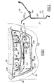
- a structure 10 of a vehicle has been schematically drawn in thin lines.
- This structure essentially comprises crosspieces 13, high and low, which bring together lateral flanks 14, right and left.
- This structure makes it possible to provide an anterior compartment 11, most often intended to receive a power unit and a passenger compartment 12 intended to accommodate the driver and his passengers, as can be seen in FIG. 2.
- the part 20 according to the invention is intended to be fixed to the structure 10 to at least partially serve as an apron separating the front compartment 11 from the passenger compartment 12.
- This piece is made of a one-piece element obtained in one piece.
- This part is, for example, made of composite materials such as resins with fillers or reinforcements, for example glass or carbon fibers, intended for modify the intrinsic mechanical properties for example.
- the materials are also chosen so as not only to obtain these mechanical characteristics but also so as to present acoustic characteristics such that this part contributes notably to obtain a good acoustic insulation so that the noises of the engine compartment are relatively correctly absorbed and, in all as far as possible, not transmitted to the passenger compartment to obtain good comfort for the occupants.
- Such a part can be made by an injection and / or compression technique for example.
- the choice of the technique used depends of course on the constituent materials retained, the tools available and, also, the properties to be obtained from the part thus manufactured.
- this part 20 comprises a wall 21, one of the sides of which forms a trough 22 which has a longitudinal axis 220, approximately parallel to this wall, and which is provided with a transverse partition 221 dividing it.
- an awning casing 30 and a tank 40 there is thus housed an awning casing 30 and a tank 40.
- the awning box 30 has an air intake 31 and provides a housing 32 and a room 33.
- the air intake 31 is intended to be connected to pipes, not shown, so that air taken from outside is directed to the passenger compartment 12 to renew its atmosphere or to cool it after crossing a fan and a heat exchanger, not shown, as is conventional.
- the housing 32 is intended to receive a wiper plate with its motor and all its wheelhouse; this plate is not shown because it is of any conventional type.
- Chamber 33 is intended to receive a windscreen washer with its pumps and possibly, its nozzles; this equipment is also not illustrated.
- the reservoir 40 forms a sealed enclosure which is intended to be closed by an attached cover, not drawn.
- This cover is, for example, permanently fixed by gluing, welding or other techniques ensuring in particular liquid tightness or else is removably mounted, for example by interlocking.
- Such a cover, not drawn is provided for example with a cap, which is also not drawn, for filling the reservoir.
- the canopy casing 30 is provided with a drain 34 in the area of the trough 22 which will be the lowest when the part 20 is definitively installed on the structure 10.
- This drain will be connected to a drainage pipe, not drawn, to discharge outside the water which could be received by the trough when the vehicle is traveling in rainy weather or during its washing, for example.
- part according to the invention makes it possible to group together all of the equipment which contributes to maintenance in a satisfactory state of cleanliness of the windshield.
- the part according to the invention makes it possible to provide a housing for a wiper plate, a room for a windscreen washer itself and also a reservoir for the liquid of the windscreen washer, which are all located nearby. from each other and very close. Such proximity makes it possible to group all or part of this equipment which is intended to be joined by pipes for the circulation of the liquid of the washer-fluid in particular.
- the circulation of fluids is therefore simplified, access to them is improved and the lengths of the pipes to be used are reduced. This brings great economic benefit to construction and maintenance.
- the housing 32 for a wiper plate and the chamber 33 for a windshield washer can be physically separated by solid or perforated partitions which can also contribute to the stiffening of the room according to the invention.
- the wall 21 of the part 20 according to the invention is pierced with orifices 211 and multiple passages 212 as well as flats 213 and anchor points 214. All this is intended to give passage to a steering column, components of the accelerator, brake and clutch pedals as well as harnesses of electric cables and other fluids, necessary for the control and operation of the vehicle; they are also intended for mounting these members. All of this is classic.
- part according to the invention is provided for example with tabs 215 and holes 216 intended for its attachment to the structure 10 using any suitable technique, for example by screwing or riveting.
- the part according to the invention makes it possible to significantly reduce the number of components involved compared to the conventional situation where such a part serving as a separating apron is made from numerous multiple constituents, most often stamped. and mechanically welded.
- the design of the part also allows, by its configuration, to use automatic assembly techniques using robots or automata.
- the part according to the invention also contributes to rationalizing the use of the volumes of the engine compartment and to grouping together a large number of organs which have functions which are relatively directly dependent on each other.
Landscapes
- Engineering & Computer Science (AREA)
- Chemical & Material Sciences (AREA)
- Combustion & Propulsion (AREA)
- Transportation (AREA)
- Mechanical Engineering (AREA)
- Body Structure For Vehicles (AREA)
- Vehicle Interior And Exterior Ornaments, Soundproofing, And Insulation (AREA)
Claims (9)
Applications Claiming Priority (2)
| Application Number | Priority Date | Filing Date | Title |
|---|---|---|---|
| FR8711645A FR2619544B1 (fr) | 1987-08-17 | 1987-08-17 | Piece de structure pour vehicule destinee a etre fixee a cette derniere pour servir au moins partiellement de tablier separateur |
| FR8711645 | 1987-08-17 |
Publications (2)
| Publication Number | Publication Date |
|---|---|
| EP0304366A1 EP0304366A1 (de) | 1989-02-22 |
| EP0304366B1 true EP0304366B1 (de) | 1991-01-09 |
Family
ID=9354247
Family Applications (1)
| Application Number | Title | Priority Date | Filing Date |
|---|---|---|---|
| EP88401997A Expired - Lifetime EP0304366B1 (de) | 1987-08-17 | 1988-07-29 | Strukturteil für ein Fahrzeug, das an letzterem befestigt ist, um wenigstens teilweise als Trennwand zu dienen |
Country Status (5)
| Country | Link |
|---|---|
| EP (1) | EP0304366B1 (de) |
| KR (1) | KR890003585A (de) |
| DE (1) | DE3861503D1 (de) |
| ES (1) | ES2019701B3 (de) |
| FR (1) | FR2619544B1 (de) |
Families Citing this family (6)
| Publication number | Priority date | Publication date | Assignee | Title |
|---|---|---|---|---|
| IT1273160B (it) * | 1994-04-27 | 1997-07-07 | Fiat Auto Spa | Struttura di autoveicolo e procedimento di assemblaggio di un autoveicolo avente una siffatta struttura |
| DE4424288A1 (de) * | 1994-07-09 | 1996-01-11 | Opel Adam Ag | Kraftfahrzeug |
| DE19920235B4 (de) * | 1999-05-03 | 2008-04-24 | Volkswagen Ag | Kraftfahrzeug mit einem Montagekasten an einer Stirnwand zwischen Motorraum und Fahrgastzelle |
| RU2223876C1 (ru) * | 2002-12-02 | 2004-02-20 | Открытое акционерное общество "АВТОВАЗ" | Устройство крепления панели приборов к кузову автомобиля |
| FR2875197A1 (fr) | 2004-09-14 | 2006-03-17 | Renault Sas | Vehicule automobile pourvu d'un dispositif de lave vitre |
| DE102008049763A1 (de) * | 2008-09-30 | 2010-04-01 | GM Global Technology Operations, Inc., Detroit | Karosserie für ein Kraftfahrzeug |
Family Cites Families (2)
| Publication number | Priority date | Publication date | Assignee | Title |
|---|---|---|---|---|
| IT1128474B (it) * | 1980-05-20 | 1986-05-28 | Fiat Auto Spa | Complesso di elementi con funzione di separazione tra l abitacolo ed il vano motore di un autoveicolo |
| DE3467543D1 (en) * | 1983-04-29 | 1987-12-23 | Opel Adam Ag | Pre-assembled modular unit for the driver's area of motor vehicles, particularly passenger cars, and method of installing such a pre-assembled modular unit |
-
1987
- 1987-08-17 FR FR8711645A patent/FR2619544B1/fr not_active Expired - Fee Related
-
1988
- 1988-07-29 EP EP88401997A patent/EP0304366B1/de not_active Expired - Lifetime
- 1988-07-29 DE DE8888401997T patent/DE3861503D1/de not_active Expired - Lifetime
- 1988-07-29 ES ES88401997T patent/ES2019701B3/es not_active Expired - Lifetime
- 1988-08-06 KR KR1019880010041A patent/KR890003585A/ko not_active Withdrawn
Also Published As
| Publication number | Publication date |
|---|---|
| FR2619544A1 (fr) | 1989-02-24 |
| KR890003585A (ko) | 1989-04-15 |
| DE3861503D1 (de) | 1991-02-14 |
| ES2019701B3 (es) | 1991-07-01 |
| FR2619544B1 (fr) | 1990-01-05 |
| EP0304366A1 (de) | 1989-02-22 |
Similar Documents
| Publication | Publication Date | Title |
|---|---|---|
| EP1063151B1 (de) | Cockpit | |
| FR2623776A1 (fr) | Poste de conduite preassemble pour habitacles de vehicules automobiles | |
| US20130087396A1 (en) | Utility Vehicle | |
| EP1032527A1 (de) | Vorderfront aus verstärkter umgossener metall- und kunststoffverbundwerkstoff fur kraftfahrzeuge | |
| FR2955529A1 (fr) | Element de recouvrement pour tableau de bord d'un vehicule automobile | |
| EP0304366B1 (de) | Strukturteil für ein Fahrzeug, das an letzterem befestigt ist, um wenigstens teilweise als Trennwand zu dienen | |
| FR3004156A1 (fr) | Plancher composite et vehicule automobile comportant un tel plancher | |
| FR2677943A1 (fr) | Facade anterieure perfectionnee pour vehicules automobiles. | |
| FR3078293A1 (fr) | Groupe motopropulseur de vehicule a machine electrique motrice suspendue a une traverse hybride a pieces de filtrage | |
| EP0311466B1 (de) | Struktur eines Kraftfahrzeuges mit selbsttragender Karosserie und sein Montageverfahren | |
| FR2747638A1 (fr) | Console centrale pour un vehicule automobile comportant un boitier de logement | |
| EP1308374A1 (de) | Verfahren zur Herstellen von zwei Armaturenbrettern durch Benutzung von zwei Luftschläuchen | |
| EP0494552B1 (de) | Aufbau eines Kraftfahrzeugbodens mit integriertem Kraftstofftank | |
| EP0438325B1 (de) | Trennwand für die Karosserie eines Kraftfahrzeuges | |
| JPS5911976A (ja) | 自動車のフロント骨格構造 | |
| FR2554408A1 (fr) | Caisson d'auvent de vehicule automobile et procede de montage de ce caisson | |
| WO2014136769A1 (ja) | 車両前部構造 | |
| US20060017272A1 (en) | Supporting member for a fender | |
| EP0845404B1 (de) | Feuerschutzwand für eine Kraftfahrzeugkarosserie mit einer Verstärkungsstütze | |
| FR3097822A1 (fr) | Structure de mise a la masse pour vehicule electrique | |
| FR2852569A1 (fr) | Module de face avant de vehicule automobile | |
| FR3139523A1 (fr) | Joint de protection à triple fonction pour une partie latérale d’une structure d’un véhicule | |
| EP0431986B1 (de) | Verbessertes Strukturteil für ein Fahrzeug und seine Verwendung bei einer automatischen Montage | |
| EP0955229A1 (de) | Kabine für ein Strassenfahrzeug | |
| FR3167079A1 (fr) | Tablier anti-vibrations pour un véhicule à pare-brise |
Legal Events
| Date | Code | Title | Description |
|---|---|---|---|
| PUAI | Public reference made under article 153(3) epc to a published international application that has entered the european phase |
Free format text: ORIGINAL CODE: 0009012 |
|
| AK | Designated contracting states |
Kind code of ref document: A1 Designated state(s): DE ES GB IT SE |
|
| 17P | Request for examination filed |
Effective date: 19881231 |
|
| 17Q | First examination report despatched |
Effective date: 19900220 |
|
| GRAA | (expected) grant |
Free format text: ORIGINAL CODE: 0009210 |
|
| AK | Designated contracting states |
Kind code of ref document: B1 Designated state(s): DE ES GB IT SE |
|
| GBT | Gb: translation of ep patent filed (gb section 77(6)(a)/1977) | ||
| ITF | It: translation for a ep patent filed | ||
| REF | Corresponds to: |
Ref document number: 3861503 Country of ref document: DE Date of ref document: 19910214 |
|
| PLBE | No opposition filed within time limit |
Free format text: ORIGINAL CODE: 0009261 |
|
| STAA | Information on the status of an ep patent application or granted ep patent |
Free format text: STATUS: NO OPPOSITION FILED WITHIN TIME LIMIT |
|
| 26N | No opposition filed | ||
| EAL | Se: european patent in force in sweden |
Ref document number: 88401997.7 |
|
| PGFP | Annual fee paid to national office [announced via postgrant information from national office to epo] |
Ref country code: SE Payment date: 19960716 Year of fee payment: 9 |
|
| PGFP | Annual fee paid to national office [announced via postgrant information from national office to epo] |
Ref country code: DE Payment date: 19970624 Year of fee payment: 10 |
|
| PGFP | Annual fee paid to national office [announced via postgrant information from national office to epo] |
Ref country code: GB Payment date: 19970722 Year of fee payment: 10 |
|
| PGFP | Annual fee paid to national office [announced via postgrant information from national office to epo] |
Ref country code: ES Payment date: 19970724 Year of fee payment: 10 |
|
| PG25 | Lapsed in a contracting state [announced via postgrant information from national office to epo] |
Ref country code: SE Effective date: 19970730 |
|
| EUG | Se: european patent has lapsed |
Ref document number: 88401997.7 |
|
| PG25 | Lapsed in a contracting state [announced via postgrant information from national office to epo] |
Ref country code: GB Free format text: LAPSE BECAUSE OF NON-PAYMENT OF DUE FEES Effective date: 19980729 |
|
| PG25 | Lapsed in a contracting state [announced via postgrant information from national office to epo] |
Ref country code: ES Free format text: LAPSE BECAUSE OF THE APPLICANT RENOUNCES Effective date: 19980730 |
|
| GBPC | Gb: european patent ceased through non-payment of renewal fee |
Effective date: 19980729 |
|
| PG25 | Lapsed in a contracting state [announced via postgrant information from national office to epo] |
Ref country code: DE Free format text: LAPSE BECAUSE OF NON-PAYMENT OF DUE FEES Effective date: 19990501 |
|
| REG | Reference to a national code |
Ref country code: ES Ref legal event code: FD2A Effective date: 20001102 |
|
| PG25 | Lapsed in a contracting state [announced via postgrant information from national office to epo] |
Ref country code: IT Free format text: LAPSE BECAUSE OF NON-PAYMENT OF DUE FEES;WARNING: LAPSES OF ITALIAN PATENTS WITH EFFECTIVE DATE BEFORE 2007 MAY HAVE OCCURRED AT ANY TIME BEFORE 2007. THE CORRECT EFFECTIVE DATE MAY BE DIFFERENT FROM THE ONE RECORDED. Effective date: 20050729 |